
gardner denver mud pump parts list free sample

We stock fluid end parts for the5×6 mud pump, 5×6-1/4 FM45 mud pump, 5×8 mud pump, 5-1/2×8 mud pump, 5X10 mud pump, 4-1/2×5 mud pump, 7-1/2×8 mud pump, and 7-1/2X10 mud pump. The Gardner Denver mud pump model numbers for the above pumps are as follows: 5X6-FGFXG, 5X8-FDFXX, 5-1/2X8-FDFXX, 5X10-FDFXD, 4-1/2X5-FFFXF, 7-1/2X8-FYFXX, 7-1/2X10-FYFXD. We also handle Wheatley, Gaso, Worthington, Failing and Centerline parts and pumps. We also stock Foot Valve, Liner Puller, Valve Seat Puller, (4″ Inline Check Valve. Our Gardner Denver mud pump parts are not only competitively priced, they are also made in the USA. Oil Recommended by Gardner Denver. Call any of our experienced representatives to get the help and knowledge you deserve.

MAINTAIN PUMP RELIABILITY AND PERFORMANCE WITHGENUINE GARDNER DENVERPARTS AND SUPPORT SERVICESGardner Denver and OPI genuine pump parts aremanufactured to original tolerances and designed foroptimum dependability. Design and material innovationsare the result of years of experience with hundredsof different pump applications. Reliability in materialsand quality assurance are incorporated in our genuinereplacement parts.Your authorized Gardner Denver and OPI distributoroffers all the backup you’ll need. A worldwide networkof authorized distributors provides the finest productsupport in the pump industry.Your local authorized distributor maintains a large inventoryof genuine parts and he is backed up for emergencyparts by direct access to the Gardner Denver MachineryInc. Master Distribution Center (MDC) in Memphis, Tennessee.Your authorized distributor can support your GardnerDenver and OPI pump needs with these services:1. Trained parts specialists to assist you in selectingthe correct replacement parts.2. Repair and maintenance kits designed with thenecessary parts to simplify servicing your pump.Authorized distributor service technicians are factory–trained and skilled in pump maintenance and repair.They are ready to respond and assist you by providingfast, expert maintenance and repair services.For the location of your local authorized Gardner Denver and OPI distributor refer to the yellow pages of yourphone directory or contact:Distribution Center:Factory:Gardner Denver Machinery Inc.Gardner Denver Machinery Inc.Master Distribution Center1800 Gardner Expressway5585 East Shelby Drive Quincy, IL 62301Memphis, TN 38141 Phone: (217) 222–5400Phone: (901) 542–6100 Fax: (217) 224–7814Fax: (901) 542–6159INSTRUCTIONS FOR ORDERING REPAIR PARTSWhen ordering parts, specify Pump MODEL andSERIAL NUMBER (see nameplate on unit). The SerialNumber is also stamped on top of the cylinder end of theframe (cradle area).All orders for Parts should be placed with the nearestauthorized distributor.Where NOT specified, quantity of parts required perpump or unit is one (1); where more than one is requiredper unit, quantity is indicated in parenthesis. SPECIFYEXACTLY THE NUMBER OF PARTS REQUIRED.DO NOT ORDER BY SETS OR GROUPS.To determine the Right Hand and Left Hand side of apump, stand at the power end and look toward the fluidend. Right Hand and Left Hand are indicated in parenthesisfollowing the part name, i.e. (RH) & (LH), whenappropriate.15–517 Page 1
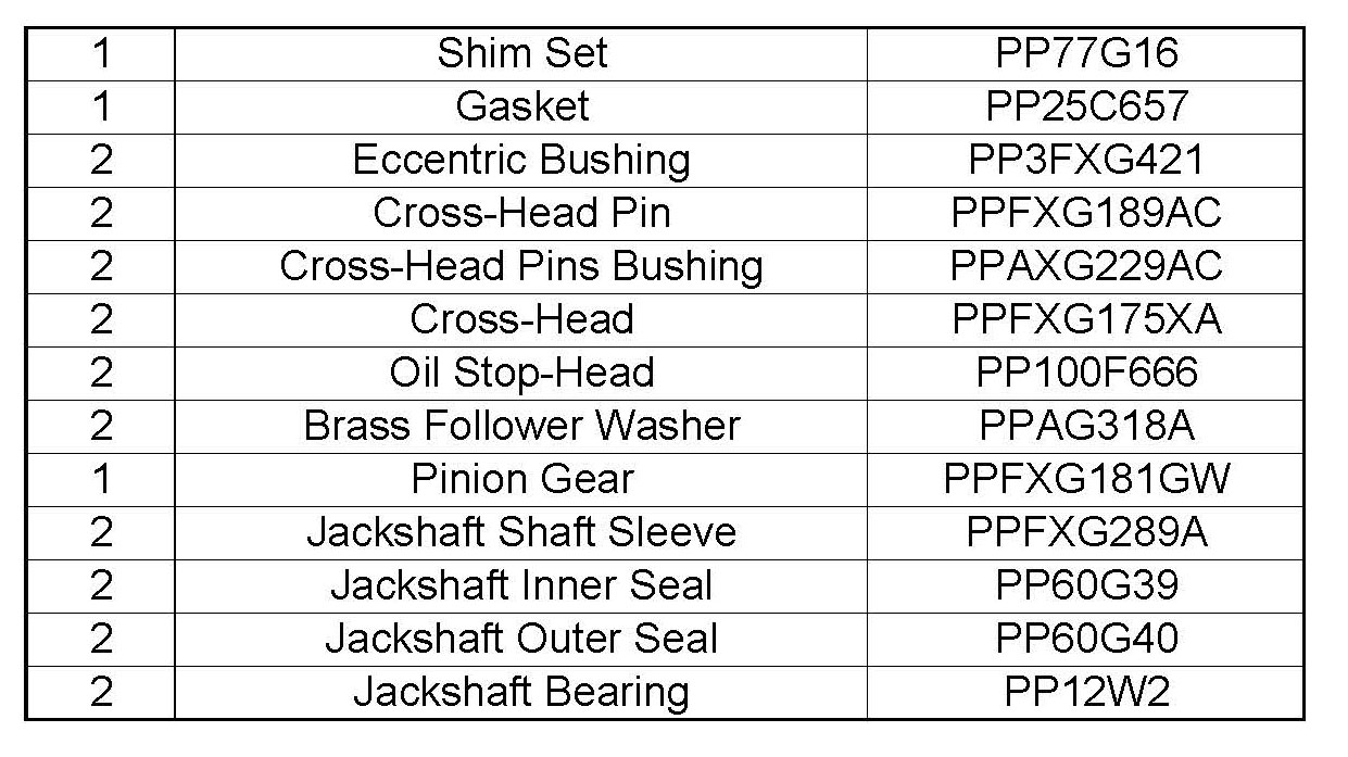
Order by Part Number and Description. Reference Numbers are for your convenience only.DRIVE PARTSRef.No. Name of Part Qty. Part No.Ref.No. Name of Part Qty. Part No.15–517 Page 71 JACKSHAFT . . . . . . . . . . . . . . . . . . . . . . . . . . . . . . . . 1 200PZL3712 KEY–JACKSHAFT . . . . . . . . . . . . . . . . . . . . . . . . . . . 1 200PZL0623 SPACER, Jackshaft Bearing . . . . . . . . . . . . . . . . . . . 2 GXH6494 SLEEVE–WEAR . . . . . . . . . . . . . . . . . . . . . . . . . . . . . 2 80M35 GASKET, Bearing Housing to Frame . . . . . . . . . . . . 2 25BC116 HOUSING–BEARING . . . . . . . . . . . . . . . . . . . . . . . . . 2 200PZL0067 SCREW, Bearing Housig to Frame . . . . . . . . . . . . . . 16 75A528 BEARING–ROLLER, Jackshaft . . . . . . . . . . . . . . . . 2 12W739 GASKET, Retainer Plate to Bearing Housing . . . . . 2 25BC1210 PLATE, Bearing Retainer . . . . . . . . . . . . . . . . . . . . . . 2 201PZL25312 SCREW, Retainer Plate to Bearing Housing . . . . . . 16 655EG07013 SEAL–OIL . . . . . . . . . . . . . . . . . . . . . . . . . . . . . . . . . . . 2 60DD1314 ECCENTRIC . . . . . . . . . . . . . . . . . . . . . . . . . . . . . . . . 1 200PZL25515 GEAR–DRIVEN . . . . . . . . . . . . . . . . . . . . . . . . . . . . . . 1 200PZL28016 SCREW, Gear to Eccentric . . . . . . . . . . . . . . . . . . . . 12 200PZL65517 WIRE . . . . . . . . . . . . . . . . . . . . . . . . . . . . . . . . . . . . . . . 144” 97A2918 BEARING–ROLLER, Eccentric . . . . . . . . . . . . . . . . . 2 12BA419 SHIM (.002) . . . . . . . . . . . . . . . . . . . . . . . . . . . . . . . . . 6 201PZL73220 SHIM (.005) . . . . . . . . . . . . . . . . . . . . . . . . . . . . . . . . . 6 202PZL73221 SHIM (.007) . . . . . . . . . . . . . . . . . . . . . . . . . . . . . . . . . 6 203PZL73222 SHIM (.020) . . . . . . . . . . . . . . . . . . . . . . . . . . . . . . . . . 8 204PZL73223 PLATE–RETAINER, Eccentric Bearing . . . . . . . . . . 2 200PZL16824 SCREW, Retainer to Eccentric . . . . . . . . . . . . . . . . . 16 75B14825 WIRE . . . . . . . . . . . . . . . . . . . . . . . . . . . . . . . . . . . . . . . 48” 97A2927 CONNECTING ROD, Includes ReferenceNumbers 28 & 29 . . . . . . . . . . . . . . . . . . . . . . . . . . 3 200PZL00328 BOLT–CONNECTING ROD . . . . . . . . . . . . . . . . . . . 6 PZ89029 NUT, Connecting Rod Bolt . . . . . . . . . . . . . . . . . . . . . 6 50B3430 LOCKNUT, Connecting Rod Bolt . . . . . . . . . . . . . . . 6 50M331 BEARING, Connecting Rod to Eccentric . . . . . . . . . 3 12BA632 RING–RETAINING, Connecting Rod Bearing . . . . . 1 74D533 PLATE–RETAINING, Bearing to Eccentric . . . . . . . 14 1PZ140034 SCREW, Bearing to Eccentric . . . . . . . . . . . . . . . . . . 14 655EF05D35 WIRE . . . . . . . . . . . . . . . . . . . . . . . . . . . . . . . . . . . . . . . 672” 97A2936 PLATE–RETAINING, Bearing to Connecting Rod . 22 PZ140036A PLATE–RETAINING, Bearing to Connecting Rod . 2 203PZL25337 SCREW, Bearing to Connecting Rod . . . . . . . . . . . . 48 75B4138 WIRE . . . . . . . . . . . . . . . . . . . . . . . . . . . . . . . . . . . . . . . 288” 97A2939 BEARING–ROLLER, Crosshead Pin . . . . . . . . . . . . 3 12BA540 PIN–LOCK . . . . . . . . . . . . . . . . . . . . . . . . . . . . . . . . . . 3 PZ83841 SET SCREW . . . . . . . . . . . . . . . . . . . . . . . . . . . . . . . . 3 76F1042 CROSSHEAD . . . . . . . . . . . . . . . . . . . . . . . . . . . . . . . 3 200PZL00543 PIN–CROSSHEAD . . . . . . . . . . . . . . . . . . . . . . . . . . . 3 200PZL18943A RING–RETAINING, Bearing . . . . . . . . . . . . . . . . . . . 3 200PZL70644 PLATE–RETAINER, Crosshead Pin . . . . . . . . . . . . . 3 206PZL16845 SCREW, Crosshead Pin Retainer . . . . . . . . . . . . . . . 24 75AG1746 WIRE . . . . . . . . . . . . . . . . . . . . . . . . . . . . . . . . . . . . . . . 12” 97A2947 ROD–EXTENSION . . . . . . . . . . . . . . . . . . . . . . . . . . . 3 200PZL83948 SCREW, Rod to Crosshead . . . . . . . . . . . . . . . . . . . . 18 PV70149 WIRE . . . . . . . . . . . . . . . . . . . . . . . . . . . . . . . . . . . . . . . 288” 97A2950 PLATE–RETAINER, Oil Stop Head to Frame . . . . . 6 202PZL16851 GASKET, Oil Stop Head . . . . . . . . . . . . . . . . . . . . . . . 3 25BC1352 HEAD–OIL STOP . . . . . . . . . . . . . . . . . . . . . . . . . . . . 3 200PZL05153 GASKET . . . . . . . . . . . . . . . . . . . . . . . . . . . . . . . . . . . . 24 25F954 SCREW, Oil Stop Head to Frame . . . . . . . . . . . . . . . 24 655EE08055 SEAL, Oil Stop Head . . . . . . . . . . . . . . . . . . . . . . . . . 6 201187256 RING–RETAINER, Oil Stop Head Seal . . . . . . . . . . 6 1PV139857 SCREW, Seal Retainer to Oil Stop Head . . . . . . . . . 18 75A10258 BAFFLE–ROD . . . . . . . . . . . . . . . . . . . . . . . . . . . . . . . 3 PZ840* ADAPTOR, For Rotating Shaft . . . . . . . . . . . . . . . . . 1 2PO1398* SCREW, Adaptor to Shaft . . . . . . . . . . . . . . . . . . . . . 2 655EF050* Not shown.
Order by Part Number and Description. Reference Numbers are for your convenience only.D74881PISTON LUBRICATING PUMPRef.No. Name of Part Qty. Part No.PUMP ASSEMBLY, Includes All Parts Shown . . . . . . . . . . . . . . . . . . . . . . .CA1221 CASING . . . . . . . . . . . . . . . . . . . . . . . . . . . . . . . . . . . . . . . . . . . . . . . . . . . . . . . . 1 C1K2A12 PLUG–SqHd PIPE . . . . . . . . . . . . . . . . . . . . . . . . . . . . . . . . . . . . . . . . . . . . . . . 2 64AA63 COCK, Drain . . . . . . . . . . . . . . . . . . . . . . . . . . . . . . . . . . . . . . . . . . . . . . . . . . . . 1 90C314 IMPELLER ASSEMBLY, SHAFT & PIN . . . . . . . . . . . . . . . . . . . . . . . . . . . . . 1 C1K1A1A5 KEY . . . . . . . . . . . . . . . . . . . . . . . . . . . . . . . . . . . . . . . . . . . . . . . . . . . . . . . . . . . 1 35B46 SEAL . . . . . . . . . . . . . . . . . . . . . . . . . . . . . . . . . . . . . . . . . . . . . . . . . . . . . . . . . . 1 60BT118 GASKET . . . . . . . . . . . . . . . . . . . . . . . . . . . . . . . . . . . . . . . . . . . . . . . . . . . . . . . 1 25D2129 FRAME . . . . . . . . . . . . . . . . . . . . . . . . . . . . . . . . . . . . . . . . . . . . . . . . . . . . . . . . 1 C1H4A210 SCREW . . . . . . . . . . . . . . . . . . . . . . . . . . . . . . . . . . . . . . . . . . . . . . . . . . . . . . . . 8 75A13011 BEARING–BALL (Inner) Includes Retaining Ring . . . . . . . . . . . . . . . . . . . . 1 12AK312 BEARING–BALL (Outer) Includes Retaining Ring . . . . . . . . . . . . . . . . . . . 1 12AK315–517 Page 16
Order by Part Number and Description. Reference Numbers are for your convenience only.300PAH810(Ref. Drawing)OIL CIRCULATING PUMPRef.No. Name of Part Qty. Part No.OIL PUMP – COMPLETE . . . . . . . . . . . . . . . . . . . . . . . . . . . . . . . . . . . . . . . . . 1 201PAH1881 COVER . . . . . . . . . . . . . . . . . . . . . . . . . . . . . . . . . . . . . . . . . . . . . . . . . . . . . . . . . 1 20109872 WASHER . . . . . . . . . . . . . . . . . . . . . . . . . . . . . . . . . . . . . . . . . . . . . . . . . . . . . . . 1 20109923 BALL BEARING . . . . . . . . . . . . . . . . . . . . . . . . . . . . . . . . . . . . . . . . . . . . . . . . . 1 20109934 SHIM, Bearing . . . . . . . . . . . . . . . . . . . . . . . . . . . . . . . . . . . . . . . . . . . . . . . . . . . 1 20109945 ROTOR . . . . . . . . . . . . . . . . . . . . . . . . . . . . . . . . . . . . . . . . . . . . . . . . . . . . . . . . . 1 20109956 WASHER . . . . . . . . . . . . . . . . . . . . . . . . . . . . . . . . . . . . . . . . . . . . . . . . . . . . . . . 1 20109967 SEAL, Mechanical . . . . . . . . . . . . . . . . . . . . . . . . . . . . . . . . . . . . . . . . . . . . . . . . 1 21090038 O–RING . . . . . . . . . . . . . . . . . . . . . . . . . . . . . . . . . . . . . . . . . . . . . . . . . . . . . . . . 1 21090049 PLUG–HOUSING . . . . . . . . . . . . . . . . . . . . . . . . . . . . . . . . . . . . . . . . . . . . . . . . 1 201099710 HOUSING–BEARING . . . . . . . . . . . . . . . . . . . . . . . . . . . . . . . . . . . . . . . . . . . . 1 210900511 SEAL, Bearing Housing . . . . . . . . . . . . . . . . . . . . . . . . . . . . . . . . . . . . . . . . . . . 1 201099812 BEARING–ROLLER . . . . . . . . . . . . . . . . . . . . . . . . . . . . . . . . . . . . . . . . . . . . . . 1 2010999* VENT PLUG–SUCTION . . . . . . . . . . . . . . . . . . . . . . . . . . . . . . . . . . . . . . . . . . 1 2109000* VENT PLUG–DISCHARGE . . . . . . . . . . . . . . . . . . . . . . . . . . . . . . . . . . . . . . . . 1 2109001* WASHER, Vent Plug . . . . . . . . . . . . . . . . . . . . . . . . . . . . . . . . . . . . . . . . . . . . . . 2 2109002* Not shown.15–517 Page 17
Order by Part Number and Description. Reference Numbers are for your convenience only.OIL PUMP & PIPINGRef.No. Name of Part Qty. Part No.Ref.No. Name of Part Qty. Part No.15–517 Page 191 SCREEN–OIL . . . . . . . . . . . . . . . . . . . . . . . . . . . . . . . 1 3WAJ5112 ELBOW . . . . . . . . . . . . . . . . . . . . . . . . . . . . . . . . . . . . . 1 64C83 NIPPLE . . . . . . . . . . . . . . . . . . . . . . . . . . . . . . . . . . . . . 1 63U24X164 ELBOW . . . . . . . . . . . . . . . . . . . . . . . . . . . . . . . . . . . . . 1 64U49 PUMP–OIL** . . . . . . . . . . . . . . . . . . . . . . . . . . . . . . . . 1 201PAH18810 SCREW . . . . . . . . . . . . . . . . . . . . . . . . . . . . . . . . . . . . . 4 75A35N11 KEY . . . . . . . . . . . . . . . . . . . . . . . . . . . . . . . . . . . . . . . . 1 35D212 ADAPTOR, Oil Pump . . . . . . . . . . . . . . . . . . . . . . . . . 1 200PZL17013 PLATE, Oil Pump to Frame . . . . . . . . . . . . . . . . . . . . 1 PY52614 SCREW, Adaptor to Frame . . . . . . . . . . . . . . . . . . . . 4 655ED05D15 BUSHING–HUB, Gear . . . . . . . . . . . . . . . . . . . . . . . . 1 22F12SD16 GEAR–DRIVEN, Oil Pump . . . . . . . . . . . . . . . . . . . . 1 201PZL280* WIRE . . . . . . . . . . . . . . . . . . . . . . . . . . . . . . . . . . . . . . . 24” 97A29(Pump Discharge to Filter)20 ADAPTOR–HOSE . . . . . . . . . . . . . . . . . . . . . . . . . . . . 1 29Q1721 HYDRAULIC HOSE ASSEMBLY . . . . . . . . . . . . . . . 1 29R2122 TEE . . . . . . . . . . . . . . . . . . . . . . . . . . . . . . . . . . . . . . . . 1 64G723 VALVE–LIQUID RELIEF . . . . . . . . . . . . . . . . . . . . . . . 1 90Q6224 NIPPLE . . . . . . . . . . . . . . . . . . . . . . . . . . . . . . . . . . . . . 1 63U12X1625 UNION–STRAIGHT . . . . . . . . . . . . . . . . . . . . . . . . . . 1 64Z1026 NIPPLE . . . . . . . . . . . . . . . . . . . . . . . . . . . . . . . . . . . . . 1 63U12X3427 FILTER–OIL*** . . . . . . . . . . . . . . . . . . . . . . . . . . . . . . . 1 26C18(Filter to Crosshead Spray)28 NIPPLE . . . . . . . . . . . . . . . . . . . . . . . . . . . . . . . . . . . . . 1 63U12X1328A NIPPLE . . . . . . . . . . . . . . . . . . . . . . . . . . . . . . . . . . . . . 1 63U12X2229 ELBOW . . . . . . . . . . . . . . . . . . . . . . . . . . . . . . . . . . . . . 2 64C530 NIPPLE . . . . . . . . . . . . . . . . . . . . . . . . . . . . . . . . . . . . . 1 63U12X8031 TEE . . . . . . . . . . . . . . . . . . . . . . . . . . . . . . . . . . . . . . . . 1 64G732 REDUCER–PIPE . . . . . . . . . . . . . . . . . . . . . . . . . . . . . 1 64N2533 HYDRAULIC HOSE ASSEMBLY . . . . . . . . . . . . . . . 1 29Z2634 CLAMP, Hose . . . . . . . . . . . . . . . . . . . . . . . . . . . . . . . . 2 98H435 WASHER, Clamp . . . . . . . . . . . . . . . . . . . . . . . . . . . . 2 95B136 SCREW, Hose Clamp . . . . . . . . . . . . . . . . . . . . . . . . . 2 655EC03037 TEE . . . . . . . . . . . . . . . . . . . . . . . . . . . . . . . . . . . . . . . . 5 64G638 NIPPLE . . . . . . . . . . . . . . . . . . . . . . . . . . . . . . . . . . . . . 3 63F2139 ELBOW . . . . . . . . . . . . . . . . . . . . . . . . . . . . . . . . . . . . . 2 64C440 NIPPLE . . . . . . . . . . . . . . . . . . . . . . . . . . . . . . . . . . . . . 3 63N8X16041 BUSHING–PIPE . . . . . . . . . . . . . . . . . . . . . . . . . . . . . 6 64E2342 ELBOW . . . . . . . . . . . . . . . . . . . . . . . . . . . . . . . . . . . . . 6 64X143 NOZZLE . . . . . . . . . . . . . . . . . . . . . . . . . . . . . . . . . . . . 6 200998244 CLAMP . . . . . . . . . . . . . . . . . . . . . . . . . . . . . . . . . . . . . 2 200PZL65445 STUD . . . . . . . . . . . . . . . . . . . . . . . . . . . . . . . . . . . . . . . 2 79H146 NUT . . . . . . . . . . . . . . . . . . . . . . . . . . . . . . . . . . . . . . . . 2 50B547 LOCKNUT . . . . . . . . . . . . . . . . . . . . . . . . . . . . . . . . . . 2 50V44(Filter Tee to Trough)48 BUSHING–PIPE . . . . . . . . . . . . . . . . . . . . . . . . . . . . . 3 64E9549 NIPPLE . . . . . . . . . . . . . . . . . . . . . . . . . . . . . . . . . . . . . 1 63V8X1150 ADAPTOR–HOSE . . . . . . . . . . . . . . . . . . . . . . . . . . . . 2 29Q651 HYDRAULIC HOSE ASSEMBLY . . . . . . . . . . . . . . . 1 29Z8152 CLAMP, Hose to Frame . . . . . . . . . . . . . . . . . . . . . . . 5 PZ130153 SCREW, Clamp . . . . . . . . . . . . . . . . . . . . . . . . . . . . . . 1 655ED02054 ADAPTOR–HOSE . . . . . . . . . . . . . . . . . . . . . . . . . . . . 2 29Q1755 ELBOW . . . . . . . . . . . . . . . . . . . . . . . . . . . . . . . . . . . . . 1 64C5(Oil Trough to Main Bearing)56 TROUGH, Oil Feed . . . . . . . . . . . . . . . . . . . . . . . . . . . 1 201PZL12557 SCREW, Trough to Frame . . . . . . . . . . . . . . . . . . . . . 2 655EF04058 ADAPTOR–HOSE . . . . . . . . . . . . . . . . . . . . . . . . . . . . 2 29Q5459 HYDRAULIC HOSE ASSEMBLY . . . . . . . . . . . . . . . 2 29Z3560 NIPPLE, Trough to Jackshaft . . . . . . . . . . . . . . . . . . 2 63AJ6X13061 TROUGH, Jackshaft Bearing Oil . . . . . . . . . . . . . . . 2 202PZL12562 SCREW, Jackshaft Bearing Oil Trough . . . . . . . . . . 6 655EE03D* ELBOW, Hose to Bearing . . . . . . . . . . . . . . . . . . . . . . 2 64D4* WIRE . . . . . . . . . . . . . . . . . . . . . . . . . . . . . . . . . . . . . . . 96” 97A29* BUSHING–PIPE . . . . . . . . . . . . . . . . . . . . . . . . . . . . . 1 64E36* Not shown.** For Oil Pump and Component Parts See Page 17*** For Oil Filter and Component Parts See Page 25
Order by Part Number and Description. Reference Numbers are for your convenience only.PISTON LUBRICATING PIPING(General Service)Ref.No. Name of Part Qty. Part No.Ref.No. Name of Part Qty. Part No.15–517 Page 211 SCREEN–OIL . . . . . . . . . . . . . . . . . . . . . . . 1 2WAJ5112 NIPPLE . . . . . . . . . . . . . . . . . . . . . . . . . . . . 1 63H253 UNION–HAMMER, Wing . . . . . . . . . . . . . 1 64EB14 NIPPLE . . . . . . . . . . . . . . . . . . . . . . . . . . . . 1 63H255 VALVE . . . . . . . . . . . . . . . . . . . . . . . . . . . . . 1 90A366 NIPPLE . . . . . . . . . . . . . . . . . . . . . . . . . . . . 1 63H257 TEE . . . . . . . . . . . . . . . . . . . . . . . . . . . . . . . . 1 64G8G8 NIPPLE . . . . . . . . . . . . . . . . . . . . . . . . . . . . 1 63H259 VALVE . . . . . . . . . . . . . . . . . . . . . . . . . . . . . 1 90A3610 ADAPTOR–HOSE . . . . . . . . . . . . . . . . . . . 1 29Q911 HYDRAULIC HOSE ASSEMBLY . . . . . . . 1 29Z712 PUMP PISTON LUBRICATING,**Includes Reference Number 13 . . . . . . 1 CA12213 KEY . . . . . . . . . . . . . . . . . . . . . . . . . . . . . . . . 1 35B414 SCREW, Pump to Skid . . . . . . . . . . . . . . . 4 655ED04015 LOCKWASHER, Pump to Skid . . . . . . . . 4 95B316 WASHER, Pump to Skid . . . . . . . . . . . . . . 4 95A317 SHEAVE . . . . . . . . . . . . . . . . . . . . . . . . . . . . 1 73K1A3018 BUSHING–HUB . . . . . . . . . . . . . . . . . . . . . 1 22E16B19 BELT . . . . . . . . . . . . . . . . . . . . . . . . . . . . . . . 1 13C7920 AUXILIARY SHEAVE ASSEMBLY . . . . . 1 200PZL195A* SET SCREW, Sheave . . . . . . . . . . . . . . . . 2 76F30(Pump to Liner Group)21 ADAPTOR–HOSE . . . . . . . . . . . . . . . . . . . 1 29Q1022 HYDRAULIC HOSE ASSEMBLY . . . . . . . 1 200927023 ADAPTOR–HOSE . . . . . . . . . . . . . . . . . . . 1 29Q2724 REDUCER–PIPE . . . . . . . . . . . . . . . . . . . . 1 64N325 VALVE . . . . . . . . . . . . . . . . . . . . . . . . . . . . . 1 90A2526 ELBOW . . . . . . . . . . . . . . . . . . . . . . . . . . . . 1 64C527 NIPPLE . . . . . . . . . . . . . . . . . . . . . . . . . . . . 1 63G928 TEE . . . . . . . . . . . . . . . . . . . . . . . . . . . . . . . . 1 64P3929 CLAMP . . . . . . . . . . . . . . . . . . . . . . . . . . . . . 2 98H530 WASHER . . . . . . . . . . . . . . . . . . . . . . . . . . . 2 95B331 SCREW . . . . . . . . . . . . . . . . . . . . . . . . . . . . 2 75A6832 NIPPLE . . . . . . . . . . . . . . . . . . . . . . . . . . . . 1 63N12X18433 TEE . . . . . . . . . . . . . . . . . . . . . . . . . . . . . . . . 1 64P3934 NIPPLE . . . . . . . . . . . . . . . . . . . . . . . . . . . . 1 63N12X18435 TEE . . . . . . . . . . . . . . . . . . . . . . . . . . . . . . . . 1 64P3936 PLUG . . . . . . . . . . . . . . . . . . . . . . . . . . . . . . 1 64A537 HYDRAULIC HOSE ASSEMBLY . . . . . . . 3 29R3238 ADAPTOR–HOSE . . . . . . . . . . . . . . . . . . . 3 29Q8339 COUPLING–PIPE . . . . . . . . . . . . . . . . . . . 3 64BK340 BAFFLE . . . . . . . . . . . . . . . . . . . . . . . . . . . . 3 200PZL84041 NUT–ACORN . . . . . . . . . . . . . . . . . . . . . . . 6 50Q30(Frame to Lube Oil Tank Group)42 NIPPLE . . . . . . . . . . . . . . . . . . . . . . . . . . . . 1 63L2843 ELBOW . . . . . . . . . . . . . . . . . . . . . . . . . . . . 1 64C944 TANK–LUBE OIL . . . . . . . . . . . . . . . . . . . . 1 200PZL25045 PLUG . . . . . . . . . . . . . . . . . . . . . . . . . . . . . . 2 64A746 SCREW, Lube Tank to Skid . . . . . . . . . . . 4 655EE04047 WASHER . . . . . . . . . . . . . . . . . . . . . . . . . . . 4 95A548 PLUG . . . . . . . . . . . . . . . . . . . . . . . . . . . . . . 1 64A649 COVER–LUBE OIL TANK . . . . . . . . . . . . . 1 201265550 NUT–WING . . . . . . . . . . . . . . . . . . . . . . . . . 2 50H1* NIPPLE . . . . . . . . . . . . . . . . . . . . . . . . . . . . 1 63AJ32X60* Not shown.** For Piston Lubricating Pump and Components Parts See Page 16.
Order by Part Number and Description. Reference Numbers are for your convenience only.PISTON LUBRICATING PIPING(High Pressure Service)Ref.No. Name of Part Qty. Part No.Ref.No. Name of Part Qty. Part No.15–517 Page 231 SCREEN–OIL . . . . . . . . . . . . . . . . . . . . . . . . . . . . . . . 1 2WAJ5112 NIPPLE . . . . . . . . . . . . . . . . . . . . . . . . . . . . . . . . . . . . . 1 63H253 UNION–HAMMER, Wing . . . . . . . . . . . . . . . . . . . . . . 1 64EB14 NIPPLE . . . . . . . . . . . . . . . . . . . . . . . . . . . . . . . . . . . . . 1 63H255 VALVE . . . . . . . . . . . . . . . . . . . . . . . . . . . . . . . . . . . . . . 1 90A366 NIPPLE . . . . . . . . . . . . . . . . . . . . . . . . . . . . . . . . . . . . . 1 63H257 TEE . . . . . . . . . . . . . . . . . . . . . . . . . . . . . . . . . . . . . . . . 1 64G8G8 NIPPLE . . . . . . . . . . . . . . . . . . . . . . . . . . . . . . . . . . . . . 1 63H259 VALVE . . . . . . . . . . . . . . . . . . . . . . . . . . . . . . . . . . . . . . 1 90A3610 ADAPTOR–HOSE . . . . . . . . . . . . . . . . . . . . . . . . . . . . 1 29Q911 HYDRAULIC HOSE ASSEMBLY . . . . . . . . . . . . . . . 1 29Z712 PUMP PISTON LUBRICATING,** IncludesReference Number 13 . . . . . . . . . . . . . . . . . . . . . . 1 CA12213 KEY . . . . . . . . . . . . . . . . . . . . . . . . . . . . . . . . . . . . . . . . 1 35B414 SCREW, Pump to Skid . . . . . . . . . . . . . . . . . . . . . . . . 4 655ED04015 LOCKWASHER, Pump to Skid . . . . . . . . . . . . . . . . . 4 95B316 WASHER, Pump to Skid . . . . . . . . . . . . . . . . . . . . . . 4 95A317 SHEAVE . . . . . . . . . . . . . . . . . . . . . . . . . . . . . . . . . . . . 1 73K1A3018 BUSHING–HUB . . . . . . . . . . . . . . . . . . . . . . . . . . . . . . 1 22E16B19 BELT . . . . . . . . . . . . . . . . . . . . . . . . . . . . . . . . . . . . . . . 1 13C7920 AUXILIARY SHEAVE ASSEMBLY . . . . . . . . . . . . . . 1 200PZL195A* SET SCREW, Sheave . . . . . . . . . . . . . . . . . . . . . . . . 2 76F30(Pump to Liner Group)21 ADAPTOR–HOSE . . . . . . . . . . . . . . . . . . . . . . . . . . . . 1 29Q1022 HYDRAULIC HOSE ASSEMBLY . . . . . . . . . . . . . . . 1 200927023 ADAPTOR–HOSE . . . . . . . . . . . . . . . . . . . . . . . . . . . . 1 29Q2724 REDUCER–PIPE . . . . . . . . . . . . . . . . . . . . . . . . . . . . . 1 64N325 VALVE . . . . . . . . . . . . . . . . . . . . . . . . . . . . . . . . . . . . . . 1 90A2526 ELBOW . . . . . . . . . . . . . . . . . . . . . . . . . . . . . . . . . . . . . 1 64C527 NIPPLE . . . . . . . . . . . . . . . . . . . . . . . . . . . . . . . . . . . . . 1 63N12X20028 TEE–PIPE . . . . . . . . . . . . . . . . . . . . . . . . . . . . . . . . . . 1 64P3929 NIPPLE . . . . . . . . . . . . . . . . . . . . . . . . . . . . . . . . . . . . . 1 63N12X19030 TEE–PIPE . . . . . . . . . . . . . . . . . . . . . . . . . . . . . . . . . . 1 64P3931 NIPPLE . . . . . . . . . . . . . . . . . . . . . . . . . . . . . . . . . . . . . 1 63N12X20032 NIPPLE . . . . . . . . . . . . . . . . . . . . . . . . . . . . . . . . . . . . . 1 63G1933 TEE . . . . . . . . . . . . . . . . . . . . . . . . . . . . . . . . . . . . . . . . 1 64P3934 CAP–PIPE . . . . . . . . . . . . . . . . . . . . . . . . . . . . . . . . . . 1 64AD535 ADAPTOR–HOSE . . . . . . . . . . . . . . . . . . . . . . . . . . . . 3 29Q636 HYDRAULIC HOSE ASSEMBLY . . . . . . . . . . . . . . . 3 29R2937 ELBOW . . . . . . . . . . . . . . . . . . . . . . . . . . . . . . . . . . . . . 3 64C438 NIPPLE . . . . . . . . . . . . . . . . . . . . . . . . . . . . . . . . . . . . . 3 63F639 ELBOW . . . . . . . . . . . . . . . . . . . . . . . . . . . . . . . . . . . . . 3 64C440 NIPPLE . . . . . . . . . . . . . . . . . . . . . . . . . . . . . . . . . . . . . 3 63F3341 BRACKET . . . . . . . . . . . . . . . . . . . . . . . . . . . . . . . . . . . 3 300PZL017(Frame to Lube Oil Tank Group)42 NIPPLE . . . . . . . . . . . . . . . . . . . . . . . . . . . . . . . . . . . . . 1 63L2843 ELBOW . . . . . . . . . . . . . . . . . . . . . . . . . . . . . . . . . . . . . 1 64C944 TANK–LUBE OIL . . . . . . . . . . . . . . . . . . . . . . . . . . . . . 1 200PZL25045 PLUG . . . . . . . . . . . . . . . . . . . . . . . . . . . . . . . . . . . . . . . 2 64A746 SCREW, Lube Tank to Skid . . . . . . . . . . . . . . . . . . . . 4 655EE04047 WASHER . . . . . . . . . . . . . . . . . . . . . . . . . . . . . . . . . . . 4 95A548 PLUG . . . . . . . . . . . . . . . . . . . . . . . . . . . . . . . . . . . . . . . 1 64A649 COVER–LUBE OIL TANK . . . . . . . . . . . . . . . . . . . . . 1 201265550 NUT–WING . . . . . . . . . . . . . . . . . . . . . . . . . . . . . . . . . 2 50H151 FITTING–TUBE . . . . . . . . . . . . . . . . . . . . . . . . . . . . . . 3 86M1852 TUBE–FORMED . . . . . . . . . . . . . . . . . . . . . . . . . . . . . 3 300PZL85753 CAP–BAFFLE . . . . . . . . . . . . . . . . . . . . . . . . . . . . . . . 3 300PZL23754 RING–WATER DISTRIBUTION . . . . . . . . . . . . . . . . 3 300PZL46155 U–BOLT . . . . . . . . . . . . . . . . . . . . . . . . . . . . . . . . . . . . 6 12368456 LOCKWASHER . . . . . . . . . . . . . . . . . . . . . . . . . . . . . . 4 95B357 NUT . . . . . . . . . . . . . . . . . . . . . . . . . . . . . . . . . . . . . . . . 4 50AQ358 SCREW . . . . . . . . . . . . . . . . . . . . . . . . . . . . . . . . . . . . . 6 655ED04059 LOCKWASHER . . . . . . . . . . . . . . . . . . . . . . . . . . . . . . 6 95B360 BRACKET–WASH PIPE . . . . . . . . . . . . . . . . . . . . . . . 2 301PZL01761 SCREW–FLANGE HEAD . . . . . . . . . . . . . . . . . . . . . 6 75LM150* NIPPLE . . . . . . . . . . . . . . . . . . . . . . . . . . . . . . . . . . . . 1 63AJ32X60* Not shown.** For Piston Lubricating Pump and Components Parts See Page 16.
Order by Part Number and Description. Reference Numbers are for your convenience only.VALVE SEAT PULLER(OPTIONAL EQUIPMENT)Center FullRef. Guided OpeningNo. Name of Part Qty. Part No. Part No.1 HEAD (Not Included with 100E12 Puller) . . . . . . . . . . . . . . 1 100E13 ** 300PZL219VALVE SEAT PULLER ASSEMBLY, Includes ReferenceNumbers 2 thru 11 . . . . . . . . . . . . . . . . . . . . . . . . . . . . . . . 1 100E12 100E122 HYDRAULIC JACK . . . . . . . . . . . . . . . . . . . . . . . . . . . . . . . . . 1 2116728 21167283 CENTER STEM . . . . . . . . . . . . . . . . . . . . . . . . . . . . . . . . . . . . 1 2117314 21173144 CENTER STEM NUT . . . . . . . . . . . . . . . . . . . . . . . . . . . . . . . 1 2117315 21173155 PULLER H BAR BASE . . . . . . . . . . . . . . . . . . . . . . . . . . . . . . 1 2116727 21167276 CENTER BUSHING . . . . . . . . . . . . . . . . . . . . . . . . . . . . . . . . 1 2117316 2117316* CENTER BUSHING . . . . . . . . . . . . . . . . . . . . . . . . . . . . . . . . 1 2117317 21173177 HYDRAULIC HOSE . . . . . . . . . . . . . . . . . . . . . . . . . . . . . . . . . 1 2117318 21173188 HYDRAULIC PUMP . . . . . . . . . . . . . . . . . . . . . . . . . . . . . . . . 1 2117319 21173199 GAUGE ADAPTOR . . . . . . . . . . . . . . . . . . . . . . . . . . . . . . . . . 1 2117320 211732010 GAUGE COUPLER . . . . . . . . . . . . . . . . . . . . . . . . . . . . . . . . . 1 2117321 2117321* GAUGE COUPLER . . . . . . . . . . . . . . . . . . . . . . . . . . . . . . . . . 1 2117322 211732211 GAUGE 170 TON . . . . . . . . . . . . . . . . . . . . . . . . . . . . . . . . . . 1 2117323 2117323* CARRYING CASE . . . . . . . . . . . . . . . . . . . . . . . . . . . . . . . . . . 1 2117055 2117055* Not shown.** Shown on Drawing.15–517 Page 26
GARDNER DENVER UNIT RECORDThe following unit identification plate is provided as a convenience to you, our valued GardnerDenver customer. Please take the time to copy all the information from the actual nameplate ofyour unit. The model number, date manufactured and serial number will be required whencontacting the company or your distributor for information or replacement parts.200OPA496(Ref. Drawing)

Permian Pump & Power stocks and sources OEM and aftermarket power end parts for most major power pump brands. If we don’t have the parts on the shelf, here in Odessa Texas, we can source them through other vendors in our vast network of suppliers nationwide.
PPP offers most used, rebuilt and new power end pump parts for sale, including main bearings, rod bearings, crankshafts, wrist pins, bushings, connecting rods and seals and gaskets.

AfghanistanAlbaniaAlgeriaAmerican SamoaAndorraAngolaAnguillaAntarcticaAntigua and BarbudaArgentinaArmeniaArubaAustraliaAustriaAzerbaijanBahamasBahrainBangladeshBarbadosBelarusBelgiumBelizeBeninBermudaBhutanBoliviaBonaire, Sint Eustatius and SabaBosnia and HerzegovinaBotswanaBouvet IslandBrazilBritish Indian Ocean TerritoryBrunei DarussalamBulgariaBurkina FasoBurundiCabo VerdeCambodiaCameroonCanadaCayman IslandsCentral African RepublicChadChileChinaChristmas IslandCocos IslandsColombiaComorosCongoCongo, Democratic Republic of theCook IslandsCosta RicaCroatiaCubaCuraçaoCyprusCzechiaCôte d"IvoireDenmarkDjiboutiDominicaDominican RepublicEcuadorEgyptEl SalvadorEquatorial GuineaEritreaEstoniaEswatiniEthiopiaFalkland IslandsFaroe IslandsFijiFinlandFranceFrench GuianaFrench PolynesiaFrench Southern TerritoriesGabonGambiaGeorgiaGermanyGhanaGibraltarGreeceGreenlandGrenadaGuadeloupeGuamGuatemalaGuernseyGuineaGuinea-BissauGuyanaHaitiHeard Island and McDonald IslandsHoly SeeHondurasHong KongHungaryIcelandIndiaIndonesiaIranIraqIrelandIsle of ManIsraelItalyJamaicaJapanJerseyJordanKazakhstanKenyaKiribatiKorea, Democratic People"s Republic ofKorea, Republic ofKuwaitKyrgyzstanLao People"s Democratic RepublicLatviaLebanonLesothoLiberiaLibyaLiechtensteinLithuaniaLuxembourgMacaoMadagascarMalawiMalaysiaMaldivesMaliMaltaMarshall IslandsMartiniqueMauritaniaMauritiusMayotteMexicoMicronesiaMoldovaMonacoMongoliaMontenegroMontserratMoroccoMozambiqueMyanmarNamibiaNauruNepalNetherlandsNew CaledoniaNew ZealandNicaraguaNigerNigeriaNiueNorfolk IslandNorth MacedoniaNorthern Mariana IslandsNorwayOmanPakistanPalauPalestine, State ofPanamaPapua New GuineaParaguayPeruPhilippinesPitcairnPolandPortugalPuerto RicoQatarRomaniaRussian FederationRwandaRéunionSaint BarthélemySaint Helena, Ascension and Tristan da CunhaSaint Kitts and NevisSaint LuciaSaint MartinSaint Pierre and MiquelonSaint Vincent and the GrenadinesSamoaSan MarinoSao Tome and PrincipeSaudi ArabiaSenegalSerbiaSeychellesSierra LeoneSingaporeSint MaartenSlovakiaSloveniaSolomon IslandsSomaliaSouth AfricaSouth Georgia and the South Sandwich IslandsSouth SudanSpainSri LankaSudanSurinameSvalbard and Jan MayenSwedenSwitzerlandSyria Arab RepublicTaiwanTajikistanTanzania, the United Republic ofThailandTimor-LesteTogoTokelauTongaTrinidad and TobagoTunisiaTurkmenistanTurks and Caicos IslandsTuvaluTürkiyeUS Minor Outlying IslandsUgandaUkraineUnited Arab EmiratesUnited KingdomUnited StatesUruguayUzbekistanVanuatuVenezuelaViet NamVirgin Islands, BritishVirgin Islands, U.S.Wallis and FutunaWestern SaharaYemenZambiaZimbabweÅland Islands
Maintain Pump Reliability and Performance with Genuine Gardner Denver Parts andSupport Services .......................................................................................................................... 2 Instructions for Ordering Repair Parts ................................................................................. 2 Model Matrix .......................................................................................................2 Customer Service Locations ........................................................................................... 3
Section 1, Pump Danger Notices .................................................................................................. 6 Covers & Guards ............................................................................................................ 7 Equipment Moving & Lifting ............................................................................................ 7 Pressurized Pump Systems ............................................................................................ 8 Flammable, Hot, Cold, or Corrosive Fluid Pumping ........................................................ 9
Section 2, Centrifugal Pump Fundamentals .................................................................................. 10 Pressure Head ................................................................................................................ 12 Net Positive Suction Head .............................................................................................. 12 Parallel & Series Operations ........................................................................................... 14 Trouble Shooting ............................................................................................................ 15 Square Braided Packing ................................................................................................. 16 Oil Seal Packing ............................................................................................................. 17 Standard Torque Chart ................................................................................................... 18
Section 3, Maintenance ................................................................................................................ 19 Disassembly ................................................................................................................... 19 Replacing Front Wear Plate ............................................................................................ 28 Packing ........................................................................................................................... 31 Assembly ........................................................................................................................ 34 Additional Parts .............................................................................................................. 45
Section 4, Technical Data & Parts List .......................................................................................... 47 4” x 5” Technical Data ..................................................................................................... 47 4” x 5” Assembly ............................................................................................................. 49 4” x 5” Parts List ............................................................................................................. 50 5” x 6” Technical Data ..................................................................................................... 51 5” x 6” Assembly ............................................................................................................. 53 5” x 6” Parts List ............................................................................................................. 54
1 MAINTAIN PUMP RELIABILITY AND PERFORMANCE WITH GENUINE GARDNER DENVER PARTS AND SUPPORT SERVICES
Gardner Denver® genuine pump parts are manufactured to design tolerances and are developed foroptimum dependability. Design and material innovations are the result of years of experience withhundreds of different pump applications. Reliability in materials and quality assurance is incorporatedin our genuine replacement parts.
Your authorized Gardner Denver Sales Office offers all the backup you’ll need. The Fort WorthManufacturing Facility maintains a large inventory of genuine parts.
Gardner Denver supports your needs with these services:1. Trained parts specialists to assist you in selecting the correct replacement parts.2. Repair and maintenance kits designed with the necessary parts to simplify servicing your pump.Authorized service technicians are factory trained and skilled in pump maintenance and repair. Theyare ready to respond and assist you by providing fast, expert maintenance and repair services.
The pump model and serial number (see The name and address of your company nameplate on the unit.) Part number and description of the part. The name and telephone number of contact person. Part number and description of the part. Your purchase order or requisition number. Specify exactly the number of parts Complete shipping address (where the required (do not order by sets or parts are to be shipped. groups).
Altoona – Gardner Denver San Antonio – Gardner DenverWell Service Pump Sales, Srv & Repair Aftermarket Parts & Srv150 Enterprise Drive 8034 NE Loop 410Altoona, PA 16601 San Antonio, TX 78219817.742.9600 210.662.2806
Fort Worth – Gardner Denver Tulsa – Gardner DenverAftermarket Repairs, Parts, & Srv Well Service Pump Sales7533 Kathy Lane 4747 South 83rd East AvenueFort Worth, TX 76126 Tulsa, OK 74145800.824.0271 800.637.8099
Fort Worth – Gardner Denver Odessa – Gardner DenverCentral W arehouse Well Service Pump Sales, Srv, & Repair2600 Sylvania Cross Drive 8620 E Hwy 191Fort Worth, TX 76137 Odessa, TX 79765817.248.4500 432.366.5433
Fort Worth – Gardner Denver Drilling Pump Aftermarket – Gardner Denver441 Winscott Rd. Repair and SupportFort Worth, TX 76126 2121 West 44th Street817.249.6400. Odessa, TX 79764 1.866.GDPUMPSOklahoma City – Gardner DenverAftermarket Parts & Srv Quincy – Gardner Denver2200 South Prospect Drilling Pump SalesOklahoma City, OK 73129 1800 Gardner Expressway405.677.5736 Quincy, IL 62304 217.222.5400Dickenson – Gardner DenverAftermarket Parts & Srv Argentina – Gardner Denver Repair and Support380 26th St. Building E, Suite 100 Sublote 6, Lote 1, Manzana 6, 8300Dickenson, ND 58601 Neuquen, Argentina701.225.6148 Canada – Gardner DenverConroe- Gardner Denver Repair and SupportManufacturing and Repair #105 6303 39th Street1700 Orval Road Leduc, AB T9E6E8Conroe, TX 77301936.539.2005 Middle East – Gardner Denver Repair and SupportNorthern Alberta – Gardner Denver Gardner Denver FZERepair and Support Jafza Views 18 Office 6039608-69 Avenue Jebel Ali Free ZoneClairmont, AB TOH OWO Dubai, United Arab Emirates780.612.2600 971.4.881.1744
Permian Basin-Gardner Denver Pump Parts – Gardner DenverManufacturing, Repair, and Support Repair and Support8620 TX 191 East Odessa, TX 79765 178 Bearcat Rd,432.366.5433 Aledo, TX 76008 817.441.7787
Gardner Denver® pumps are the result of advanced engineering and skilled manufacturing. To beassured of receiving maximum service from this pump the owner must exercise care in its operationand maintenance. This book is written to give the operator and maintenance personnel essentialinformation for day-to-day operation, maintenance and adjustment. Careful adherence to theseinstructions will result in economical operation and minimal downtime.Gardner Denver Design Features Give Long Life & Easy Maintenance. A light weight, compact, 4”x5” Pump and a medium weight 5”x6” Pump are extremely rugged and require minimal mounting space. A heavy steel frame and mounting bracket for horizontal or vertical positioning. Every frame is predrilled to accept a direct drive SAE hydraulic motor, in conjunction with an internal splined shaft to eliminate down time due to misalignment. A key driven shaft is also available. Segmented construction allows the customer to purchase only those parts necessary for repair. Sacrificial front and rear wear plates are provided with every new pump. Steel coated plates are normally provided, although rubber coated steel plates are available. Change of rotation may be easily accomplished by simply removing, turning, and repositioning the volute and changing the impeller to match the desired direction of rotation. The open impellers allow the free movement of large particles and extremely heavy, abrasive laden slurries. Available in either a clockwise or counterclockwise rotation, the impeller is secured to the shaft by a superior designed locking system. We offer two packing choices. Solid lip seals provide efficient service and with a minimal amount of attention. Split compression type packing is available for more severe service conditions and can easily be replaced without dismantling the pump. Bearing are double row inboard for radial thrusts, and a single row outboard for axial thrusts.
Pumps are machines capable of producing high fluid pressures and flow rates and are designed tobe used with proper care and caution by trained, experienced operators. TO AVOID PERSONALINJURY, DEATH AND/OR EQUIPMENT DAMAGE, READ AND THOROUGHLY UNDERSTANDTHE FOLLOWING DANGER NOTICES PLUS THE ENTIRE OPERATING AND SERVICEMANUAL BEFORE ATTEMPTING TO MOVE OR OPERATE THE PUMP. Contact a GardnerDenver service representative, if you are unable to comply with any of the danger noticesor procedures described in these documents.
Closely examine the pump performance data upon pump delivery to become thoroughly familiarwith the operating limits for this pump model. The pump must never be operated at speeds,pressures or horsepower exceeding the maximum values or at speeds below the minimum.Failure to observe the operating limits could result in personal injury, death, and/orequipment damage and will void the warranty. Alterations to the pump, or application of thepump outside the limits, must not be made without Gardner Denver written approval, together witha new set of performance data, as dangerous operating conditions could result.
THE DANGER NOTICE AND DATA PLATED PROVIDED ON THE EQUIPEMNT MUST NOT BEREMOVED, PAINTED OVER, HIDDEN OR DEFACED. They must be replaced if they becomedamaged or unreadable. Provisions should be made to have the following written danger noticesplus the pump operating and service manual readily available to operators and maintenancepersonnel. In addition, copies of all pump system accessory component (e.g. hydraulic motor,engine, and electric motor, etc.) Read and follow all the precautions and instructions contained inthese manuals. If any of these documents are lost or become illegible they must be replacedimmediately. The danger notices plus the operating and service manuals should be rereadperiodically by both operators and maintenance personnel to refresh their memories in safeprocedures and practices.
Keep in mind that full operator attention and alertness are required when operating high pressurepumping equipment. Operators should not begin or continue operations when tired, distracted orunder the influence of alcohol or any type of prescription or nonprescription drugs.
The timely replacement of expendable parts and any other worn or damaged parts can preventequipment damage and possible injury. The original parts used in Gardner Denver pumps aredesigned and tested to exacting standards to provide high quality performance and durability. Yourbest insurance in maintaining these characteristics is to use genuine Gardner Denver replacementparts.
A broad range of danger notices are covered on these pages, however, they cannot substitute fortraining, experience and common sense in the safe operation of high pressure pumping equipment.
All moving parts on the entire pump package, including but not limited to engineor motors, drive shafts, belts, chains, pulleys, gears, etc., must be equipped withguards or covers, which must also be securely fastened in proper position at alltimes when the equipment is operating.
DANGERHeavy equipment including pumps, pump package units and components should only be movedor lifted by trained, experienced operators, who are physically and mentally prepared to devote fullattention and alertness to the moving and lifting operations. An operator should be fully aware ofthe use, capabilities and condition of both the equipment being moved, and the equipment beingused to move it.
Failure to follow safe and proper pump, pump package or component lifting ormoving procedures can lead to personal injury, death and/or equipment damagefrom shifting, falling or other unexpected or uncontrolled equipment movements.
Fully assembled pumps and pump package units are heavy and should only be moved using thespecified lifting lugs or attachments. Many individual components have lifting eyes or lugswhich must not be used to lift assemblies, as they are designed to bear the weight of thecomponent only. Before lifting the individual component check to insure the lifting attachment isfirmly secured to the component with undamaged, properly torqued fasteners, sound welds, orother secure attachments. Examine the lifting eyes, lugs, slots, holes or other projections to insurethey are not cracked, otherwise damaged or badly worn. The repair of existing or addition of newwelded lifting eyes, lugs or other projections should only be performed by experienced, qualifiedwelders.
Package units should be lifted with spreaders connected to the lifting attachments normally builtinto the package unit support skid. Packages too large to lift fully assembled should be separatedinto small loads. For these smaller loads the lifting devices should be fastened to the liftingattachments normally built into the individual motor, engine, pump or transmission/torqueconverter, or their separate support skids.
7For these smaller loads the lifting devices should be fastened to the lifting attachments normallybuilt into the individual motor, engine, pump or transmission / torque converter, or their separatesupport skids.
When you start to lift a pump, package unit, subassemblies or individual components, and youobserve the equipment is tilting or appears unbalanced, lower the equipment and adjust the liftingdevice to eliminate these improper lifting conditions before proceeding to move the equipment.
Operating a pump against a blocked or restricted discharge line can produce excessive pressuresin the entire discharge system, which can damage or burst discharge system components.
Continually monitor suction and discharge hose assemblies when the pump is operating forleakage, kinking, abrasion, corrosion or any other signs of wear or damage.
Worn or damaged hose assemblies should be replaced immediately. At least every sixmonths examine hose assemblies internally for cut or bulged tube, obstructions and cleanliness.For segment style fittings, be sure that the hose butts up against the nipple shoulder, the band andretaining ring are properly set and tight and the segments are properly spaced. Check for propergap between nut and socket or hex and socket. Nuts should swivel freely. Check the lay line ofthe hose to be sure that the assembly is not twisted. Cap the ends of the hose with plastic coversto keep them clean until they are tested or reinstalled on the pump unit. Following this visualexamination, the hose assembly should be hydrostatically tested having adequate guards to protectthe operator, per the hose manufacturer’s proof test procedure.
Proper packing selection is important for safe pump operation. Contact a Gardner Denver servicerepresentative for assistance in selecting the proper packing before beginning operation.
Do not attempt to service, repair, adjust the packing or otherwise work on the pumpwhile the unit is operating. Shut off the pump drive motor or engine and relieve thefluid pressure in the pump suction and discharge systems before any work orinvestigation is performed on the pump or pump systems.
Whenever the pump is operating, continually monitor the entire suction, discharge and pumplubricating systems for leaks. Thoroughly investigate the cause for leakage and do not operate the
8pump until the cause of the leak has been corrected. Replace any parts which are found to bedamaged or defective. When a gasketed joint is disassembled for any reason, discard the usedgasket and replace it with a new genuine Gardner Denver gasket before reassembling the joint.
In summary, high pressure fluid streams can possess sufficient energy to cause personal injury,death and/or equipment damage. These results can occur either through direct contact with thefluid stream or by contact with loose objects the fluid stream has propelled, if the pump system isimproperly used, or if the fluid is misdirected or allowed to escape from defective or improperlymaintained equipment.
Extreme caution must be exercised by trained and experienced operators whenflammable, hot cold or corrosive fluids are being pumped, in order to avoid personalinjury, death and/or equipment damage due to explosion, fire, burn, extreme coldor chemical attack
Never operate a pump which is pumping hydrocarbons or other flammable, hot, cold, or corrosivefluids when any part of the pump, suction system or discharge system is leaking. Stop the pumpimmediately if any leakage, other than a few drops per minute of packing seepage, is observed.Keep all flame, sparks, or hot objects away from any part of the pump, suctions system or dischargesystem. Shield the pump, suction system and discharge system to prevent any flammable, hot,cold or corrosive fluid leakage from dripping or spraying on any components, flame sparks, hotobjects or people. Inspect the packing, gaskets and seals for fluid leakage frequently and replaceworn or leaking parts.
Selection of the proper gaskets, seals and packing is even more critical when flammable, hot, coldor corrosive fluids are being pumped than when other, inherently less dangerous fluids are used.Contact a Gardner Denver service representative for assistance in selecting the proper gaskets,seals and packing before beginning operation.
Since some packing seepage is inevitable, a catch pan is required and must be connected to adrain line which runs to container located in a protected area. The entire drain system and containermust be constructed of materials resistant to attack from the pumped fluid or from explosion or fireof the pumped fluid.
Before beginning pumping operations or starting the pump power source, (whether an engine orhydraulic or electric motor) check the atmosphere all around the pumping site for the presence offlammable or explosive vapors. Hot surfaces, sparks, electric current or engine exhaust could igniteflammable or explosive vapors. Each engine used as a power source on pumping units whereflammable or explosive vapors could form should be equipped with an air inlet shut-off. If flammableor explosive vapors are present in the pumping site atmosphere, an engine could continue to runon these vapors, even after the engine fuel line is shut-off, if an air inlet shut-off is not used.
In addition, on pumping units used where flammable or explosive vapors could form, all electricmotors used as power sources must be of explosion proof construction and all electricalcomponents and wiring must meet the current National Electrical Code for explosive atmospheres.
A centrifugal pump imparts velocity to a liquid, this velocity energy is transformed into pressure energy as the liquid leaves the pump. Therefore, the head developed is approximately equal to the velocity energy at the periphery of the impeller. This relationship can be shown by the following formula:
We can predict the approximate head of any centrifugal pump by calculating the peripheralvelocity of the impeller and substituting the above formula. The following formula may be used tocalculate peripheral velocity:
This demonstrates why we must always think in terms of feet of liquid rather than pressure when working with centrifugal pumps. A given impeller diameter and speed will raise a liquid to a certain height regardless of the weight of the liquid as shown in FIGURE 2-1.
10All of the forms of energy involved in a liquid flow system can be expressed in terms of feet of liquid.The total of these various heads determines the total system head or the work which a pump mustperform in the system. The various forms of head are defined as follows. Refer to FIGURE 2-2.
SUCTION LIFT exists when the source of supply is below the center line of the pump. Thus theSTATIC SUCTION LIFT is the vertical distance in feet from the centerline of the pump to the freelevel of the liquid to be pumped.
STATIC HEAD exists when the source of supply is above the centerline of the pump. Thus theSTATIC SUCTION HEAD is the vertical distance in feet from the centerline of the pump to the freelevel of the liquid to be pumped.
STATIC DISCHARGE HEAD is the vertical distance in feet between the pump centerline and thepoint of free discharge or the surface of the discharge liquid.
Suction Head Suction Lift Showing Static Heads in a Pumping System Showing Static Heads in a Pumping System Where the Pump is Located Below the Were the Pump is Located Above the Suction Suction Tank (Static Suction Head) Tank (Static Suction Head)
11PRESSURE HEAD must be considered when a pumping system either begins or terminates in atank which is under some pressure other that atmospheric. The pressure in such a tank must firstbe converted to feet of liquid. A vacuum in the suction tank or a positive pressure in the dischargetank must be added to the system head. Whereas a positive pressure in the suction tank or vacuumin the discharge tank would be subtracted.
The above forms of head, namely static, friction, velocity, and pressure, are combined to make upthe total system head at any particular flow rate. Following are definitions of theses combined or“Dynamic” head terms as they apply to the pump.
TOTAL DYNAMIC SUCTION LIFT (hs) is the static suction lift plus the velocity head at the pumpsuction flange plus the total friction head in the suction line. The total dynamic suction lift, asdetermined on pump test, is the reading of a gage on the suction flange, converted to feet of liquidand corrected to the pump centerline, minus the velocity head at the point gage attachment.
TOTAL DYNAMIC SUCTION HEAD (hs) is the static suction head minus the velocity head at thepump discharge flange plus the total friction head in the discharge line. The total dynamic dischargehead, as determined on pump test, is the reading of a gage at the discharge flange, converted tofeet of liquid and corrected to the pump centerline, plus the velocity head at the point of gageattachment.
TOTAL DYNAMIC DISCHARGE HEAD (hd) is the static discharge head plus the velocity head atthe pump discharge flange plus the total friction head in the discharge line. The total dynamicdischarge head, as determined on pump test, is the reading of a gage at the discharge flange,converted to feet of liquid and corrected to the pump centerline, plus the velocity head at the pointof gage attachment.
NPSH may be defined as the total suction head in feet absolute, determined at the suction nozzleand corrected to datum, less the vapor pressure of the liquid in feet absolute. Simply stated, is ananalysis of energy conditions on the suction side of a pump which will determine if a liquid willvaporize at the lowest pressure point in a pump.
The majority of centrifugal pump problems are a direct result of less than required NPSH. W e willattempt to list several things that can be done on the average hook up to improve or eliminatedthese problems.
While you will not be expected to calculate available NPSH it is important to understand thischaracteristic of centrifugal pumps so as to avoid problems when laying and hooking up suctionhose and lines.
Although most factors of available NPSH are controllable, friction loss is usually easier than theothers. Keep suction lines as short and straight as possible. The maximum volume for a 4” suctionhose is 8 BPM under ideal conditions. This can change with long lines, high lift and many otherconditions which would indicate a lower rate. The higher the flow rate, the higher the friction losswhich can result in air or vapor separation. This is always complicated further by elbows, tees andother sharp turns. Especially those located near the pump suction where they can set up unevenflow patterns or vapor separation which causes uneven filling of the impeller vanes. This can affect
12the hydraulic balance of the impeller, leading to possible cavitation, excessive shaft deflection,breakage and premature bearing and impeller retaining bolt failures.One of the most frequently encountered problems when there is insufficient NPSH available iscavitation. This term is used to describe the phenomenon which occurs in pumps when thepressure of the liquid being pumped is reduced to a value equal to or below its vapor pressure andsmall bubbles move along the impeller blades to higher pressure area, where they rapidly collapseand implode. This is usually heard as a growling or rumbling sound, much like the noise you wouldhear if you were pumping gravel. The forces are sometimes high enough to cause small fatiguefailures on the impeller vane surfaces. This of course is progressive under long period of thiscondition and the pitting and fatigue failure are referred to as “cavitation erosion” which cansometimes be severe enough to cause vibration, shaft and bearing failure.
The only way to prevent the undesirable effect of cavitation is to insure that the NPSH available tothe system is greater than the NPSH required by the pump. Refer to figure 2-3
PB = Barometric pressure, in feet absolute.vp = Vapor pressure of the liquid at maximum pumping temperature in feet absolute.P = Pressure on surface of liquid in closed suction tank, in feet absolute.LS = Maximum static suction lift in feet.LH = Minimum static suction head in feet.Hf = Friction loss in feet in suction pipe at required capacity.C.L. = Pump Centerline
Sometimes it is necessary to operate two or more pumps in conjunction with one another. The operationwill be either parallel or series depending on the arrangement. Refer to FIGURE 2-4.
In a parallel operation, the discharge head is equal to that of one pump, and the volume is equal to the totalof the two. In this case, care should be exercised with the suction manifold to insure that one pump doesnot starve. Also the discharge capabilities of each pump should be fairly close to avoid one pump movingfluid back through the second pump.
The results of a series operation is the opposite of parallel systems. The volume is limited to the capacityof one pump but the head is equal to the sum of the two. This occurs because performance curves denotethe differential head across the pump so the second pump will add its head to the head supplied to itssuction by the first pump. If this is attempted, it is imperative to know the maximum working case pressureof the pump to avoid bursting the second pump. In oil field service, this type of hook up is seldom if everused, never with slurry. In industrial service, it is done on a limited basis pumping fluids. Due to the highincidence of seal failure in the second pump, this type if operation should be discouraged.
Two pumps, each having the capacity of 20 BPM @ 100 ft. of head, are to be operated together. Theoutput for parallel and series operations is as follows:
Although the theoretical head for series operation is 200 ft., the actual head will be somewhat lower. Thisis due to the friction loss in the manifold between pumps and will vary with volumes and manifold.
1. Pump will not “pick up prime”. a. Pump too high above source of liquid. b. Seals or packing taking in air around shaft. c. Too much head space between impeller and front wear plate. d. Pump speed too slow. e. Restriction or blockage in suction. f. Worn parts, impeller, wear plates or volute. g. Impeller loose on shaft or key broken.
2. Low discharge pressure. a. Worn parts, impeller, wear plates, or volute. b. Restriction in suction. c. Pump speed too slow. d. Too much head space between impeller and front wear plate.
3. Pump noisy or vibrates. a. Cavitation b. Worn bearings. c. Out of balance. d. Loose mounting bolts. e. Misaligned coupling. f. Speed too high. g. Broke impeller vane.
5. Slurry pumps Slurry pumps will sometimes hold a normal discharge pressure and on hydraulically driven pumps the hydraulic pressure will be normal when pumping water. As the slurry weight increases the pumps and hydraulic pressures become erratic, the pump suddenly stops pumping and hydraulic pressure will usually drop to 25% of normal. The condition can almost always be traced to defective shaft seals in pump or seals that have been installed improperly with all the seal lips facing impeller. Next to the last seal in any mechanical seal arrangement must always face opposite the impeller to pre


 8613371530291