
hm-1 hydraulic mud pump free sample

The HM-1 is an inexpensive means of restoring concrete slabs that have settled. This reliable hydraulic pump is the foundation for the development of all other hydraulic pumps. At HMI, w proudly manufacture all of our HM-1 pumps in the U.S.A.
If you are a interested in started a new concrete raising business, have just started a concrete raising business, or are looking to add concrete raising as an extended service for your current business, the HM-1 hydraulic mudjacking pump is a cost-effective way to enter the market.

The HMI HM-1 hydraulic mudjacking pump was the first concrete raising product engineered and manufactured by HMI, just over 40 years ago. It’s reliability and superior engineering maintains its place in the market, but has also acted as the springboard for other, more advanced models / options which offer various options of engine horsepower, hopper size, pumping pressure, and so much more.
Our largest, self-propelled, multi-functional pump. This rugged and durable pump is the top-of-the-line mudjacking unit. With the highest available pumping pressure, largest material hopper, most horsepower and versatility.
Our most popular model, the self-propelled, hydraulic mudjacking pump drives circles around the competition. Affordable and durable, the Power Pump is a great way to start-up or add to a concrete raising business.

Over recent months I became familiar with an ideal execution of this program where HMI, (www.ConcreteRaisingSystems.com) a concrete lifting and leveling manufacturer commissioned Logical Engine, a business app software developer to create a system to maximize the efficiency of their customers. A tour of that systems and the potential can be viewed at (http://www.mudpumps.com/information-center/estimate-rocket/).

Centerline Manu-facturing introduces the CLM 7.5 x 10D hydraulic mud pump, a pump which utilizes common fluid end parts. Its advantages are said to be its flow capacity, rated pressure, size and weight. It is designed to pump 100 percent more rated flow than a standard 5x6 and up to 3.25 times the rated pressure. However, it only has a third of the weight and 77 percent of the length.

The 2,200-hp mud pump for offshore applications is a single-acting reciprocating triplex mud pump designed for high fluid flow rates, even at low operating speeds, and with a long stroke design. These features reduce the number of load reversals in critical components and increase the life of fluid end parts.
The pump’s critical components are strategically placed to make maintenance and inspection far easier and safer. The two-piece, quick-release piston rod lets you remove the piston without disturbing the liner, minimizing downtime when you’re replacing fluid parts.
In waterworks and wastewater systems, pumps are commonly installed at the source to raise the water level and at intermediate points to boost the water pressure. The components and design of a pumping station are vital to its effectiveness. Centrifugal pumps are most often used in water and wastewater systems, making it important to learn how they work and how to design them. Centrifugal pumps have several advantages over other types of pumps, including:
A centrifugal pump consists of a rotating shaft that is connected to an impeller, which is usually comprised of curved blades. The impeller rotates within its casing and sucks the fluid through the eye of the casing (point 1 in Figure 10.1). The fluid’s kinetic energy increases due to the energy added by the impeller and enters the discharge end of the casing that has an expanding area (point 2 in Figure 10.1). The pressure within the fluid increases accordingly.
The characteristic curves of commercial pumps are provided by manufacturers. Otherwise, a pump should be tested in the laboratory, under various discharge and head conditions, to produce such curves. If a single pump is incapable of delivering the design flow rate and pressure, additional pumps, in series or parallel with the original pump, can be considered. The characteristic curves of pumps in series or parallel should be constructed since this information helps engineers select the types of pumps needed and how they should be configured.
Many pumps are in use around the world to handle liquids, gases, or liquid-solid mixtures. There are pumps in cars, swimming pools, boats, water treatment facilities, water wells, etc. Centrifugal pumps are commonly used in water, sewage, petroleum, and petrochemical pumping. It is important to select the pump that will best serve the project’s needs.
The objective of this experiment is to determine the operational characteristics of two centrifugal pumps when they are configured as a single pump, two pumps in series, and two pumps in parallel.
Each configuration (single pump, two pumps in series, and two pumps in parallel) will be tested at pump speeds of 60, 70, and 80 rev/sec. For each speed, the bench regulating valve will be set to fully closed, 25%, 50%, 75%, and 100% open. Timed water collections will be performed to determine flow rates for each test, and the head, hydraulic power, and overall efficiency ratings will be obtained.
The hydraulics bench is fitted with a single centrifugal pump that is driven by a single-phase A.C. motor and controlled by a speed control unit. An auxiliary pump and the speed control unit are supplied to enhance the output of the bench so that experiments can be conducted with the pumps connected either in series or in parallel. Pressure gauges are installed at the inlet and outlet of the pumps to measure the pressure head before and after each pump. A watt-meter unit is used to measure the pumps’ input electrical power [10].
Consider the pump shown in Figure 10.3. The work done by the pump, per unit mass of fluid, will result in increases in the pressure head, velocity head, and potential head of the fluid between points 1 and 2. Therefore:
While pumping fluid, the pump has to overcome the pressure loss that is caused by friction in any valves, pipes, and fittings in the pipe system. This frictional head loss is approximately proportional to the square of the flow rate. The total system head that the pump has to overcome is the sum of the total static head and the frictional head. The total static head is the sum of the static suction lift and the static discharge head, which is equal to the difference between the water levels of the discharge and the source tank (Figure 10.4). A plot of the total head-discharge for a pipe system is called asystem curve; it is superimposed onto a pump characteristic curve in Figure 10.5. The operating point for the pump-pipe system combination occurs where the two graphs intercept [10].
Pumps are used in series in a system where substantial head changes take place without any appreciable difference in discharge. When two or more pumps are configured in series, the flow rate throughout the pumps remains the same; however, each pump contributes to the increase in the head so that the overall head is equal to the sum of the contributions of each pump [10]. For n pumps in series:
The composite characteristic curve of pumps in series can be prepared by adding the ordinates (heads) of all of the pumps for the same values of discharge. The intersection point of the composite head characteristic curve and the system curve provides the operating conditions (performance point) of the pumps (Figure 10.6).
Parallel pumps are useful for systems with considerable discharge variations and with no appreciable head change. In parallel, each pump has the same head. However, each pump contributes to the discharge so that the total discharge is equal to the sum of the contributions of each pump [10]. Thus for pumps:
The composite head characteristic curve is obtained by summing up the discharge of all pumps for the same values of head. A typical pipe system curve and performance point of the pumps are shown in Figure 10.7.
d) Record the pump 1 inlet pressure (P1) and outlet pressure (P2). Record the input power from the watt-meter (Wi). (With the regulating valve fully closed, discharge will be zero.)
d) Record the pump 1 and 2 inlet pressure (P1) and outlet pressure (P2). Record the input power for pump 1 from the wattmeter (Wi). (With the regulating valve fully closed, discharge will be zero.)
Correct the pressure rise measurement (outlet pressure) across the pump by adding a 0.07 bar to allow for the difference of 0.714 m in height between the measurement point for the pump outlet pressure and the actual pump outlet connection.
In each of above graphs, show the results for single pump, two pumps in series, and two pumps in parallel – a total of three graphs. Do not connect the experimental data points, and use best fit to plot the graphs
2 Full Name: Shandong Beyond Petroleum Equipment Co., Ltd. Establishment: December, 2016; Main Business: To offer the best solutions for the overseas customers on drilling equipment, spares and services for different drilling application like petroleum, geothermal, water well, HDD and construction foundation etc. Main Products Coverage: China-make drilling & workover rigs, mud pumps, solid control system & equipment, wellhead and downhole tools, drilling tools, OCTG and other related equipment and parts in all type of drilling and well completion activities. Extra: Technical services, personnel training and maintenance guide towards China-made drilling rigs.
3 BEYOND KEY PRODUCT: MUD PUMP & SPARES Quality API certified mud pump (duplex or triplex, plunger or piston) based on customer requirement for the discharge pressure and volume. To assemble the mud pump with different brand of power (diesel or electric) and transmission at customer s requirement. To supply the customer with full range of mud pump parts like cylinders, liners, pistons and valves etc.
4 Technical Support and Production Ability: 1) most professional technicians with good experience in mud pump; 2) tens of highly skilled workers working on the pump parts manufacturing and pump assembling; 3) production ability site-audited by supervising inspectorate like France BV and SGS-CSTC. Quality Assurance: 1) professional inspectors perform strict quality inspection from start to the end; 2) Each part assembled on the pump will be well tested and highly qualified; 3) Onload running test for at least 8 hours; 4) One (1) year quality guarantee for each pump.; Competitive Price: As one private company, we can offer most competitive price with assured quality. Fast Delivery: Usually some pump model in stock to make fast delivery for clients with urgent need. For pump without stock, delivery within 40 days.
5 Types: 1) Duplex double-action pump VS Triplex Single-action Pump; 2) Plunger Pump VS Piston Pump; Selection Factor: Discharge Flowrate & Pressure; Discharge Capacity: 4L/s to 77L/S; Discharge Pressure: 2.5Mpa to 50Mpa; Power range: 250HP to 2200HP; Power Option: Electric Motor VS Diesel Engine Driven; Transmission Diesel drive: 1) Diesel Engine + Air Clutch + Gear Box+ Belt Pulley +V-belts +pump; 2)Diesel Engine + Cardan Shaft + hydraulic coupler + cardan shaft + pump; 3) Diesel Engine + hydraulic torque converter + cardan shaft + pump; 4) Diesel Engine + Reastar Gear Box + cardan shaft + pump; Transmission Electric Motor: Belt VS Chains;
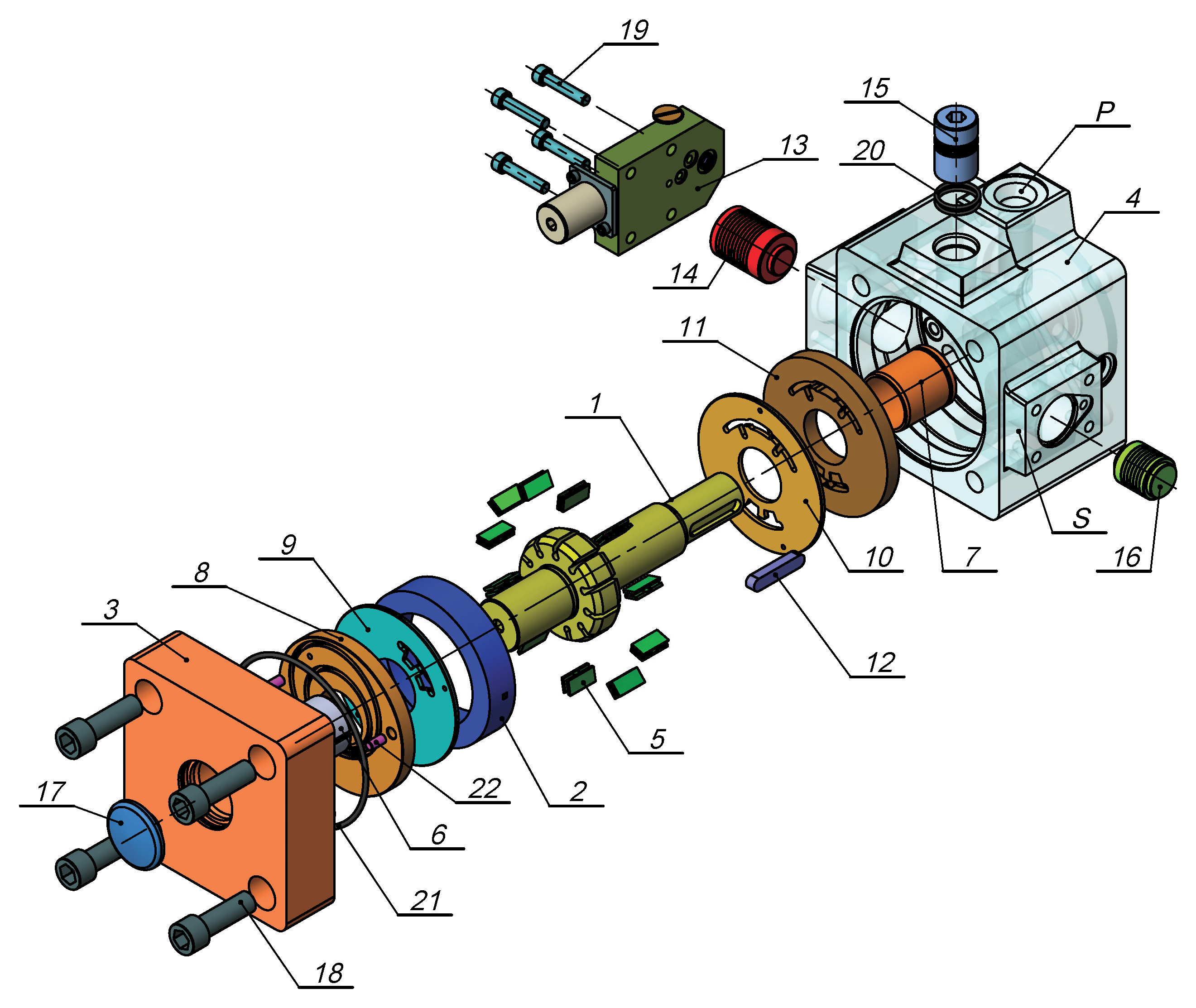
7 Type Horizontal triplex reciprocating singleacting piston pump Length stock(mm) 100 Diameter cylinder(mm) 80 Speed of pump (min -1 ) Displacement (LPM) Pressure (Mpa) Volume rate (%) 85 Total efficiency (%) 72 Motor power (Kw) 15 Triangle pulley wheel diameter (mm) B type; 5-slot; 410mm Input speed (r/min) 500 Maximum water absorption height (m) 2.5 Inlet pipe diameter (mm) 3 Discharge pipe diameter (mm) 2 Dimensions: length X width X height (mm) 1100X995X650 Weight (Kg) 500 Dimensions with motor(mm) 1600x995x650 Weight with motor(kg) 650
8 Model: BW-1500/12; Type: Four-cylinder single action piston pump; Cylinder Dia.:153mm; Stroke Length: 150mm; Power:185KW; Dimension: 1800*1400*1500mm; Weight: 2450Kg
9 Model: BW-1200/7; Type: Four-cylinder single action piston pump; Pump Speed: 70SPM; Stroke Length: 270mm; Liner; Liner; Power:185KW; Dimension: 3045*1440*2420mm; Weight(kg): 7200kg;
11 Type Horizontal Triplex Single Acting Piston Pump Gear Type Herringbone Gear Rated Input Power (KW/HP) 373/500 Gear Ratio 4.286:1 Rated Stroke (SPM) 165 Lubrication Forced & Splashing Stroke Length (mm/in) 190.5/7.5 Valve Cavity API-5# Inlet Connection 8 (203mm) Outlet Connection 4 Flange 5000psi Weight(Kg/Pound) 9770/21540 Rated Power Overall Dimension (L W H) mm Liner Dia. (in) and Pressure Rating (Mpa / psi) 6-3/4 6-1/ / /2 4 SPM HP KW Displacement (L/S)/(gpm) Based on 100% volumetric efficiency and 90% mechanical efficiency
12 A -Three interchangeable forged steel one piece cylinder. B -Threaded valve pot covers and cylinder heads. C -Valve pot according to API # 5 D -Discharge manifold C/W two 4"" PSI- API flanged outlets. E -Suction manifold C/W two flanged ends. F -Discharge pulsation dampener 5000 PSI W.P C/W all accessories. G -Lubrication: two kinds: one is inside gear pump driven by big gear wheel in the power end; the other is separate electric lubrication oil pump, which is driven separately by electric motor outside the power end. H -Pinion belt driven liner wash pump ASSY C/W all required accessories I -Relief valve (shear PIN type) PSI W.P. J -Pressure gauge PSI.
13 Type Horizontal Triplex Single Acting Piston Pump Gear Type Herringbone Gear Rated Input Power (KW/HP) 597/800 Gear Ratio 4.185:1 Rated Stroke (SPM) 150 Lubrication Forced & Splashing Stroke Length (mm/in) 228.6/9 Valve Cavity API-6# Inlet Connection 10 (254mm) Outlet Connection 5 1/8 Flange 5000PSI Weight(Kg/Pound) 14500/31970 SPM Rated Power HP KW Overall Dimension (L W H) mm Liner Dia.(in) and Pressure Rating (Mpa)/(psi) 6-3/4 6-1/2 6-1/ / / Displacement (L/S)/(gpm) Based on 100% volumetric efficiency and 90% mechanical efficiency
14 SPM Type Horizontal Triplex Single Acting Piston Gear Type Herringbone Gear Pump Rated Input Power (KW/HP) 746/1000 Gear Ratio 4.207:1 Rated Stroke (SPM) 140 Lubrication Forced & Splashing Stroke Length (mm/in) 254/10 Valve Cavity API-6# HP Inlet Connection 12 (305mm) Outlet Connection 5 1/8 Flange 5000PSI Weight(Kg/Pound) 18790/41425 Rated Power KW Overall Dimension (L W H) mm Liner Dia. (in) and Pressure Rating (Mpa / psi) 6-3/4 6-1/2 6-1/ / / Displacement (L/S)/(gpm) Based on 100% volumetric efficiency and 90% mechanical efficiency
15 A -Three interchangeable forged steel one piece fluid end. B -Threaded valve pot covers and cylinder heads. C -Valve pot according to API # 6 D -Discharge manifold C/W two 5 1/8"" PSI- API flanged outlets. E -Suction manifold C/W two flanged ends. F -Discharge pulsation dampener 5000 PSI W.P C/W all accessories. G -Lubrication system : oil circulating pump installation (electrical driven, Chinamade), with fresh water heat exchanger (oil cooling), Magnetic oil filter, Cartridge type gauge. H -Liner flushing system consisting of: One independent pump electrical driven by a 3HP electric motor. (China-made) I -Relief valve (JA-3 shear PIN type) PSI W.P to ac ng tank. J -Pressure gauge PSI.
16 Type Rated Input Power (KW/HP) SPM Horizontal Triplex Single Acting Piston Pump Gear Type Herringbone Gear 969/1300 Gear Ratio 4.206:1 Rated Stroke (SPM) 120 Lubrication Forced & Splashing Stroke Length (mm/in) 305/12 Valve Cavity API-7# Inlet Connection 12 (305mm) Outlet Connection 5 1/8 Flange 5000PSI Weight(Kg/Pound) 24572/54170 Rated Power HP KW Overall Dimension (L W H) Liner Dia.(in) and Pressure Rating (Mpa / psi) mm /4 6-1/ / Displacement (L/S)/(gpm) Based on 100% volumetric efficiency and 90% mechanical efficiency
17 Type Rated Input Power (KW/HP) Horizontal Triplex Single Acting Piston Pump Gear Type Herringbone Gear 1193/1600 Gear Ratio 4.206:1 Rated Stroke (SPM) 120 Lubrication Forced & Splashing Stroke Length(mm/in) 305/12 Valve Cavity API-7# SPM Inlet Connection 12 (305mm) Outlet Connection 5 1/8 Flange 5000PSI Weight(Kg/Pound) 24791/54660 Rated Power HP KW Overall Dimension (L W H) mm Liner Dia. (in) and Pressure Rating (Mpa / psi) 7 6-3/4 6-1/ / Displacement (L/S)/(gpm) Based on 100% volumetric efficiency and 90% mechanical efficiency
18 equipped with pistons and liners of 6 ¾ inch; Pulse dampener, KB-75 type, fully equipped with connection flange, gauge, nitrogen charging device, etc. JA-3 shear relief valve with key Discharge manifold, suction manifold and connections, etc. Greasing system, splashing & forced greasing; with the gear oil pump for greasing the gears, bearings, crosshead, guiding plates, and extension rod etc. Pinion belt driven liner wash pump ASSY C/W all required accessories (wash pump, belt guard, hoses, recirculation tank.) for cooling the liners pistons (there is electric spraying pump as alternative) Jib crane with hand hoist and trolley, to handle different weights Equipped with pump pressure gauges Technical documentation, including: - maintenance and operating manual; hydrostatic test report; report with pump parameters (flow, pressure, spm), obtained within the unit; materials test report; certificate of quality;
19 Model Type Power Rating Stroke Rating Stroke Length Gear Ratio F-2200 Triplex singleacting piston pump Dia. Of Suction Manifold 2200HP (1618KW) 105SPM 356mm Drive Wheel Rated Dia. Of Suction Liner Range Overall Size(mm) Speed (r/min) Manifold mm 130mm mm 6000*3465* Liner size (mm) and Pressure Rating(Mpa) Total Weight(Kg) Stroke per minute φ140 φ150 φ160 φ170 φ180 φ190 φ200 φ210 φ220 φ Displacement (L/S) Based on 100% volumetric efficiency and 90% mechanical efficiency
20 Type Horizontal three-cylinders singleacting piston pump Rated input power 185KW (251hp) Rated SPM 130 Stroke/min Rated displacement 2013L/min Stroke length 230mm Valve API 5# Suction diameter 8 Discharge diameter 3 Weight 3700kg Dimensions (LxWxH) 2320x1600x1760(mm) Liner (mm) SPM Rated MPa Rated Displacement (L/s) power kw kw kw kw Mechanical efficiency is 100%; volumetric efficiency 92%
21 We can offer unitized pump package according to customer different requirement: For pump power, you can choose either diesel engine (Caterpillar, Cummings, JDEC, or any other brand you like) or electric motor (AC or DC). For transmission system, you can choose mechanical (reducer +air clutch +V belt), hydraulic coupling or hydraulic torque converter. For supercharging system, you can choose either to install it or not. It can help to improve the suction effect.
23 Transmission Diesel drive: 1) Diesel Engine + Air Clutch + Gear Box+ Belt Pulley +V-belts +pump; 2)Diesel Engine + Cardan Shaft + hydraulic coupler + cardan shaft + pump; 3) Diesel Engine + hydraulic torque converter + cardan shaft + pump; 4) Diesel Engine + Reastar Gear Box + cardan shaft + pump; Transmission Electric Motor: 1) Belt Pulley + Belts; 2) Chain Wheels + Chain Box + Chains;


 8613371530291