
how a triplex mud pump works free sample

This website is using a security service to protect itself from online attacks. The action you just performed triggered the security solution. There are several actions that could trigger this block including submitting a certain word or phrase, a SQL command or malformed data.

Positive displacements pumps are generally used on drilling rigs to pump high pressure and high volume of drilling fluids throughout a drilling system. There are several reasons why the positive displacement mud pumps are used on the rigs.
The duplex pumps (Figure 1) have two cylinders with double acting. It means that pistons move back and take in drilling mud through open intake valve and other sides of the same pistons, the pistons push mud out through the discharge valves.
When the piston rod is moved forward, one of intake valves is lift to allow fluid to come in and one of the discharge valve is pushed up therefore the drilling mud is pumped out of the pump (Figure 2).
On the other hand, when the piston rod is moved backward drilling fluid is still pumped. The other intake and discharge valve will be opened (Figure 3).
The triplex pumps have three cylinders with single acting. The pistons are moved back and pull in drilling mud through open intake valves. When the pistons are moved forward and the drilling fluid is pushed out through open discharge valves.
When the piston rods are moved forward, the intake valves are in close position and the discharge valves are in open position allowing fluid to discharge (Figure 5).
On the contrary when the piston rods are moved backward, the intake valve are opened allowing drilling fluid coming into the pump (Figure 6). This video below shows how a triplex mud pump works.
Because each pump has power rating limit as 1600 hp, this will limit capability of pump. It means that you cannot pump at high rate and high pressure over what the pump can do. Use of a small liner will increase discharge pressure however the flow rate is reduces. Conversely, if a bigger liner is used to deliver more flow rate, maximum pump pressure will decrease.
As you can see, you can have 7500 psi with 4.5” liner but the maximum flow rate is only 297 GPM. If the biggest size of liner (7.25”) is used, the pump pressure is only 3200 psi.
Finally, we hope that this article would give you more understanding about the general idea of drilling mud pumps. Please feel free to add more comments.

Mud pump is one of the most critical equipment on the rig; therefore personnel on the rig must have good understanding about it. We’ve tried to find the good training about it but it is very difficult to find until we’ve seen this VDO training and it is a fantastic VDO training about the basic of mud pumps used in the oilfield. Total length of this VDO is about thirteen minutes and it is worth to watch it. You will learn about it so quickly. Additionally, we also add the full detailed transcripts which will acceleate the learning curve of learners.
Powerful mud pumps pick up mud from the suction tank and circulate the mud down hole, out the bit and back to the surface. Although rigs usually have two mud pumps and sometimes three or four, normally they use only one at a time. The others are mainly used as backup just in case one fails. Sometimes however the rig crew may compound the pumps, that is, they may use three or four pumps at the same time to move large volumes of mud when required.
Rigs use one of two types of mud pumps, Triplex pumps or Duplex pumps. Triplex pumps have three pistons that move back-and-forth in liners. Duplex pumps have two pistons move back and forth in liners.
Triplex pumps have many advantages they weight 30% less than a duplex of equal horsepower or kilowatts. The lighter weight parts are easier to handle and therefore easier to maintain. The other advantages include;
• One of the more important advantages of triplex over duplex pumps, is that they can move large volumes of mud at the higher pressure is required for modern deep hole drilling.
Triplex pumps are gradually phasing out duplex units. In a triplex pump, the pistons discharge mud only when they move forward in the liner. Then, when they moved back they draw in mud on the same side of the piston. Because of this, they are also called “single acting.” Single acting triplex pumps, pump mud at a relatively high speeds. Input horsepower ranges from 220 to 2200 or 164 to 1641 kW. Large pumps can pump over 1100 gallons per minute, over 4000 L per minute. Some big pumps have a maximum rated pressure of over 7000 psi over 50,000 kPa with 5 inch/127 mm liners.
Here is a schematic of a triplex pump. It has three pistons each moving in its own liner. It also has three intake valves and three discharge valves. It also has a pulsation dampener in the discharge line.
Look at the piston at left, it has just completed pushing mud out of the liner through the open discharge valve. The piston is at its maximum point of forward travel. The other two pistons are at other positions in their travel and are also pumping mud. But for now, concentrate on the left one to understand how the pump works. The left piston has completed its backstroke drawing in mud through the open intake valve. As the piston moved back it instead of the intake valve off its seat and drew mud in. A strong spring holds the discharge above closed. The left piston has moved forward pushing mud through the now open discharge valve. A strong spring holds the intake valve closed. They left piston has completed its forward stroke they form the length of the liner completely discharging the mud from it. All three pistons work together to keep a continuous flow of mud coming into and out of the pump.
Crewmembers can change the liners and pistons. Not only can they replace worn out ones, they can also install different sizes. Generally they use large liners and pistons when the pump needs to move large volumes of mud at relatively low pressure. They use a small liners and pistons when the pump needs to move smaller volumes of mud at a relatively high pressure.
In a duplex pump, pistons discharge mud on one side of the piston and at the same time, take in mud on the other side. Notice the top piston and the liner. As the piston moves forward, it discharges mud on one side as it draws in mud on the other then as it moves back, it discharges mud on the other side and draws in mud on the side it at had earlier discharge it. Duplex pumps are therefore double acting.
Double acting pumps move more mud on a single stroke than a triplex. However, because of they are double acting they have a seal around the piston rod. This seal keeps them from moving as fast as a triplex. Input horsepower ranges from 190 to 1790 hp or from 142 to 1335 kW. The largest pumps maximum rated working pressure is about 5000 psi, almost 35,000 kPa with 6 inch/152 mm linings.
A mud pump has a fluid end, our end and intake and the discharge valves. The fluid end of the pump contains the pistons with liners which take in or discharge the fluid or mud. The pump pistons draw in mud through the intake valves and push mud out through the discharge valves.
The power end houses the large crankshaft and gear assembly that moves the piston assemblies on the fluid end. Pumps are powered by a pump motor. Large modern diesel/electric rigs use powerful electric motors to drive the pump. Mechanical rigs use chain drives or power bands (belts) from the rig’s engines and compounds to drive the pump.
A pulsation dampener connected to the pump’s discharge line smooths out surges created by the pistons as they discharge mud. This is a standard bladder type dampener. The bladder and the dampener body, separates pressurized nitrogen gas above from mud below. The bladder is made from synthetic rubber and is flexible. When mud discharge pressure presses against the bottom of the bladder, nitrogen pressure above the bladder resists it. This resistance smoothes out the surges of mud leaving the pump.
Here is the latest type of pulsation dampener, it does not have a bladder. It is a sphere about 4 feet or 1.2 m in diameter. It is built into the mud pump’s discharge line. The large chamber is form of mud. It has no moving parts so it does not need maintenance. The mud in the large volume sphere, absorbs this surges of mud leaving the pump.
A suction dampener smooths out the flow of mud entering into the pump. Crewmembers mount it on the triplex mud pump’s suction line. Inside the steel chamber is a air charged rubber bladder or diaphragm. The crew charges of the bladder about 10 to 15 psi/50 to 100 kPa. The suction dampener absorbs surges in the mud pump’s suction line caused by the fast-moving pump pistons. The pistons, constantly starts and stops the mud’s flow through the pump. At the other end of the charging line a suction pumps sends a smooth flow of mud to the pump’s intake. When the smooth flow meets the surging flow, the impact is absorbed by the dampener.
Workers always install a discharge pressure relief valve. They install it on the pump’s discharge side in or near the discharge line. If for some reason too much pressure builds up in the discharge line, perhaps the drill bit or annulus gets plugged, the relief valve opens. That opened above protects the mud pump and system damage from over pressure.
Some rig owners install a suction line relief valve. They install it on top of the suction line near the suction dampener. They mount it on top so that it won’t clog up with mud when the system is shut down. A suction relief valve protects the charging pump and the suction line dampener. A suction relief valve usually has a 2 inch or 50 mm seat opening. The installer normally adjusts it to 70 psi or 500 kPa relieving pressure. If both the suction and the discharged valves failed on the same side of the pump, high back flow or a pressure surge would occur. The high backflow could damage the charging pump or the suction line dampener. The discharge line is a high-pressure line through which the pump moves mud. From the discharge line, the mud goes through the stand pipe and rotary hose to the drill string equipment.

The 2,200-hp mud pump for offshore applications is a single-acting reciprocating triplex mud pump designed for high fluid flow rates, even at low operating speeds, and with a long stroke design. These features reduce the number of load reversals in critical components and increase the life of fluid end parts.
The pump’s critical components are strategically placed to make maintenance and inspection far easier and safer. The two-piece, quick-release piston rod lets you remove the piston without disturbing the liner, minimizing downtime when you’re replacing fluid parts.
Choose a used Emsco FB-1600 Triplex Mud Pump from our inventory selection and save yourself some money on your next shallow drilling oilfield project. This Emsco FB-1600 Triplex Mud Pump is used and may show some minor wear.
We offer wholesale pricing on new Emsco FB-1600 Triplex Mud Pump and pass the savings on to you. Contact us to compare prices of different brands of Mud Pump. This equipment is brand new and has never been used.
Our large network often has surplus Emsco FB-1600 Triplex Mud Pump that go unused from a surplus purchase or a project that was not completed. Contact us to see what Emsco FB-1600 Triplex Mud Pump we have in inventory. The surplus Emsco FB-1600 Triplex Mud Pump are considered new but may have some weathering depending on where it was stored. Surplus oilfield equipment is usually stored at a yard or warehouse.
We have refurbished Mud Pumpthat have been used and brought up to functional standards. It is considered a ready to use, working Mud Pump. Please contact us for more information about our refurbished Emsco FB-1600 Triplex Mud Pump. These Mud Pump have been used and brought up to functional standards. It is considered a working Mud Pump. Please contact us for more information about the product.

Since the NOV A1700-PT Triplex Mud Pump was built approximately 60 years ago, the industry has widely accepted the three cylinder or triplex style pump. Triplex mud pumps are manufactured worldwide, and many companies have emulated the original design and developed an improved form of the triplex pump in the past decade.
NOV A1700-PT Triplex Mud Pumps have many advantages they weight 30% less than a duplex of equal horsepower or kilowatts. The lighter weight parts are easier to handle and therefore easier to maintain. The other advantages include;They cost less to operate
One of the more important advantages of triplex over duplex pumps, is that they can move large volumes of mud at the higher pressure is required for modern deep hole drilling.
NOV A1700-PT Triplex Mud Pump is gradually phasing out duplex units. In a triplex pump, the pistons discharge mud only when they move forward in the liner. Then, when they moved back they draw in mud on the same side of the piston. Because of this, they are also called “single acting.” Single acting triplex pumps, pump mud at a relatively high speeds. NOV A1700-PT Triplex Mud Pump has three pistons each moving in its own liner. It also has three intake valves and three discharge valves. It also has a pulsation dampener in the discharge line.
I’ve run into several instances of insufficient suction stabilization on rigs where a “standpipe” is installed off the suction manifold. The thought behind this design was to create a gas-over-fluid column for the reciprocating pump and eliminate cavitation.
When the standpipe is installed on the suction manifold’s deadhead side, there’s little opportunity to get fluid into all the cylinders to prevent cavitation. Also, the reciprocating pump and charge pump are not isolated.
The gas over fluid internal systems has limitations too. The standpipe loses compression due to gas being consumed by the drilling fluid. In the absence of gas, the standpipe becomes virtually defunct because gravity (14.7 psi) is the only force driving the cylinders’ fluid. Also, gas is rarely replenished or charged in the standpipe.
Installing a suction stabilizer from the suction manifold port supports the manifold’s capacity to pull adequate fluid and eliminates the chance of manifold fluid deficiency, which ultimately prevents cavitation.
Another benefit of installing a suction stabilizer is eliminating the negative energies in fluids caused by the water hammer effect from valves quickly closing and opening.
The suction stabilizer’s compressible feature is designed to absorb the negative energies and promote smooth fluid flow. As a result, pump isolation is achieved between the charge pump and the reciprocating pump.
The isolation eliminates pump chatter, and because the reciprocating pump’s negative energies never reach the charge pump, the pump’s expendable life is extended.
Investing in suction stabilizers will ensure your pumps operate consistently and efficiently. They can also prevent most challenges related to pressure surges or pulsations in the most difficult piping environments.
Sigma Drilling Technologies’ Charge Free Suction Stabilizer is recommended for installation. If rigs have gas-charged cartridges installed in the suction stabilizers on the rig, another suggested upgrade is the Charge Free Conversion Kits.

OK, all y’all air drillers just thumb on over to Porky’s column or something. This is for mud drillers. On second thought, I know a lot of you air guys drill about three mud wells a year, and consider it a hassle to rig up mud. So, maybe something I say will be interesting …
The mud pump is the heart of the circulating system, and mud is the blood circulating in the hole. I’ve talked about mud before and will again, but this month, let’s talk about the pump.
Historically, more wells, of every kind, have been drilled with duplex pumps than any other kind. They are simple and strong, and were designed in the days when things were meant to last. Most water well drillers use them. The drawbacks are size and weight. A pump big enough to do the job might be too big to fit on the rig, so some guys use skid-mounted pumps. They also take a fair amount of horsepower. If you were to break down the horsepower requirements of your rig, you would find out that the pump takes more power than the rotary and hoist combined. This is not a bad thing, since it does a lot of the work drilling. While duplex pumps generally make plenty of volume, one of the limiting factors is pressure. Handling the high pressures demanded by today’s oil well drilling required a pump so big and heavy as to be impractical. Some pretty smart guys came up with the triplex pump. It will pump the same — or more — volume in a smaller package, is easy to work on and will make insane pressure when needed. Some of the modern frack outfits run pumps that will pump all day long at 15,000 psi. Scary. Talk about burning some diesel.
The places that triplex pumps have in the shallow drilling market are in coring and air drilling. The volume needs are not as great. For instance, in hard rock coring, surface returns are not always even seen, and the fluid just keeps the diamonds cool. In air drilling, a small triplex is used to inject foam or other chemicals into the air line. It’s basically a glorified car wash pump. The generic name is Bean pump, but I think this just justifies a higher price. Kinda like getting the same burger at McDonald’s versus in a casino.
One of the reasons water well drillers don’t run triplex pumps, besides not needing insane pressure, is they require a positive suction head. In other words, they will not pick up out of the pit like a duplex. They require a centrifugal charging pump to feed them, and that is just another piece of equipment to haul and maintain.
This brings me to another thought: charging. I know a lot of drillers running duplex pumps that want to improve the efficiency of their pumps. Duplexes with a negative suction head generally run at about 85 percent efficiency. The easy way to improve the efficiency is to charge them, thus assuring a 100 percent efficiency. This works great, but almost every one of them, after doing all that work and rigging up a charging pump, tells me that their pump output doubled. Being the quiet, mild mannered type that I am, I don’t say “Bull,” but it is. A duplex pump is a positive displacement pump. That means that it can deliver no more than the displacement it was designed for. You can only fill the cylinder up until it is full. It won’t take any more. The one exception to this is when you are pumping at very low pressure. Then the charging pump will over run the duplex, float the valves and produce a lot more fluid. Might as well shut off the duplex and drill with the charging pump.
Another common pump used in the water well industry is the centrifugal. You see them mostly on air rigs that don’t use mud too often. They have their place, but are a different breed of cat. They are not positive displacement. Flow is a function of speed and horsepower up to the limits of the pump. After that, they just dead-head. With large diameter drill pipe they make a lot of mud, but after the hole gets deeper, friction losses — both inside and outside the drill pipe — build up. This means that the deeper you go, the less circulation you have. This slows the whole process. Positive displacement pumps don’t do this; they pump the same per stroke regardless of pressure. It just takes more horsepower. Also, displacement calculations like bottoms-up time and cement placement are just about impossible. One way to get around the limited pressure of centrifugal pumps is to run two of them in series. I’ve seen a few of these rig-ups and they work very well for large diameter drilling. They will make almost the same pressure as a big duplex for a lot less money. They are still variable displacement, but they roll so much fluid that it doesn’t seem to matter. And run at pretty reasonable depths, too: 300 to 400 psi at 400 gpm is not uncommon with two 3 x 4 centrifugal pumps in series.
I reckon there are pumps for every type of drilling. It is just a matter of using the right one correctly. I once drilled a 42-inch hole 842 feet deep with a 5½ x 8 duplex. Talk about long bottoms-up time … but we got the casing in with less than two feet of fill on bottom! Took time, but we got-er-done.
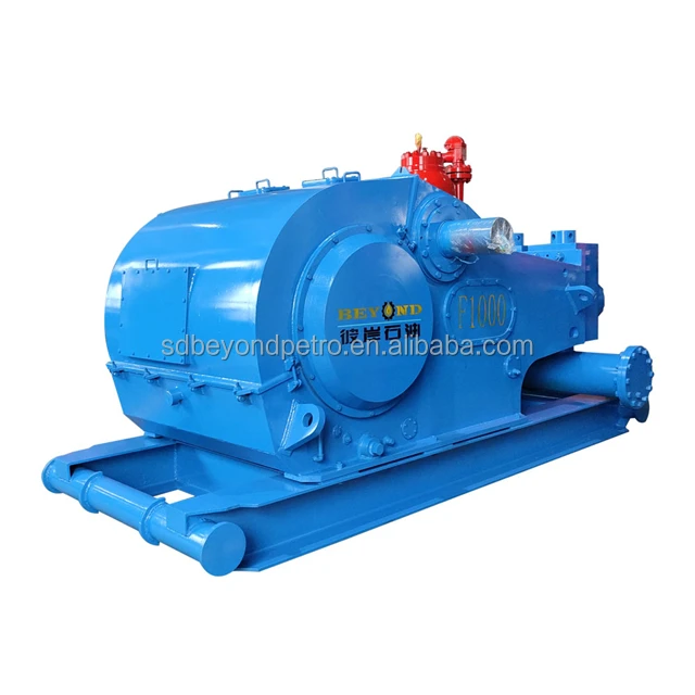
A mud pump (sometimes referred to as a mud drilling pump or drilling mud pump), is a reciprocating piston/plunger pump designed to circulate drilling fluid under high pressure (up to 7,500 psi or 52,000 kPa) down the drill string and back up the annulus. A mud pump is an important part of the equipment used for oil well drilling.
Mud pumps can be divided into single-acting pump and double-acting pump according to the completion times of the suction and drainage acting in one cycle of the piston"s reciprocating motion.
Mud pumps come in a variety of sizes and configurations but for the typical petroleum drilling rig, the triplex (three piston/plunger) mud pump is used. Duplex mud pumps (two piston/plungers) have generally been replaced by the triplex pump, but are still common in developing countries. Two later developments are the hex pump with six vertical pistons/plungers, and various quintuplexes with five horizontal piston/plungers. The advantages that these new pumps have over convention triplex pumps is a lower mud noise which assists with better measurement while drilling (MWD) and logging while drilling (LWD) decoding.
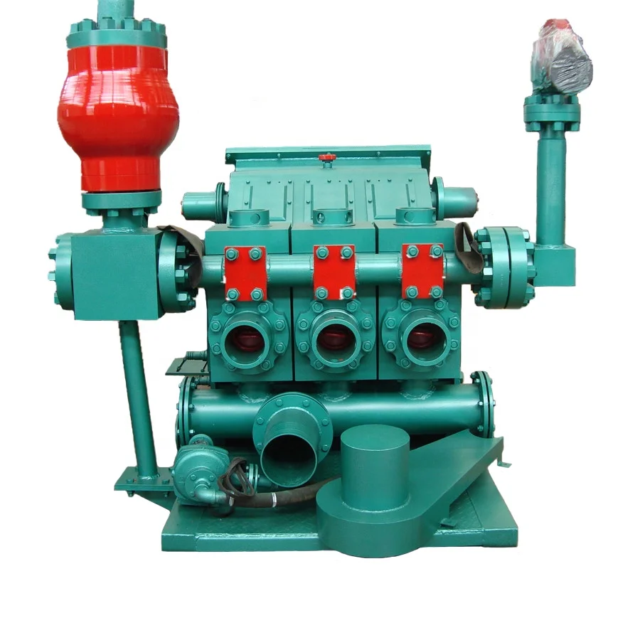
The fluid end produces the pumping process with valves, pistons, and liners. Because these components are high-wear items, modern pumps are designed to allow quick replacement of these parts.
To reduce severe vibration caused by the pumping process, these pumps incorporate both a suction and discharge pulsation dampener. These are connected to the inlet and outlet of the fluid end.
The power end converts the rotation of the drive shaft to the reciprocating motion of the pistons. In most cases a crosshead crank gear is used for this.
Displacement is calculated as discharged liters per minute. It is related to the drilling hole diameter and the return speed of drilling fluid from the bottom of the hole, i.e. the larger the diameter of drilling hole, the larger the desired displacement. The return speed of drilling fluid should wash away the debris and rock powder cut by the drill from the bottom of the hole in a timely manner, and reliably carry them to the earth"s surface. When drilling geological core, the speed is generally in range of 0.4 to 1.0 m^3/min.
The pressure of the pump depends on the depth of the drilling hole, the resistance of flushing fluid (drilling fluid) through the channel, as well as the nature of the conveying drilling fluid. The deeper the drilling hole and the greater the pipeline resistance, the higher the pressure needed.
With the changes of drilling hole diameter and depth, the displacement of the pump can be adjusted accordingly. In the mud pump mechanism, the gearbox or hydraulic motor is equipped to adjust its speed and displacement. In order to accurately measure the changes in pressure and displacement, a flow meter and pressure gauge are installed in the mud pump.
The construction department should have a special maintenance worker that is responsible for the maintenance and repair of the machine. Mud pumps and other mechanical equipment should be inspected and maintained on a scheduled and timely basis to find and address problems ahead of time, in order to avoid unscheduled shutdown. The worker should attend to the size of the sediment particles; if large particles are found, the mud pump parts should be checked frequently for wear, to see if they need to be repaired or replaced. The wearing parts for mud pumps include pump casing, bearings, impeller, piston, liner, etc. Advanced anti-wear measures should be adopted to increase the service life of the wearing parts, which can reduce the investment cost of the project, and improve production efficiency. At the same time, wearing parts and other mud pump parts should be repaired rather than replaced when possible.

This website is using a security service to protect itself from online attacks. The action you just performed triggered the security solution. There are several actions that could trigger this block including submitting a certain word or phrase, a SQL command or malformed data.
My first days as an MWD field tech I heard horror stories surrounding what is commonly referred to as “pump noise”. I quickly identified the importance of learning to properly identify this “noise”. From the way it was explained to me, this skill might prevent the company you work from losing a job with an exploration company, satisfy your supervisor or even allow you to become regarded as hero within your organization if you’ve proven yourself handy at this skill.
“Pump noise” is a reference to an instability in surface pressure created by the mud pumps on a modern drilling rig, often conflated with any pressure fluctuation at a similar frequency to pulses generated by a mud pulser, but caused by a source external to the mud pulser. This change in pressure is what stands in the way of the decoder properly understanding what the MWD tool is trying to communicate. For the better part of the first year of learning my role I wrongly assumed that all “noise” would be something audible to the human ear, but this is rarely the case.
In an ideal drilling environment surface pressure will remain steady and all pressure increases, and decreases will be gradual. This way, when the pulser valve closes(pulses), it’s easily detectable on surface by computers. Unfortunately drilling environments are rarely perfect and there are many things that can emulate a pulse thus causing poor or inaccurate data delivery to surface. The unfortunate circumstance of this means drilling operations must come to halt until data can once again be decoded on surface. This pause in the drilling process is commonly referred to at NPT or non-productive time. For those of you unfamiliar these concepts, I’ll explain some of the basics.
A mud pulser is a valve that briefly inhibits flow of drilling fluid traveling through the drill string, creating a sharp rise and fall of pressure seen on surface, also known as a “pulse”.
Depending on if the drilling fluid is being circulated in closed or open loop, it will be drawn from a tank or a plastic lined reservoir by a series(or one) mud pumps and channeled into the stand pipe, which runs up the derrick to the Kelly-hose, through the saver sub and down the drill-pipe(drill-string). Through the filter screen past an agitator or exciter, around the MWD tool, through a mud motor and out of the nozzles in the bit. At this point the fluid begins it’s journey back to the drilling rig through the annulus, past the BOP then out of the flow line and either over the shale shakers and/or back in the fluid reservoir.
Developing a firm grasp on these fundamentals were instrumental in my success as a field technician and an effective troubleshooter. As you can tell, there are a lot of components involved in this conduit which a mud pulser telemeters through. The way in which many of these components interact with the drilling fluid can suddenly change in ways that slightly create sharp changes in pressure, often referred to as “noise”. This “noise” creates difficulty for the decoder by suddenly reducing or increasing pressure in a manner that the decoder interprets a pulse. To isolate these issues, you must first acknowledge potential of their existence. I will give few examples of some of these instances below:
Suction screens on intake hoses will occasionally be too large, fail or become unfastened thus allowing large debris in the mud system. Depending on the size of debris and a little bit of luck it can end up in an area that will inhibit flow, circumstantially resulting in a sudden fluctuation of pressure.
Any solid form of drilling fluid additive, if improperly or inconsistently mixed, can restrict the flow path of the fluid resulting in pressure increase. Most notably this can happen at the pulser valve itself, but it is not the only possible outcome. Several other parts of this system can be affected as well. LCM or loss of circulation material is by far the most common additive, but the least overlooked. It’s important for an MWD technician to be aware of what’s being added into the drilling fluid regardless if LCM isn’t present. Through the years I have seen serval other improperly mixed additives cause a litany of pressure related issues.
This specifically is a term used to refer to the mud motor stator rubber deterioration, tearing into small pieces and passing through the nozzles of the bit. Brief spikes in pressure as chunks of rubber pass through one or more nozzles of the bit can often be wrongly interpreted as pulses.
Sometimes when mud is displaced or a pump suction isn’t completely submerged, tiny air bubbles are introduced into the drilling fluid. Being that air compresses and fluid does not, pulses can be significantly diminished and sometimes non-existent.
Formation cuttings staying downhole can cause what is known as a pack-off of the anulus, which typically cause slower trends in pressure. A pack-off is less likely to cause significant decoding issues, but can.
Failed surface equipment such as transducers and transducer cables can occasionally allow current external to the circuit into the signal wire, resulting in what appears to be a pressure increase on the decoder. When experiencing poor decoding these are some of the first pieces of equipment to be replaced.
As many of you know the downhole mud motor is what enables most drilling rigs to steer a well to a targeted location. The motor generates bit RPM by converting fluid velocity to rotor/bit RPM, otherwise known as hydraulic horsepower. Anything downhole that interacts with the bit will inevitably affect surface pressure. One of the most common is bit weight. As bit weight is increased, so does surface pressure. It’s important to note that consistent weight tends to be helpful to the decoder by increasing the amplitude of pulses, but inconsistent bit weight, depending on frequency of change, can negatively affect decoding. Bit bounce, bit bite and inconsistent weight transfer can all cause pressure oscillation resulting in poor decoding. Improper bit speed or bit type relative to a given formation are other examples of possible culprits as well.
Over time mud pump components wear to the point failure. Pump pistons(swabs), liners, valves and valve seats are all necessary components for generating stable pressure. These are the moving parts on the fluid side of the pump and the most frequent point of failure. Another possible culprit but less common is an inadequately charged pulsation dampener. Deteriorating rubber hoses anywhere in the fluid path, from the mud pump to the saver sub, such as a kelly-hose, can cause an occasional pressure oscillation.
If I could change one thing about today’s directional drilling industry, it would be eliminating the term “pump noise”. The misleading term alone has caused confusion for countless people working on a drilling rig. On the other hand, I’m happy to have learned these lessons the hard way because they seem engrained into my memory. As technology improves, so does the opportunities for MWD technology companies to provide useful solutions. Solutions to aid MWD service providers to properly isolate or overcome the challenges that lead to decoding issues. As an industry we have come a lot further from when I had started, but there is much left to be desired. I’m happy I can use my experiences by contributing to an organization capable of acknowledging and overcoming these obstacles through the development of new technology.

Legal status (The legal status is an assumption and is not a legal conclusion. Google has not performed a legal analysis and makes no representation as to the accuracy of the status listed.)
Current Assignee (The listed assignees may be inaccurate. Google has not performed a legal analysis and makes no representation or warranty as to the accuracy of the list.)
Priority date (The priority date is an assumption and is not a legal conclusion. Google has not performed a legal analysis and makes no representation as to the accuracy of the date listed.)
Assignors: HIGH PRESSURE INTEGRITY INC., PRECISION ENERGY SERVICES INC., PRECISION ENERGY SERVICES ULC, WEATHERFORD CANADA LTD., WEATHERFORD NETHERLANDS B.V., WEATHERFORD NORGE AS, WEATHERFORD SWITZERLAND TRADING AND DEVELOPMENT GMBH, WEATHERFORD TECHNOLOGY HOLDINGS LLC, WEATHERFORD U.K. LIMITED
Assignors: HIGH PRESSURE INTEGRITY, INC., PRECISION ENERGY SERVICES ULC, PRECISION ENERGY SERVICES, INC., WEATHERFORD CANADA LTD., WEATHERFORD NETHERLANDS B.V., WEATHERFORD NORGE AS, WEATHERFORD SWITZERLAND TRADING AND DEVELOPMENT GMBH, WEATHERFORD TECHNOLOGY HOLDINGS, LLC, WEATHERFORD U.K. LIMITED
Assignors: HIGH PRESSURE INTEGRITY, INC., PRECISION ENERGY SERVICES ULC, PRECISION ENERGY SERVICES, INC., WEATHERFORD CANADA LTD., WEATHERFORD NETHERLANDS B.V., WEATHERFORD NORGE AS, WEATHERFORD SWITZERLAND TRADING AND DEVELOPMENT GMBH, WEATHERFORD TECHNOLOGY HOLDINGS, LLC, WEATHERFORD U.K. LIMITED
Assigned to HIGH PRESSURE INTEGRITY, INC., WEATHERFORD SWITZERLAND TRADING AND DEVELOPMENT GMBH, WEATHERFORD NETHERLANDS B.V., WEATHERFORD TECHNOLOGY HOLDINGS, LLC, WEATHERFORD U.K. LIMITED, PRECISION ENERGY SERVICES, INC., PRECISION ENERGY SERVICES ULC, WEATHERFORD CANADA LTD., WEATHERFORD NORGE AS
Assigned to WEATHERFORD U.K. LIMITED, WEATHERFORD NORGE AS, HIGH PRESSURE INTEGRITY, INC., PRECISION ENERGY SERVICES, INC., WEATHERFORD SWITZERLAND TRADING AND DEVELOPMENT GMBH, PRECISION ENERGY SERVICES ULC, WEATHERFORD TECHNOLOGY HOLDINGS, LLC, WEATHERFORD CANADA LTD, WEATHERFORD NETHERLANDS B.V.
Assignors: HIGH PRESSURE INTEGRITY, INC., PRECISION ENERGY SERVICES, INC., WEATHERFORD CANADA LTD., WEATHERFORD NETHERLANDS B.V., WEATHERFORD NORGE AS, WEATHERFORD SWITZERLAND TRADING AND DEVELOPMENT GMBH, WEATHERFORD TECHNOLOGY HOLDINGS, LLC, WEATHERFORD U.K. LIMITED
F04B15/02—Pumps adapted to handle specific fluids, e.g. by selection of specific materials for pumps or pump parts the fluids being viscous or non-homogeneous
A quintuplex mud pump has a crankshaft supported in the pump by external main bearings. The crankshaft has five eccentric sheaves, two internal main bearing sheaves, and two bull gears. Each of the main bearing sheaves supports the crankshaft by a main bearing. One main bearing sheave is disposed between second and third eccentric sheaves, while the other main bearing sheave is disposed between third and fourth eccentric sheaves. One bull gear is disposed between the first and second eccentric sheaves, while the second bull gear is disposed between fourth and fifth eccentric sheaves. A pinion shaft has pinion gears interfacing with the crankshaft"s bull gears. Connecting rods on the eccentric sheaves use roller bearings and transfer rotational movement of the crankshaft to pistons of the pump"s fluid assembly.
This is a non-provisional of U.S. Provisional Appl. Ser. No. 60/977,956, filed 5, Oct. 2007, which is incorporated herein by reference and to which priority is claimed.
Triplex mud pumps pump drilling mud during well operations. An example of a typical triplex mud pump 10 shown in FIG. 1A has a power assembly 12, a crosshead assembly 14, and a fluid assembly 16. Electric motors (not shown) connect to a pinion shaft 30 that drives the power assembly 12. The crosshead assembly 14 converts the rotational movement of the power assembly 12 into reciprocating movement to actuate internal pistons or plungers of the fluid assembly 16. Being triplex, the pump"s fluid assembly 16 has three internal pistons to pump the mud.
As shown in FIG. 1B, the pump"s power assembly 14 has a crankshaft 20 supported at its ends by double roller bearings 22. Positioned along its intermediate extent, the crankshaft 20 has three eccentric sheaves 24-1 . . . 24-3, and three connecting rods 40 mount onto these sheaves 24 with cylindrical roller bearings 26. These connecting rods 40 connect by extension rods (not shown) and the crosshead assembly (14) to the pistons of the pump"s fluid assembly 16.
In addition to the sheaves, the crankshaft 20 also has a bull gear 28 positioned between the second and third sheaves 24-2 and 24-3. The bull gear 28 interfaces with the pinion shaft (30) and drives the crankshaft 20"s rotation. As shown particularly in FIG. 1C, the pinion shaft 30 also mounts in the power assembly 14 with roller bearings 32 supporting its ends. When electric motors couple to the pinion shaft"s ends 34 and rotate the pinion shaft 30, a pinion gear 38 interfacing with the crankshaft"s bull gear 28 drives the crankshaft (20), thereby operating the pistons of the pump"s fluid assembly 16.
When used to pump mud, the triplex mud pump 10 produces flow that varies by approximately 23%. For example, the pump 10 produces a maximum flow level of about 106% during certain crankshaft angles and produces a minimum flow level of 83% during other crankshaft angles, resulting in a total flow variation of 23% as the pump"s pistons are moved in differing exhaust strokes during the crankshaft"s rotation. Because the total flow varies, the pump 10 tends to produce undesirable pressure changes or “noise” in the pumped mud. In turn, this noise interferes with downhole telemetry and other techniques used during measurement-while-drilling (MWD) and logging-while-drilling (LWD) operations.
In contrast to mud pumps, well-service pumps (WSP) are also used during well operations. A well service pump is used to pump fluid at higher pressures than those used to pump mud. Therefore, the well service pumps are typically used to pump high pressure fluid into a well during frac operations or the like. An example of a well-service pump 50 is shown in FIG. 2. Here, the well service pump 50 is a quintuplex well service pump, although triplex well service pumps are also used. The pump 50 has a power assembly 52, a crosshead assembly 54, and a fluid assembly 56. A gear reducer 53 on one side of the pump 50 connects a drive (not shown) to the power assembly 52 to drive the pump 50.
As shown in FIG. 3, the pump"s power assembly 52 has a crankshaft 60 with five crankpins 62 and an internal main bearing sheave 64. The crankpins 62 are offset from the crankshaft 60"s axis of rotation and convert the rotation of the crankshaft 60 in to a reciprocating motion for operating pistons (not shown) in the pump"s fluid assembly 56. Double roller bearings 66 support the crankshaft 60 at both ends of the power assembly 52, and an internal double roller bearing 68 supports the crankshaft 60 at its main bearing sheave 64. One end 61 of the crankshaft 60 extends outside the power assembly 52 for coupling to the gear reducer (53; FIG. 2) and other drive components.
As shown in FIG. 4A, connecting rods 70 connect from the crankpins 62 to pistons or plungers 80 via the crosshead assembly 54. FIG. 4B shows a typical connection of a connecting rod 70 to a crankpin 62 in the well service pump 50. As shown, a bearing cap 74 fits on one side of the crankpin 62 and couples to the profiled end of the connecting rod 70. To reduce friction, the connection uses a sleeve bearing 76 between the rod 70, bearing cap 74, and crankpin 62. From the crankpin 62, the connecting rod 70 connects to a crosshead 55 using a wrist pin 72 as shown in FIG. 4A. The wrist pin 72 allows the connecting rod 70 to pivot with respect to the crosshead 55, which in turn is connected to the plunger 80.
In use, an electric motor or an internal combustion engine (such as a diesel engine) drives the pump 50 by the gear reducer 53. As the crankshaft 60 turns, the crankpins 62 reciprocate the connecting rods 70. Moved by the rods 70, the crossheads 55 reciprocate inside fixed cylinders. In turn, the plunger 80 coupled to the crosshead 55 also reciprocates between suction and power strokes in the fluid assembly 56. Withdrawal of a plunger 80 during a suction stroke pulls fluid into the assembly 56 through the input valve 82 connected to an inlet hose or pipe (not shown). Subsequently pushed during the power stroke, the plunger 80 then forces the fluid under pressure out through the output valve 84 connected to an outlet hose or pipe (not shown).
In contrast to using a crankshaft for a quintuplex well-service pump that has crankpins 62 as discussed above, another type of quintuplex well-service pump uses eccentric sheaves on a direct drive crankshaft. FIG. 4C is an isolated view of such a crankshaft 90 having eccentric sheaves 92-1 . . . 92-5 for use in a quintuplex well-service pump. External main bearings (not shown) support the crankshaft 90 at its ends 96 in the well-service pumps housing (not shown). To drive the crankshaft 90, one end 91 extends beyond the pumps housing for coupling to drive components, such as a gear box. The crankshaft 90 has five eccentric sheaves 92-1 . . . 92-5 for coupling to connecting rods (not shown) with roller bearings. The crankshaft 90 also has two internal main bearing sheaves 94-1, 94-2 for internal main bearings used to support the crankshaft 90 in the pump"s housing.
In the past, quintuplex well-service pumps used for pumping frac fluid or the like have been substituted for mud pumps during drilling operations to pump mud. Unfortunately, the well-service pump has a shorter service life compared to the conventional triplex mud pumps, making use of the well-service pump as a mud pump less desirable in most situations. In addition, a quintuplex well-service pump produces a great deal of white noise that interferes with MWD and LWD operations, further making the pump"s use to pump mud less desirable in most situations. Furthermore, the well-service pump is configured for direct drive by a motor and gear box directly coupling on one end of the crankshaft. This direct coupling limits what drives can be used with the pump. Moreover, the direct drive to the crankshaft can produce various issues with noise, balance, wear, and other associated problems that make use of the well-service pump to pump mud less desirable.
One might expect to provide a quintuplex mud pump by extending the conventional arrangement of a triplex mud pump (e.g., as shown in FIG. 1B) to include components for two additional pistons or plungers. However, the actual design for a quintuplex mud pump is not as easy as extending the conventional arrangement, especially in light of the requirements for a mud pump"s operation such as service life, noise levels, crankshaft deflection, balance, and other considerations. As a result, acceptable implementation of a quintuplex mud pump has not been achieved in the art during the long history of mud pump design.
What is needed is an efficient mud pump that has a long service life and that produces low levels of white noise during operation so as not to interfere with MWD and LWD operations while pumping mud in a well.
A quintuplex mud pump is a continuous duty, reciprocating plunger/piston pump. The mud pump has a crankshaft supported in the pump by external main bearings and uses internal gearing and a pinion shaft to drive the crankshaft. Five eccentric sheaves and two internal main bearing sheaves are provided on the crankshaft. Each of the main bearing sheaves supports the intermediate extent of crankshaft using bearings. One main bearing sheave is disposed between the second and third eccentric sheaves, while the other main bearing sheave is disposed between the third and fourth eccentric sheaves.
One or more bull gears are also provided on the crankshaft, and the pump"s pinion shaft has one or more pinion gears that interface with the one or more bull gears. If one bull gear is used, the interface between the bull and pinion gears can use herringbone or double helical gearing of opposite hand to avoid axial thrust. If two bull gears are used, the interface between the bull and pinion gears can use helical gearing with each having opposite hand to avoid axial thrust. For example, one of two bull gears can be disposed between the first and second eccentric sheaves, while the second bull gear can be disposed between fourth and fifth eccentric sheaves. These bull gears can have opposite hand. The pump"s internal gearing allows the pump to be driven conventionally and packaged in any standard mud pump packaging arrangement. Electric motors (for example, twin motors made by GE) may be used to drive the pump, although the pump"s rated input horsepower may be a factor used to determine the type of motor.
Connecting rods connect to the eccentric sheaves and use roller bearings. During rotation of the crankshaft, these connecting rods transfer the crankshaft"s rotational movement to reciprocating motion of the pistons or plungers in the pump"s fluid assembly. As such, the quintuplex mud pump uses all roller bearings to support its crankshaft and to transfer crankshaft motion to the connecting rods. In this way, the quintuplex mud pump can reduce the white noise typically produced by conventional triplex mud pumps and well service pumps that can interfere with MWD and LWD operations.
Turning to the drawings, a quintuplex mud pump 100 shown in FIGS. 5 and 6A-6B has a power assembly 110, a crosshead assembly 150, and a fluid assembly 170. Twin drives (e.g., electric motors, etc.) couple to ends of the power assembly"s pinion shaft 130 to drive the pump"s power assembly 110. As shown in FIGS. 6A-6B, internal gearing within the power assembly 110 converts the rotation of the pinion shaft 130 to rotation of a crankshaft 120. The gearing uses pinion gears 138 on the pinion shaft 130 that couple to bull gears 128 on the crankshaft 120 and transfer rotation of the pinion shaft 130 to the crankshaft 120.
For support, the crankshaft 120 has external main bearings 122 supporting its ends and two internal main bearings 127 supporting its intermediate extent in the assembly 110. As best shown in FIG. 6A, rotation of the crankshaft 120 reciprocates five independent connecting rods 140. Each of the connecting rods 140 couples to a crosshead 160 of the crosshead assembly 150. In turn, each of the crossheads 160 converts the connecting rod 40"s movement into a reciprocating movement of an intermediate pony rod 166. As it reciprocates, the pony rod 166 drives a coupled piston or plunger (not shown) in the fluid assembly 170 that pumps mud from an intake manifold 192 to an output manifold 198. Being quintuplex, the mud pump 100 has five such pistons movable in the fluid assembly 170 for pumping the mud.
Shown in isolated detail in FIG. 7, the crankshaft 120 has five eccentric sheaves 124-1 through 124-5 disposed thereon. Each of these sheaves can mechanically assemble onto the main vertical extent of the crankshaft 120 as opposed to being welded thereon. During rotation of the crankshaft 120, the eccentric sheaves actuate in a firing order of 124-1, 3, 5, 2 and 4 to operate the fluid assembly"s pistons (not shown). This order allows the crankshaft 120 to be assembled by permitting the various sheaves to be mounted thereon. Preferably, each of the eccentric sheaves 124-1 . . . 124-5 is equidistantly spaced on the crankshaft 120 for balance.
The crankshaft 120 also has two internal main bearing sheaves 125-1 and 125-2 positioned respectively between the second and third sheaves 124-2 and 124-3 and the third and fourth sheaves 124-3 and 124-4. In the present embodiment, the crankshaft 120 also has two bull gear supports 128-1 and 128-2 disposed thereon, although one bull gear may be used by itself in other embodiments. The first bull gear support 128-1 is positioned between the first and second eccentric sheaves 124-1 and 124-2, and the second of the bull gear support 128-2 is positioned between the fourth and fifth eccentric sheaves 124-4 and 124-5.
Preferably, each of the sheaves 124-1 . . . 124-5, bull gear supports 128-1 & 128-2, and bearing sheaves 125-1 & 125-2 are equidistantly spaced on the crankshaft 120 for balance. In one implementation for the crankshaft 120 having a length a little greater than 90-in. (e.g., 90.750-in.), each of the sheaves 124, 125 and supports 128 are equidistantly spaced from one another by 9-inches between their rotational centers. The end sheaves 124-1 and 124-5 can be positioned a little over 9-in. (e.g., 9.375-in.) from the ends of the crankshaft 120.
The additional detail of FIG. 8 shows the crankshaft 120 supported in the power assembly 110 and having the connecting rods 140 mounted thereon. As noted above, double roller bearings 122 support the ends of the crankshaft 120 in the assembly 110. Internally, main bearings 123 support the intermediate extent of the crankshaft 120 in the assembly 110. In particular, the main bearings 126 position on the main bearing sheaves 125-1 and 125-2 and are supported by carriers 125 mounted to the assembly 110 at 129. The external main bearings 122 are preferably spherical bearings to better support radial and axial loads. The internal main bearings 125 preferably use cylindrical bearings.
Five connector rods 140 use roller bearings 126 to fit on the eccentric sheaves 124-1 . . . 124-5. Each of the roller bearings 126 preferably uses cylindrical bearings. The rods 140 extend from the sheaves 124-1 . . . 124-5 (perpendicular to the figure) and couple the motion of the crankshaft 120 to the fluid assembly (170) via crossheads (160) as is discussed in more detail below with reference to FIGS. 10A-10B.
As shown in FIG. 9, the pinion shaft 130 mounts with roller bearings 132 in the power assembly 110 with its free ends 134 extending on both sides of the assembly 110 for coupling to drive components (not shown). As noted previously, the pinion gears 138 on the shaft 130 interface with the bull gears 128 on the crankshaft (120). Preferably, the interface uses helical gearing of opposite hand. In particular, the two pinion gears 138 on the pinion shaft 130 have helical teeth that have an opposite orientation or hand relative to one another. These helical teeth couple in parallel fashion to oppositely oriented helical teeth on the complementary bull gears 128 on the crankshaft 120. (The opposing orientation of helical teeth on the bull gears 128 and pinion gears 138 can best be seen in FIGS. 6A-6B). The helical gearing transfers rotation of the pinion shaft 130 to the crankshaft 120 in a balanced manner. In an alternative embodiment, the pinion shaft 130 can have one pinion gear 138, and the crankshaft 120 can have one bull gear 128. Preferably, these single gears 138/128 use herringbone or double helical gearing of opposite hand to avoid imparting axial thrust to the crankshaft 120.
The cross-section in FIG. 10A shows a crosshead 160 for the quintuplex mud pump. The end of the connecting rod 140 couples by a wrist pin 142 and bearing 144 to a crosshead body 162 that is movable in a crosshead guide 164. A pony rod 166 coupled to the crosshead body 162 extends through a stuffing box gasket 168 on a diaphragm plate 169. An end of this pony rod 166 in turn couples to additional components of the fluid assembly (170) as discussed below.
The cross-section in FIG. 10B shows portion of the fluid assembly 170 for the quintuplex mud pump. An intermediate rod 172 has a clamp 174 that couples to the pony rod (166; FIG. 10A) from the crosshead assembly 160 of FIG. 10A. The opposite end of the rod 172 couples by another clamp to a piston rod 180 having a piston head 182 on its end. Although a piston arrangement is shown, the fluid assembly 170 can use a plunger or any other equivalent arrangement so that the terms piston and plunger can be used interchangeably herein. Moved by the pony rod (166), the piston head 182 moves in a liner 184 communicating with a fluid passage 190. As the piston 182 moves, it pulls mud from a suction manifold 192 through a suction valve 194 into the passage 190 and pushes the mud in the passage 190 to a discharge manifold 198 through a discharge valve 196.
As noted previously, a triplex mud pump produces a total flow variation of about 23%. Because the present mud pump 100 is quintuplex, the pump 100 offers a lower variation in total flow, making the pump 100 better suited for pumping mud and producing less noise that can interfere with MWD and LWD operations. In particular, the quintuplex mud pump 100 can produce a total flow variation as low as about 7%. For example, the quintuplex mud pump 100 can produce a maximum flow level of about 102% during certain crankshaft angles and can produce a minimum flow level of 95% during other crankshaft angles as the pump"s five pistons move in their differing strokes during the crankshaft"s rotation. Being smoother and closer to ideal, the lower total flow variation of 7% produces less pressure changes or “noise” in the pumped mud that can interfere with MWD and LWD operations.
Although a quintuplex mud pump is described above, it will be appreciated that the teachings of the present disclosure can be applied to multiplex mud pumps having at least more than three eccentric sheaves, connecting rods, and fluid assembly pistons. Preferably, the arrangement involves an odd number of these components so such mud pumps may be septuplex, nonuplex, etc. For example, a septuplex mud pump according to the present disclosure may have seven eccentric sheaves, connecting rods, and fluid assembly pistons with at least two bull gears and at least two bearing sheaves on the crankshaft. The bull gears can be arranged between first and second eccentric sheaves and sixth and seventh eccentric sheaves on the crankshaft. The internal main bearings supporting the crankshaft can be positioned between third and fourth eccentric sheaves and the fourth and fifth eccentric sheaves on the crankshaft.
The foregoing description of preferred and other embodiments is not intended to limit or restrict the scope or applicability of the inventive concepts conceived of by the Applicants. In exchange for disclosing the inventive concepts contained herein, the Applicants desire all patent rights afforded by the appended claims. Therefore, it is intended that the appended claims include all modifications and alterations to the full extent that they come within the scope of the following claims or the equivalents thereof.
a crankshaft rotatably supported in the pump by a plurality of main bearings, the crankshaft having five eccentric sheaves and a first bull gear disposed thereon, the main bearings including a first internal main bearing sheave disposed between the second and third eccentric sheaves and including a second internal main bearing sheave disposed between the third and fourth eccentric sheaves;
a pinion shaft for driving the crankshaft, the pinion shaft rotatably supported in the pump and having a first pinion gear interfacing with the first bull gear on the crankshaft; and
6. A pump of claim 1, wherein the crankshaft comprises a second bull gear disposed thereon, and wherein the pinion shaft comprises a second pinion gear disposed thereon and interfacing with the second bull gear.
7. A pump of claim 6, wherein the first bull gear is disposed between the first and second eccentric sheaves, and wherein the second bull gear is disposed between the fourth and fifth eccentric sheaves.
8. A pump of claim 6, wherein the five eccentric sheaves, the first and second internal main bearing sheaves, and the first and second bull gears are equidistantly spaced from one another on the crankshaft.
9. A pump of claim 6, wherein the first and second pinion gears comprise helical gearing of opposite hand, and wherein the first and second bull gears comprise helical gearing of opposite hand complementary to the pinion gears.
a crankshaft rotatably supported in the pump by two external main bearings and two internal main bearings, the crankshaft having five eccentric sheaves, two internal main bearing sheaves for the internal main bearings, and at least one bull gear disposed thereon;
13. A pump of claim 11, wherein a first of the main bearing sheaves is disposed between the second and third eccentric sheaves, and wherein a second of the main bearing sheaves is disposed between the third and fourth eccentric sheaves.
16. A pump of claim 11, wherein the at least one bull gear comprises first and second bull gears disposed on the crankshaft, and wherein the at least one pinion gear comprises first and second pinion gears disposed on the crankshaft.
17. A pump of claim 16, wherein the first bull gear is disposed between the first and second eccentric sheaves, and wherein the second bull gear is disposed between the fourth and fifth eccentric sheaves.
18. A pump of claim 16, wherein the five eccentric sheaves, the two internal main bearing sheaves, and the first and second bull gears are equidistantly spaced from one another on the crankshaft.
19. A pump of claim 16, wherein the first and second pinion gears comprise helical gearing of opposite hand, and wherein the first and second bull gears comprise helical gearing of opposite hand complementary to the pinion gears.
a crankshaft rotatably supported in the pump by a plurality of main bearings, the crankshaft having five eccentric sheaves and first and second bull gears disposed thereon, the first bull gear disposed between the first and second eccentric sheaves, the second bull gear disposed between the fourth and fifth eccentric sheaves;
a pinion shaft for driving the crankshaft, the pinion shaft rotatably supported in the pump, the pinion shaft having a first pinion gear interfacing with the first bull gear on the crankshaft and having a second pinion gear interfacing with the second bull gear on the crankshaft; and
26. A pump of claim 21, wherein the main bearings include first and second internal main gearing sheaves disposed on the crankshaft, and wherein the five eccentric sheaves, the two internal main bearing sheaves, and the first and second bull gears are equidistantly spaced from one another on the crankshaft.
27. A pump of claim 21, wherein the first and second pinion gears comprise helical gearing of opposite hand, and wherein the first and second bull gears comprise helical gearing of opposite hand complementary to the pinion gears.
a crankshaft rotatably supported in the pump by a plurality of main bearings, the crankshaft having five eccentric sheaves and first and second bull gears disposed thereon, the main bearings including two internal main bearing sheaves disposed on the crankshaft, wherein the five eccentric sheaves, the two internal main bearing sheaves, and the first and second bull gears are equidistantly spaced from one another on the crankshaft;
a pinion shaft for driving the crankshaft, the pinion shaft rotatably supported in the pump, the pinion shaft having a first pinion gear interfacing with the first bull gear on the crankshaft and having a second pinion gear interfacing with the second bull gear on the crankshaft; and
34. A pump of claim 29, wherein the first and second pinion gears comprise helical gearing of opposite hand, and wherein the first and second bull gears comprise helical gearing of opposite hand complementary to the pinion gears.
"Triplex Mud Pump Parts and Accessories;" Product Information Brochure; copyright 2007 Sunnda LLC; downloaded from http://www.triplexmudpump.com/triplex-mud-pump-parts.php on Sep. 5, 2008.
"Triplex Mud Pumps Triplex Mud Pump Parts for Sale;" copyright 2007 Sunnda LLC; Product Information Brochure located at http://www.triplexmudpump.com/.
"Triplex Mud Pumps Triplex Mud Pump Parts;" copyright 2007 Sunnda LLC; downloaded from http://www.triplexmudpump.com/F-series-triplex-mud-pumps-power-end.php on Sep. 5, 2008.
China Petrochemical International Co., Ltd.; "Quintuplex Mud Pump;" Product Information Brochure downloaded from http://www.intl.sinopec.com.cn/emExp/upstream/Quituplex-Mud-Pump.htm downloaded on Oct. 2, 2008.
FMC Technologies; "Fluid Control: Well Service Pump;" Product Information Brochure; downloaded from http://www.fmctechnologies.com/-FluidControl-old/WellServicePump.aspx on Sep. 5, 2008.
National Oilwell; "Triplex Mud Pumps;" Product Information Brochure; downloaded from http://nql.com/Archives/2000%20Composite%20Catalog/pg-32.html downloaded on Sep. 5, 2008.


 8613371530291