
how does a mud pump pulsation dampener work free sample

A Pulsation Dampener is an inline dampening device used to smooth out pulsations in a pump’s output. They are used alongside a pump as a mounted accessory to help achieve certain flow rates for an application. They can be used with a variety of Positive Displacement Pumps which typically generate a pulsed flow (Diaphragm Pumps, Peristaltic Pumps, Dosing Pumps, Piston Pumps etc)
Pulsation Dampeners are required in some process applications when the customer needs smooth flow into the next phase of the production line, for example, to get an accurate reading through a flow meter or to fill a hopper consistently. On the flip side, Dampeners can be used to reduce water hammer effects through pipework. Water hammer is where the pump causes the pipes to vibrate and potentially fail, a smooth flow from a Pulsation Dampener reduces this.
For example, Diaphragm Pumps inherently produce a very turbulent discharge flow meaning that in some instances a Pulsation Dampeners are required to give a smooth pulse-free flow.
In the Tapflo UK range, we focus on Pulsation Dampeners for Diaphragm and Peristaltic Pumps, although we can also supply them for other pump technologies.
The Active Pulsation Dampener works by supplying an equal pressure to the pulsation supplied by the pump. The Dampener supplies this pressure during the low-pressure points of the pump’s operation, as the pressure drops between pump strokes creating a pulsating flow. The pressure supplied by the dampener decreases pressure variations, therefore producing a steady flow from your Diaphragm Pump. You can see the pressure drops and Pulsation Dampener benefits in action in the diagram below.
Tapflo supplied a 2” Air Operated Diaphragm Pump to a bleach factory, the customer used the T400 PTT for a couple of days and then called us to explain that the bleach line, running along the roof of his production facility, was shaking. Due to the nature of the product being pumped health and safety on site could not allow this to continue.
To support our Peristaltic Pump customers, Tapflo offers an in-line Pulsation Dampener for our PT and PTL Series’. They can reduce the pulsation of your PT Pump by as much as 90% to reduce the vibration and water hammer effects on pipework. Another benefit of this accessory is its ability to be installed on-site horizontally or vertically for flexible installation.

A properly serviced pulsation dampener is critical for your mud pumps’ efficiency, safety, and performance. Unfortunately, there aren’t many resources available to educate personnel on executing safe and effective servicing procedures. Please review the following steps with your personnel for safe pulsation dampener maintenance.
Should you or your personnel have any questions regarding pulsation dampener maintenance, please don’t hesitate to ask. Sigma is more than happy to help you to ensure safe and proper care is being completed on your pulsation dampening equipment.

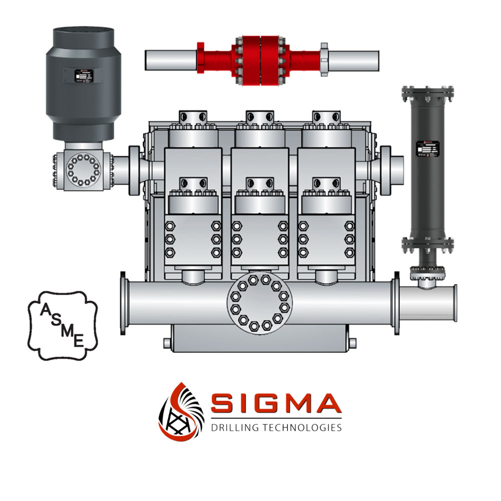
All pulsation dampeners utilize one of two methods for mitigating energy produced by reciprocating pumps; compression or exchange. The traditional gas-charged dampeners use a compressible gas cushion, either by a gas over liquid or gas-filled diaphragms, bladders, or cartridge. As the reciprocating pump produces pressure spikes, the gas compresses, thus absorbing the pressure difference and smoothing the pumped media flow. For maintenance free pulsation dampeners, rely on energy exchange. There is a common misconception regarding maintenance free pulsation control devices that the pumped media is compressible enough to absorb the reciprocating pumps’ pressure spikes. This is not true. However, the maintenance free pulsation dampeners work by utilizing the kinetic energy exchange. This kinetic energy exchange can only happen if the pulsation dampener’s volume is large enough to dissipate enough energy to reduce the adverse effects caused by the reciprocating pump. This is why maintenance free pulsation devices require massive volumes to be effective. Sigma Drilling Technologies has developed a pulsation dampening system that utilizes both methods for reducing the harmful effects of positive displacement pumps, both compression and exchange.

For more information about pulsation dampeners, we sat down with Brandon Dalrymple and Nathan Ackeret fromBlacoh Fluid Control(manufacturer of pulsation dampeners, surge suppressors, and inlet stabilizers), and asked them to answer a few of our customers’ most common questions about pulsation dampeners.
Pulsation dampeners absorb the energy from the pulse wave created by a positive displacement pump, much like a shock absorber on a vehicle. Absorbing those pulse waves protects pipe welds and supports, and system components from damage due to pressure or excess movement.
A pulsation dampener creates an area of low pressure in the system with enough volume to absorb the pulsation. The pulsation dampener has a membrane with a "cushion" of compressible gas/air behind it that flexes to absorb the pulse, allowing a laminar flow downstream of the dampener.
Pulsation dampeners are commonly used wherever a positive displacement pump discharges flow in an unsteady manner, and where the pulse is not desired for the piping system. Air operated double diaphragm, metering and hose/peristaltic pumps typically benefit from a pulsation dampener.
The type of pulsation dampener used is typically defined by where they are placed in the system, and what they need to do. For example, "pulsation dampeners" are on the downstream side of the pump, "inlet stabilizers" are on the inlet side of the pump, and an accumulator or "surge suppressor" is used next to a valve or other device that restricts the flow in a system.
This video shows where you would place an inlet stabilizer, and how it is used to reduce the pulsation with an air operated diaphragm pump in suction lift conditions.
If you"re experiencing problems with rattling pipes, intermittent flow, water hammer, or pulsations in your system, don"t ignore it. Take the steps necessary to control these symptoms to prevent system deterioration down the road.
Need help with pulsations or water hammer problems? Ask us about it! We gladly provide technical assistance to businesses in Wisconsin and Upper Michigan.
This equipment plays an important role as an accessory to Yamada air-operated double diaphragm pumps. The pulsation dampener serves to reduce pulsation produced in operation and to assure stable discharge flow and pressure.
When pulsations occur with pump operation, it will result in the pressure in Chamber Bbeing greater than that in Chamber A. The diaphragm will act as an air cushion and automatically adjust to this pressure change and absorb the pulsations.
This operation will shift the center rod position upwards and allow more air in Chamber Athrough the air inlet, returning the diaphragm to a neutral position. If liquid pressure decreases, air pressure in Chamber Acauses the diaphragm to move downward, shifting shaft location and changing valve position, releasing excess air pressure in Chamber Awhich returns diaphragm to a neutral position. This action causes a reduction in surges and pulsation caused by a air operated double diaphragm pumps

This website is using a security service to protect itself from online attacks. The action you just performed triggered the security solution. There are several actions that could trigger this block including submitting a certain word or phrase, a SQL command or malformed data.
My first days as an MWD field tech I heard horror stories surrounding what is commonly referred to as “pump noise”. I quickly identified the importance of learning to properly identify this “noise”. From the way it was explained to me, this skill might prevent the company you work from losing a job with an exploration company, satisfy your supervisor or even allow you to become regarded as hero within your organization if you’ve proven yourself handy at this skill.
“Pump noise” is a reference to an instability in surface pressure created by the mud pumps on a modern drilling rig, often conflated with any pressure fluctuation at a similar frequency to pulses generated by a mud pulser, but caused by a source external to the mud pulser. This change in pressure is what stands in the way of the decoder properly understanding what the MWD tool is trying to communicate. For the better part of the first year of learning my role I wrongly assumed that all “noise” would be something audible to the human ear, but this is rarely the case.
In an ideal drilling environment surface pressure will remain steady and all pressure increases, and decreases will be gradual. This way, when the pulser valve closes(pulses), it’s easily detectable on surface by computers. Unfortunately drilling environments are rarely perfect and there are many things that can emulate a pulse thus causing poor or inaccurate data delivery to surface. The unfortunate circumstance of this means drilling operations must come to halt until data can once again be decoded on surface. This pause in the drilling process is commonly referred to at NPT or non-productive time. For those of you unfamiliar these concepts, I’ll explain some of the basics.
A mud pulser is a valve that briefly inhibits flow of drilling fluid traveling through the drill string, creating a sharp rise and fall of pressure seen on surface, also known as a “pulse”.
Depending on if the drilling fluid is being circulated in closed or open loop, it will be drawn from a tank or a plastic lined reservoir by a series(or one) mud pumps and channeled into the stand pipe, which runs up the derrick to the Kelly-hose, through the saver sub and down the drill-pipe(drill-string). Through the filter screen past an agitator or exciter, around the MWD tool, through a mud motor and out of the nozzles in the bit. At this point the fluid begins it’s journey back to the drilling rig through the annulus, past the BOP then out of the flow line and either over the shale shakers and/or back in the fluid reservoir.
Developing a firm grasp on these fundamentals were instrumental in my success as a field technician and an effective troubleshooter. As you can tell, there are a lot of components involved in this conduit which a mud pulser telemeters through. The way in which many of these components interact with the drilling fluid can suddenly change in ways that slightly create sharp changes in pressure, often referred to as “noise”. This “noise” creates difficulty for the decoder by suddenly reducing or increasing pressure in a manner that the decoder interprets a pulse. To isolate these issues, you must first acknowledge potential of their existence. I will give few examples of some of these instances below:
Suction screens on intake hoses will occasionally be too large, fail or become unfastened thus allowing large debris in the mud system. Depending on the size of debris and a little bit of luck it can end up in an area that will inhibit flow, circumstantially resulting in a sudden fluctuation of pressure.
Any solid form of drilling fluid additive, if improperly or inconsistently mixed, can restrict the flow path of the fluid resulting in pressure increase. Most notably this can happen at the pulser valve itself, but it is not the only possible outcome. Several other parts of this system can be affected as well. LCM or loss of circulation material is by far the most common additive, but the least overlooked. It’s important for an MWD technician to be aware of what’s being added into the drilling fluid regardless if LCM isn’t present. Through the years I have seen serval other improperly mixed additives cause a litany of pressure related issues.
This specifically is a term used to refer to the mud motor stator rubber deterioration, tearing into small pieces and passing through the nozzles of the bit. Brief spikes in pressure as chunks of rubber pass through one or more nozzles of the bit can often be wrongly interpreted as pulses.
Sometimes when mud is displaced or a pump suction isn’t completely submerged, tiny air bubbles are introduced into the drilling fluid. Being that air compresses and fluid does not, pulses can be significantly diminished and sometimes non-existent.
Formation cuttings staying downhole can cause what is known as a pack-off of the anulus, which typically cause slower trends in pressure. A pack-off is less likely to cause significant decoding issues, but can.
Failed surface equipment such as transducers and transducer cables can occasionally allow current external to the circuit into the signal wire, resulting in what appears to be a pressure increase on the decoder. When experiencing poor decoding these are some of the first pieces of equipment to be replaced.
As many of you know the downhole mud motor is what enables most drilling rigs to steer a well to a targeted location. The motor generates bit RPM by converting fluid velocity to rotor/bit RPM, otherwise known as hydraulic horsepower. Anything downhole that interacts with the bit will inevitably affect surface pressure. One of the most common is bit weight. As bit weight is increased, so does surface pressure. It’s important to note that consistent weight tends to be helpful to the decoder by increasing the amplitude of pulses, but inconsistent bit weight, depending on frequency of change, can negatively affect decoding. Bit bounce, bit bite and inconsistent weight transfer can all cause pressure oscillation resulting in poor decoding. Improper bit speed or bit type relative to a given formation are other examples of possible culprits as well.
Over time mud pump components wear to the point failure. Pump pistons(swabs), liners, valves and valve seats are all necessary components for generating stable pressure. These are the moving parts on the fluid side of the pump and the most frequent point of failure. Another possible culprit but less common is an inadequately charged pulsation dampener. Deteriorating rubber hoses anywhere in the fluid path, from the mud pump to the saver sub, such as a kelly-hose, can cause an occasional pressure oscillation.
If I could change one thing about today’s directional drilling industry, it would be eliminating the term “pump noise”. The misleading term alone has caused confusion for countless people working on a drilling rig. On the other hand, I’m happy to have learned these lessons the hard way because they seem engrained into my memory. As technology improves, so does the opportunities for MWD technology companies to provide useful solutions. Solutions to aid MWD service providers to properly isolate or overcome the challenges that lead to decoding issues. As an industry we have come a lot further from when I had started, but there is much left to be desired. I’m happy I can use my experiences by contributing to an organization capable of acknowledging and overcoming these obstacles through the development of new technology.
If you run a mud rig, you have probably figured out that the mud pump is the heart of the rig. Without it, drilling stops. Keeping your pump in good shape is key to productivity. There are some tricks I have learned over the years to keeping a pump running well.
First, you need a baseline to know how well your pump is doing. When it’s freshly rebuilt, it will be at the top efficiency. An easy way to establish this efficiency is to pump through an orifice at a known rate with a known fluid. When I rig up, I hook my water truck to my pump and pump through my mixing hopper at idle. My hopper has a ½-inch nozzle in it, so at idle I see about 80 psi on the pump when it’s fresh. Since I’m pumping clear water at a known rate, I do this on every job.
As time goes on and I drill more hole, and the pump wears, I start seeing a decrease in my initial pressure — 75, then 70, then 65, etc. This tells me I better order parts. Funny thing is, I don’t usually notice it when drilling. After all, I am running it a lot faster, and it’s hard to tell the difference in a few gallons a minute until it really goes south. This method has saved me quite a bit on parts over the years. When the swabs wear they start to leak. This bypass pushes mud around the swab, against the liners, greatly accelerating wear. By changing the swab at the first sign of bypass, I am able to get at least three sets of swabs before I have to change liners. This saves money.
Before I figured this out, I would sometimes have to run swabs to complete failure. (I was just a hand then, so it wasn’t my rig.) When I tore the pump down to put in swabs, lo-and-behold, the liners were cut so badly that they had to be changed too. That is false economy. Clean mud helps too. A desander will pay for itself in pump parts quicker than you think, and make a better hole to boot. Pump rods and packing last longer if they are washed and lubricated. In the oilfield, we use a petroleum-based lube, but that it not a good idea in the water well business. I generally use water and dish soap. Sometimes it tends to foam too much, so I add a few tablets of an over the counter, anti-gas product, like Di-Gel or Gas-Ex, to cut the foaming.
Maintenance on the gear end of your pump is important, too. Maintenance is WAY cheaper than repair. The first, and most important, thing is clean oil. On a duplex pump, there is a packing gland called an oil-stop on the gear end of the rod. This is often overlooked because the pump pumps just as well with a bad oil-stop. But as soon as the fluid end packing starts leaking, it pumps mud and abrasive sand into the gear end. This is a recipe for disaster. Eventually, all gear ends start knocking. The driller should notice this, and start planning. A lot of times, a driller will change the oil and go to a higher viscosity oil, thinking this will help cushion the knock. Wrong. Most smaller duplex pumps are splash lubricated. Thicker oil does not splash as well, and actually starves the bearings of lubrication and accelerates wear. I use 85W90 in my pumps. A thicker 90W140 weight wears them out a lot quicker. You can improve the “climbing” ability of the oil with an additive, like Lucas, if you want. That seems to help.
Outside the pump, but still an important part of the system, is the pop-off, or pressure relief valve. When you plug the bit, or your brother-in-law closes the discharge valve on a running pump, something has to give. Without a good, tested pop-off, the part that fails will be hard to fix, expensive and probably hurt somebody. Pop-off valve are easily overlooked. If you pump cement through your rig pump, it should be a standard part of the cleanup procedure. Remove the shear pin and wash through the valve. In the old days, these valves were made to use a common nail as the shear pin, but now nails come in so many grades that they are no longer a reliable tool. Rated shear pins are available for this. In no case should you ever run an Allen wrench! They are hardened steel and will hurt somebody or destroy your pump.
One last thing that helps pump maintenance is a good pulsation dampener. It should be close to the pump discharge, properly sized and drained after every job. Bet you never thought of that one. If your pump discharge goes straight to the standpipe, when you finish the job your standpipe is still full of fluid. Eventually the pulsation dampener will water-log and become useless. This is hard on the gear end of the pump. Open a valve that drains it at the end of every job. It’ll make your pump run smoother and longer.

This website is using a security service to protect itself from online attacks. The action you just performed triggered the security solution. There are several actions that could trigger this block including submitting a certain word or phrase, a SQL command or malformed data.

This website is using a security service to protect itself from online attacks. The action you just performed triggered the security solution. There are several actions that could trigger this block including submitting a certain word or phrase, a SQL command or malformed data.
This present invention is directed to drilling wellbores in the earth, to systems for pumping drilling fluid (“mud”) for such operations, to mud pumping system modules with surge suppressing dampeners, and to methods of their use. DESCRIPTION OF THE RELATED
Known references disclose a wide variety of drilling systems, apparatuses, and methods including, but not limited to, the disclosures in U.S. Pat. Nos. 6,944,547; 6,918,453; 6,802,378; 6,050,348; 5,465,799; 4,995,465; 4,854,397; and 3,658,138, all incorporated fully herein for all purposes. Prior references disclose a wide variety of drilling fluid pumps (“mud pumps”) used in drilling operations and pump systems, for example, and not by way of limitation, those pumps and systems disclosed in U.S. Pat. Nos. 6,257,354; 4,295,366; 4,527,959; 5,616,009; 4,242,057; 4,676,724; 5,823,093; 5,960,700; 5,059,101; 5,253,987; in U.S. application Ser. No. 10/833,921 filed Apr. 28, 2004(all said U.S. references incorporated fully herein for all purposes). Known references disclose a variety of dampeners, accumulators, and surge suppressors; including, but not limited to, those disclosed in U.S. Pat. Nos. 4,299,253; 4,195,668; 2,757,689; 2,804,884; 3,674,053; 3,169,551; 3,674,053; 3,162,213; 2,380,866; 2,378,467; 2,397,248; 2,397,796; and 2,773,455—all incorporated fully herein for all purposes.
A drill bit carried at an end of a drillstring is rotated to form wellbores in the earth. Certain drillstrings include tubulars which may be drill pipe made of jointed sections or a continuous coiled tubing and a drilling assembly that has a drill bit at its bottom end. The drilling assembly is attached to the bottom end of the tubing or drillstring. In certain systems, to drill a wellbore, the drill bit is rotated (e.g., by a top drive, a power swivel, a rotary table system, or by a downhole mud motor carried by the drilling assembly). Drilling fluid, also referred to as “mud,” is pumped through the wellbore under pressure from a pit or container at the surface by a pumping system at the surface.
In certain known mud pump systems, suction and discharge modules have valves therein that selectively control fluid flow through the module in an intake (suction) mode in which piston apparatus creates a vacuum drawing drilling fluid into the module and in an output mode (Discharge) in which the piston apparatus creates pressure forcing drilling fluid out of the module. In the suction mode, a suction valve opens allowing drilling fluid into the module while a discharge valve remains closed. In the discharge mode, the pressure of the drilling fluid closes the suction valve and opens the discharge valve.
Both valves, the suction valve and the discharge valve, are subjected to the erosive and damaging effects of the flow of drilling fluid. The drilling fluid contains drilled cuttings and debris which can erode valve parts (e.g. seats, stems, valve members, seals, guide bushings, insert, liners, wear plates etc.). Also, mud pumps which can pump relatively hot drilling fluid at, e.g., 500 to 2000 gallons per minute, force the erosive drilling fluid against the valve parts at high velocities which add to the fluid"s damaging effects.
In many valves used in mud pump systems, a guide in the valve which is disposed across a flow path or guide fingers extending from a valve member into a valve seat guide a valve member so that valve member seats correctly and effectively against the valve seat. In many valves, the valve seat surface against which the valve member (or poppet) seats is, ideally, flat; and the surface of the valve member which sealingly abuts the flat seat surface of the valve seat is, correspondingly, and ideally, flat. A guide or guide fingers facilitates correct seating of the valve member"s flat seating surface against the valve seat"s flat seat surface. If either surface is not flat, or if one surface does not contact the other in a substantially parallel (flat surface to flat surface) manner, ineffective or inefficient valve operation may result.
The erosive and/or damaging effects of drilling fluid flow through a valve can damage the seating surfaces so that the ideal flat-surface-to-flat surface seating is not achieved. Also, the drilling fluid can damage a guide (e.g. ribs and a channel for receiving a stem or rod projecting from a valve member) or guide fingers so that the ideal surface seating is not achieved. In some instances, damage to a guide or to guide fingers results in a flat valve member surface contacting a flat seating surface at an angle so that effective valve closure is not possible or so that the valve is insufficiently closed for efficient operation. In some aspects, erosive drilling fluid flow renders initially-flat seating surfaces non-flat with resulting ineffective sealing and valve closure.
In many known mud pump valves, the valves are opened and closed by mechanically creating a vacuum or fluid pressure increase in the valve that overcomes a spring to allow a valve member to move. The movement of the valve member is not controlled, i.e., it is subject to a surge of fluid under pressure. As fluid pressure builds up to move a valve member, a corresponding amount of fluid builds up adjacent the valve. when the pressure is high enough, a relatively large charge of fluid goes through the valve at high velocity. This surge of fluid can have deleterious effects on valve parts. BRIEF SUMMARY OF THE INVENTION
The present invention, in at least certain embodiments, discloses systems for pumping a drilling fluid mixture, the drilling fluid mixture containing drilling fluid and solids, the systems having: a pump apparatus; the pumping apparatus having a body with a pumping chamber, an inlet and an outlet; a suction valve in the body for selectively controlling flow of the drilling fluid mixture in through the inlet; a discharge valve in the body for selectively controlling flow of the drilling fluid mixture out through the outlet; and a dampener system according to the present invention in fluid communication with the pumping chamber.
Such a pump system according to the present invention, in one aspect, includes: a base; a housing connected to the base, the housing having an interior; a liner within the housing, the liner expandable in response to fluid pressure; a piston/cylinder apparatus in fluid communication with the housing; the piston/cylinder apparatus having a movable piston movable in response to fluid flowing from the housing to the piston/cylinder apparatus; a torsion apparatus movably connected to the base, the piston movable to contact and to move the torsion apparatus in response to fluid flowing from the housing to the piston/cylinder apparatus; and the torsion apparatus movable by the piston from a first static position to a second position to dampen pulsations of fluid into the pumping chamber.
In one aspect, a pumping system according to the present invention has a dampener system according to the present invention which includes: a housing, the housing having an interior; a deformable bladder within the housing, the deformable bladder in fluid communication with the pumping chamber; and the deformable bladder deformable in response to pressure variation in the pumping chamber.
The present invention discloses, in certain aspects, dampeners for drilling fluid pumping systems which suppress and/or eliminate the damaging effects of undesirable pulsations or surges of drilling fluid passing through the systems. In certain aspects, the dampener has a liner with liquid therein which expands and contracts in response to the pressure of drilling fluid passing through a pumping system.
The present invention discloses, in certain aspects, dampeners for drilling fluid pumping systems in which the dampener has a liner with liquid therein which expands and contracts in response to the pressure of drilling fluid passing through a pumping system. In certain aspects, a dampener according to the present invention has a torsion apparatus that absorbs and then releases energy to facilitate the dampening of drilling fluid surges. In other aspects, a dampener system according to the present invention has an inflatable bladder surrounded by an expandable spring member, both the bladder and the spring member responsive to drilling fluid surges to suppress deleterious effects of such surges.
The present invention discloses, in certain aspects, modules for a drilling fluid pumping system which include a dampener for suppressing and/or eliminating the damaging effects of undesirable pulsations or surges of drilling fluid passing through the modules. In certain aspects, the dampener is within a block of the module that also contains suction and discharge valve assemblies within a module block.
The present invention discloses, in certain aspects, a drilling fluid pumping system, also known as a mud pump system, for pumping drilling fluid or mud used in wellbore operations which has pumping modules with valves that have non-flat seating surfaces. In certain aspects, such valves have a valve member or poppet that is movable with multiple degrees of freedom in any of which effective seating of the valve member against a valve seat is achieved. In particular aspects of such a valve, dual sealing is achieved by sealing of a valve member against both a valve seat and against a seal disposed in a valve seat.
In certain particular aspects of a mud pump system according to the present invention, a mud pump valve has a tapered spring biased against a valve member which enhances the free seating movement of a valve member.
The present invention discloses, in certain aspects, valves for a system for pumping a drilling fluid mixture, the drilling fluid mixture containing drilling fluid and solids, the valves having: a seat with a valve seat surface; a valve member with a member surface, part of the valve member movable to seat the member surface against the valve seat surface to prevent the flow of the drilling fluid mixture past the valve seat; a cartridge stem positioned with respect to the valve member, and a valve actuator within the cartridge stem for selectively moving the valve member. In certain aspects, the present invention discloses a system for pumping a drilling fluid mixture, the drilling fluid mixture containing drilling fluid and solids, the system having: a pump apparatus; the pumping apparatus having a body with an inlet and an outlet; a suction valve in the body for selectively controlling flow of the drilling fluid mixture in through the inlet; a discharge valve in the body for selectively controlling flow of the drilling fluid mixture out through the outlet; and a dampener within the body for inhibiting pulsations of fluid pumped from the pump apparatus In certain valves according to the present invention a valve actuator is used which is pneumatically powered without certain mechanically moving parts used in prior valves.
Accordingly, the present invention includes features and advantages which are believed to enable it to advance pumping system technology. Characteristics and advantages of the present invention described above and additional features and benefits will be readily apparent to those skilled in the art upon consideration of the following description of preferred embodiments and referring to the accompanying drawings.
Certain embodiments of this invention are not limited to any particular individual feature disclosed here, but include combinations of them distinguished from the prior art in their structures, functions, and/or results achieved. Features of the invention have been broadly described so that the detailed descriptions of embodiments preferred at the time of filing for this patent that follow may be better understood, and in order that the contributions of this invention to the arts may be better appreciated. There are, of course, additional aspects of the invention described below and which may be included in the subject matter of the claims to this invention. Those skilled in the art who have the benefit of this invention, its teachings, and suggestions will appreciate that the conceptions of this disclosure may be used as a creative basis for designing other structures, methods and systems for carrying out and practicing the present invention. The claims of this invention are to be read to include any legally equivalent devices or methods which do not depart from the spirit and scope of the present invention.
What follows are some of, but not all, the objects of this invention. In addition to the specific objects stated below for at least certain embodiments of the invention, other objects and purposes will be readily apparent to one of skill in this art who has the benefit of this invention"s teachings and disclosures. It is, therefore, an object of at least certain preferred embodiments of the present invention to provide new, useful, unique, efficient, nonobvious dampener systems for drilling fluid pumping systems and methods of their use;
The present invention recognizes and addresses the problems and needs in this area and provides a solution to those problems and a satisfactory meeting of those needs in its various possible embodiments and equivalents thereof. To one of skill in this art who has the benefits of this invention"s realizations, teachings, disclosures, and suggestions, various purposes and advantages will be appreciated from the following description of certain preferred embodiments, given for the purpose of disclosure, when taken in conjunction with the accompanying drawings. The detail in these descriptions is not intended to thwart this patent"s object to claim this invention no matter how others may later attempt to disguise it by variations in form, changes, or additions of further improvements.
The Abstract that is part hereof is to enable the U.S. Patent and Trademark Office and the public generally, and scientists, engineers, researchers, and practitioners in the art who are not familiar with patent terms or legal terms of phraseology to determine quickly, from a cursory inspection or review. the nature and general area of the disclosure of this invention. The Abstract is neither intended to define the invention, which is done by the claims, nor is it intended to be limiting of the scope of the invention or of the claims in any way.
It will be understood that the various embodiments of the present invention may include one, some, or all of the disclosed, described, and/or enumerated improvements and/or technical advantages and/or elements in claims to this invention.
Certain aspects, certain embodiments, and certain preferable features of the invention are set out herein. Any combination of aspects or features shown in any aspect or embodiment can be used except where such aspects or features are mutually exclusive. BRIEF DESCRIPTION OF THE DRAWINGS
A more particular description of embodiments of the invention briefly summarized above may be had by references to the embodiments which are shown in the drawings which form a part of this specification. These drawings illustrate embodiments preferred at the time of filing for this patent and are not to be used to improperly limit the scope of the invention which may have other equally effective or legally equivalent embodiments.
FIG. 2F is a perspective view, partially cutaway, of a pump module according to the present invention with valve assemblies according to the present invention.
Certain embodiments of the invention are shown in the above-identified figures and described in detail below. Various aspects and features of embodiments of the invention are described below and some are set out in the dependent claims. Any combination of aspects and/or features described below or shown in the dependent claims can be used except where such aspects and/or features are mutually exclusive. It should be understood that the appended drawings and description herein are of certain embodiments and are not intended to limit the invention or the appended claims. On the contrary, the intention is to cover all modifications, equivalents and alternatives falling within the spirit and scope of the invention as defined by the appended claims. In showing and describing these embodiments, like or identical reference numerals are used to identify common or similar elements. The figures are not necessarily to scale and certain features and certain views of the figures may be shown exaggerated in scale or in schematic in the interest of clarity and conciseness.
As used herein and throughout all the various portions (and headings) of this patent, the terms “invention”, “present invention” and variations thereof mean one or more embodiments, and are not intended to mean the claimed invention of any particular appended claim(s) or all of the appended claims. Accordingly, the subject or topic of each such reference is not automatically or necessarily part of, or required by, any particular claim(s) merely because of such reference. So long as they are not mutually exclusive or contradictory any aspect or feature or combination of aspects or features of any embodiment disclosed herein may be used in any other embodiment disclosed herein. DETAILED DESCRIPTION OF THE INVENTION
The system 500 shown in FIG. 1 includes a derrick 502 from which extends a drillstring 504 into the earth 506. The drillstring 504, as is well known, can include drill pipes and drill collars. A drill bit 512 is at the end of the drillstring. A rotary system 514, top drive system 526, and/or a downhole motor 532 (“fluid motor”, “mud motor”) may be used to rotate the drillstring 504 and the drill bit 512. A typical drawworks 516 has a cable or rope apparatus 518 for supporting items in the derrick 502. A mud pump system 522 according to the present invention with one, two, three-to-ten, or more mud pumps 521 according to the present invention each with pumping modules with one or two valves according to the present invention supplies drilling fluid 524 to the drillstring 504. Drilling forms a wellbore 530 extending down into the earth 506. Each mud pump 521 has at least one valve 501 according to the present invention or (as shown in FIG. 1A schematically) multiple pumping modules 503 each with a suction valve 505 according to the present invention and a discharge valve 506 according to the present invention. Each mud pump 521 has a main crank shaft 521 c.
During drilling, the drilling fluid 524 is pumped by pump(s) 521 of the mud pump system 522 into the drillstring 504 (thereby operating a downhole motor 532 if such an optional motor is used). Drilling fluid 524 flows to the drill bit 512, and then flows into the wellbore 530 through passages in the drill bit 512. Circulation of the drilling fluid 524 transports earth and/or rock cuttings, debris, etc. from the bottom of the wellbore 530 to the surface through an annulus 527 between a well wall of the wellbore 530 and the drillstring 504. Cuttings and debris are removed from the drilling fluid 524 with equipment and apparatuses not shown, and it is re-circulated from a mud pit or container 528 by the pump(s) of the mud pump system 522 back to the drillstring 506. Also, some desirable solids may be added to the drilling fluid.
A system 10 according to the present invention as shown in FIGS. 2A and 2B has a main housing 12 mounted on a base 8 with an optional crane system 20 for lifting and moving system parts. A pedestal 21 of the crane system 20 is rotatably mounted on a bearing assembly 22 on the housing 12. A lift apparatus 23 is movably mounted on a beam 24 and a support 25 extends down from the lift apparatus 23. A chain hoist lift may be used with the structure shown which is attached to the support 25. Motors 14 each drive pinions 16 which in turn drive a drive gear 18 (see FIG. 3C) to move pistons 19 for six removable pump modules 650 (as described below; may be any module disclosed herein and/or may have any valve assembly or valve assemblies disclosed herein). A pressure relief apparatus (e.g. one or more relief valves) is provided for the modules 650 and, as shown, in one aspect, for each of the six modules 650 there is a pressure relief valve 13. Optional rails 15 project up from the housing 12.
An oil pump 2 pumps lubricating oil to various parts of the system. A water pump 4 pumps water to a filtration system (not shown) and a cooler (not shown). The pumps are mounted on pump mounts 8 bconnected to the base 8. Doors 3 and 5 (one each for each pump system 30) provide access to various internal parts of the system 10. Drilling fluid enters the system 10 through an inlet 7 and is pumped out via the modules 650 to a main outlet 9.
The modules 650 have a body 602 with a first bore 602 aand a second bore 602 b. A discharge valve assembly according to the present invention is in the first bore and a suction valve assembly according to the present invention is in the second bore. With a piston fluid is pumped into a chamber 652 of the module 650 via an inlet port 604 and is discharged from the module 650 into a discharge conduit 634 via an outlet port 606.
FIG. 2F shows the relative positions of two valve assemblies 100 a, 100 b(like the valve assembly 100) according to the present invention as they are present in a block of a mud pump module. The valve assemblies 100 a, 100 b(which may be any valve assemblies disclosed herein) are in bores 642, 643, respectively, in a block 644. The block 644 can be used in a system like that of FIG. 2A.
FIGS. 2G-2I show two valve assemblies 100 x, 100 y(like the valve assembly 100 a, FIG. 9A; may be any valve assembly according to the present invention) as they are disposed in a block B (shown in dotted line; may be any suitable block or body; including, but not limited to, the body 602 or block 644 referred to above) of a mud pump system. Fluid is sucked in by action of the suction valve assemblies 100 xthrough a suction inlet 400 and discharged by action of the discharge valve assembly 100 ythrough a discharge outlet 402. The fluid is received in a pumping chamber 404.
Fluid pumped from the chamber 404 can impact parts of the discharge valve 100 x. Optionally, an accumulator/dampener 410, positioned within the block B, is in fluid communication with the pumping chamber 404. The accumulator/dampener 410 reduces undesirable pulsations of fluid under pressure from the pumping chamber 404. Any suitable known accumulator/dampener may be used.
FIGS. 3A and 3B show a valve assembly 100 according to the present invention which can serve as a suction valve or a discharge valve for a mud pump system (e.g., but not limited to, the suction valve assembly 680 and the discharge valve assembly 630 described above; or the suction valve 100 xand the discharge valve 100 ydescribed above). FIG. 4 shows top portions of the valve assembly 100.
The valve assembly 100 has a hollow cartridge stem 102 with an interior channel 104 within which are located a valve actuator 130 and an adapter 106. A spring support 108, connected to a flange 110 of the cartridge stem 102, has an end 112 which is encompassed by part of an expansion spring 120 an end of which abuts the spring support 108.
A poppet (or curved valve member) 114 rests on a support 116. An end 122 of the spring 120 abuts and is biased against a bottom of the support 116. A ball 118 rests on a ball support 124 which rests on the support 116. A cable 128 (i.e. a non-rigid connector) (made of any known cable material) connected to the ball 118 passes through a hole 140 in and through the support 124, through a hole 142 in the support 116, through the spring 120, through a hole 143 in the spring support 108, through a hole 144 in the adapter 106 which is and is connected to the adapter 106 connected to an actuator 130.
A washer 151 above the ball 118 abuts an underside 115 of the poppet 114. A recess 152 within the poppet 114 houses the ball 118, the washer 151 and the support 124. The poppet 114 has a tapered surface 136 for sealingly abutting a valve seat and a seal of a valve seat as described below.
The poppet 114 is movable toward and away from a valve seat 160. The valve seat 160 has a channel 162 for fluid flow therethrough. The poppet 114 selectively closes off and opens up the channel 162 to fluid flow. Part of the channel 162 is sized and configured for the poppet 114. A surface 166 of the valve seat 160 is positioned to seal against the tapered of the surface 136 of the poppet 114. Optionally, there are no guide fingers projecting from the poppet 114 (although it is within the scope of the present invention to use them); and there are no arms or ribs across the valve seat (it is unobstructed) for receiving and stabilizing a rod, stem or neck projecting from a poppet; and there is no rod, neck or stem projecting from the poppet. Thus, flow through the channel 162 is unobstructed by such parts which are present in many prior valves.
A recess 168 around the valve seat 160 holds a seal 169. Part of the surface 136 of the poppet 114 sealingly abuts the seal 169 when the valve assembly is closed, preventing fluid flow. Thus dual sealing is achieved.
The poppet 114 has a range of freedom of movement within the channel 162 of the valve seat 160. However the poppet 114 is located within and with respect to the valve seat 160, part of the outer tapered surface 136 of the poppet 114 will sealingly abut the seal 169 and the surface 136 will sealingly abut the surface 166. The poppet 114 can be aligned (or not) with the valve seat 160, but either way an effective seal is maintained with part of the surface 136 sealed against the seal 169. Movement of the poppet 114 on the ball 118 and the sizing and configuration of the various parts contribute to permissible freedom of movement of the poppet 114 without sacrificing the sealing necessary to close the valve assembly.
FIG. 5 shows the valve actuator 130 which can be, in certain aspects, any suitable known controllable, valve actuator, e.g., but not limited to “muscle” apparatuses, pneumatic cylinder actuators, hydraulic cylinder actuators, and electromagnetic actuators.
In one aspect, as shown in FIG. 5, the valve actuator 130 is a controlled, pneumatically powered actuator known as a FESTO (TRADEMARK) “muscle” actuator. The actuator 130 has an expandable hose 132 mounted between two bases 134, 135. Air under pressure is introducible into the interior of the hose 132 through a channel 137 in a pneumatic coupling 139. The upper base 134 is connected to an adapter support 127 to which the adapter 106 is secured.
As shown in FIG. 5, air under pressure has not yet been applied within the hose 132. Once air is applied the hose moves outwardly, effectively moving the top base 134 toward the lower base 135 and thereby pulling the adapter 106 to pull the cable 128 and move the poppet 114 out of sealing contact with the valve seat 160 against the force of the spring 120.
FIG. 6 shows one embodiment, a spring 120 a, of a spring 120. As compared to prior known spring designs, the spring 120 ahas a spring body with a smaller spring diameter, a, and with a higher spring force; but the wire diameter is relatively large, e.g. 0.22 inches, which results in the higher spring force. Use of an actuator like the actuator 130, FIG. 5, makes it possible to use a spring with the increased spring force (with the increased wire diameter). The overall diameter, b, of the spring 120 ais relatively smaller than prior springs because the spring 120 adoes not have to accommodate the relatively large necks of certain prior valve members. Certain prior mud pump valve springs reached a known resonant frequency (e.g. about 40 Hz to 43 Hz) creating poppet oscillations that resulted in an improperly seated poppet and in fluid pulsations transmitted downstream of a valve assembly. Due to its size and weight, the spring 120 ahas a higher natural frequency than those prior springs which resonate around 40 Hz and, thus, more force is required to resonate the spring 120 a. In certain aspects the spring 120 (or 120 a; or the spring 120 b, FIG. 7A) is sized and configured so its natural resonant frequency is about 25% higher than that of certain known springs (e.g., in one aspect 50 Hz vs 43 Hz). This reduces the chance of flow-induced resonance in the valve assembly with such a spring; provides better, more stable control of the valve assembly"s poppet; and provides more positive seating of the poppet against the valve seat.
FIGS. 7A and 7B show a spring 120 baccording to the present invention which has a spring body 120 cand an end tapered portion 120 dwhich abuts a support (e.g. like the support 116, FIG. 3A). The tapered portion 120 d, since it is narrower than a base 120 eof the spring 120 b, contributes to the freedom of movement of the poppet 114 (e.g. as in FIG. 8A).
FIGS. 8A and 8B illustrate steps in the operation of a valve assembly 100 (which has a spring 120 b, although any suitable spring may be used). As shown in FIG. 8A, air under pressure has not yet been applied within the hose 132 and the and the spring 120 burges the poppet 114 into sealing contact with the seal 169 and with the valve seat 160. The valve assembly 100 is closed to fluid flow therethrough. Fluid pressure also forces the poppet against the valve seat. On the discharge side of the valve seat at the beginning of the pumping/compression part of a cycle, the spring 120 band the fluid within a discharge manifold pushes the poppet 114 against the seat. This continues until the pressure within the discharge manifold drops below the pressure within the pumping cylinder and/or until the actuator 130 is commanded to open. On the suction side, the fluid within the pumping cylinder pushes the poppet 114 against the seat 160 again during the compression part and until the actuator 130 is commended to open the valve. When the “muscle” of the actuator 130 is not expanded, there is residual air trapped between the commanding valve and the actuator 130. The pressure of this trapped air is close to the pressure that existed in this line at the moment of exhausting the air and closing off the valve"s exhaust port. When the actuator is flexed, there is air at a pressure that is sufficient to open the valve, e.g. 110 psi. The actuator and air lines are filled in order to decrease the actuator"s response time—the time to respond to a commanding pressure. If the actuator is completely empty or, with, e.g. air at atmospheric pressure, it will take slightly longer for the actuator to respond, because when such a high pressure is applied the cavity would have to be filled with air first, then compress the air just introduced to a high enough pressure to barely stretch the hose 132 and only after that will the hose 132 change its length or respond to a commanding pressure.
As shown in FIG. 8B, air under pressure from an air supply 200 (with a proportional control valve 200 p) has been applied within the hose 132 causing it to expand and pulling the cable 128 away from the valve seat 160. In so doing, the poppet 114 is moved out of sealing contact with the seat 160 and the seal 169 of the valve seat 160 and the valve assembly is opened to fluid flow permitting fluid to flow into and out from a mud pump module housing the valve assembly.
It is advantageous that the poppet is part of the valve cartridge. During assembly, when the pump is assembled for the first time, it is much easier to have a preassembled valve cartridge and, without adjustments, to insert and bolt it in and have it immediately become functional. Moreover, in servicing the valve, it is much easier to extract the entire cartridge, versus bits, individual parts, and/or pieces. In certain current designs, a poppet/valve has a pseudo cartridge design in the sense that the valve has no restricting elements to keep it attached to the cartridge. In other words, the cartridge can be loosely put together prior to assembly and it can be inserted as a cartridge being secured to the body by bolts. However, if during this assembly process, or later on during servicing the valve, this cartridge is turned upside down, the valve itself can become loose and fall to the ground.
Often in such prior systems there is no element like a snap ring to secure the valve to the cartridge. It is also advantageous that the seal is part of the valve housing. It is easier to have the seat part of a block that can be preassembled to the pump and, later on, during a later step in manufacturing, to bolt on to it a subassembly like the valve cartridge.
In designs according to the present invention, seals, e.g. the seal 169, do not resonate. According to the present invention, such seals are surrounded by a support and have no extraneous or “banging” features which could be excited by a surrounding flow stream.
In certain aspects according to the present invention, poppets and seats are made of ceramics which do not rust. In certain particular aspects, an alumina based ceramic offers very high strength and good wear resistance. In other aspects, a boron carbide ceramic can be used which has excellent erosion wear resistance. Both of these two ceramics have a higher erosion resistance then steel. In certain aspects the poppets of assemblies according to the present invention are made with a steel core surrounded by a ceramic. The steel core supports the Belleville washers and can have cut threads into it. A ceramic outer skin provides erosion resistance. In certain aspects, the special profiles facilitate the flow opening and closing the valve gradually.
In certain current designs, valves have two parallel surfaces. Often these surfaces form a seal that is part of conical bodies; i.e. the seal has a conical machined surface against which is pushed a poppet. The poppet"s sealing surface is also conical so that, at every instance, the seat"s and poppet"s sealing surfaces are parallel. During discharge, when the two bodies are separating and, thus, allowing the fluid to flow from the pumping chamber into the discharge manifold, the fluid is squeezed in between these flat surfaces. During this phase the fluid"s velocity can be greatly increased as it passes from a large cross section of the pumping chamber into a small one with parallel surfaces of the valve"s passage way. Moreover, because there is no controlling actuator, such a valve can open suddenly when the fluid"s pressure exerts onto the valve"s face a force slightly higher than that developed by the spring acting on the opposite face. As the fluid leaves at high velocity, it enters into a larger cross section that is the discharge manifold The high velocity and energy fluid acts almost like a piston in this case and pushes an adjacent block of fluid along the discharge line. This sudden move of a significant block of fluid can create a “bang” or a specifically loud noise almost like a pounding. This repeated banging/pounding can have detrimental effects on the drill line or other equipment.
In certain valve assemblies according to the present invention, the flat parallel surfaces are replaced by curved ones. Additionally, there is a controlling actuator that can open the valve before pressure in the pumping chamber reaches a value high enough to counteract the spring and, thus, to open the vale. Pressure at which the fluid leaves the pumping chamber is greatly reduced. Being formed in between two curved surfaces, the valve"s passage way flow characteristics do not impart a high velocity/energy to the fluid stream. Consequently, the fluid enters and leaves the discharge manifold and line respectively in a more dispersed manner. There is no “bang” as in certain previous valves because the fluid does not flow in discrete “blocks”.
The control system CS controls the air supply 200 and, thus, controls the valve assembly 100. This is in contrast to prior valves in which fluid flow opens and closes the valve. In one aspect, the control system controls the speed with which the parts move and thereby controls the speed of opening and of closing off the valve. Using appropriate software programming of programmable media in the control system, the control system controls an electro proportional valve control (e.g. the valve 200 p. FIG. 8B) that, in turn, controls the amount of air that enters or leaves the actuator 132. Consequently, the control system controls how fast, how long and how much the valve is opened. Gradual opening and closing is possible which reduces pressure pulsations. Each pump shaft (crankshaft) may have a speed sensor in communication with the control system (e.g. a sensor 521 s, FIG. 1). In systems with electric motors that drive the crankshaft(s), the motors are commanded through software in the control system and the same speed control signal can be broadcast to the control system. A dedicated speed sensor or a linear displacement transducer installed in every cylinder provides information for a closed loop control system (usable, e.g., to diagnose a pump in case of failure). With valve assemblies according to the present invention, the valves are not connected to the crankshaft.
The control system has programmable media, e.g. in a computer, computers, and/or PLC(s). In one aspect, the control system is preloaded with a program that includes a defining equation and a curve fitter. The defining equation is a function of pump shaft speed. The curve fitter compares the curve generated by the defining equation with an “ideal” curve desired to drive the valve The ideal curve usually represents the valve"s speed, or acceleration, or opening and/or, a different relevant parameter plotted versus time. The output from the control system drives a proportional valve, a valve that controls the actuator 130, e.g., in one aspect, supply air into a FESTO (TRADEMARK) “muscle”. Thus, the valve being actuated closely follows the preprogrammed curve/equation and the valve opens or closes at a certain velocity or acceleration, or that it opens at a certain rate over the duration of a pumping cycle. The opening or closing rate can be constant or variable. That is, the valve can start opening at a certain low rate followed by a higher rate followed by a different rate, and so on.
In one aspect, during a cycle the valve tends to follow a certain bell-shaped curve. Thus, the valve starts opening at a low rate followed at the very next instance by a slightly higher rate and in the next instance by an even higher rate and so on. All this is followed on the descending side of the curve by a lower rate followed by a slightly lower rate and so on until the valve closes. By introducing or expelling fluid into or from the pumping chamber at certain times the pump"s behavior is changed or the pump"s flow is measurable.
The mechanical equivalent of controlling a valve"s opening rate is a cam. The cam, through its profile, controls how fast and in what relationship relative to another element, e.g. a crankshaft, the valve will open or close. In other words, it controls the valve"s rate (displacement versus time). However, a cam"s profile can not be changed very easily because it is cut in metal. A practical method is to introduce a hydraulically actuated push rod or cam follower in between the cam and valve. Thus, the rate can change at will within a limited range. In the control strategy according to the present invention there is no piece of hardware/cam that limits the valve"s rate. Consequently, in the proposed actuation and control strategy, the desired curve can be changed on the fly as long as the controller, e.g. a computer or PLC, can accept/support it. Programmability makes this equivalent to an infinitely variable profile cam shaft and the pump"s output flow and vibration can be controlled. (An undesirable consequence of output flow in certain prior systems is component failure, e.g. due to cavitation.)
With the curved mating sealing surfaces of the valve seat and poppet, any contact results in an effective seal. Pressure fluctuations generated in or by prior art valves are reduced or eliminated and valve control reduces pressure fluctuation in the discharge line during pump operation.
Systems according to the present invention provide a fail safe mode. If a valve assembly according to the present invention that is inserted fails, then, for safety reasons, the pump continues working at either reduced or normal parameters until it is safe to stop it for service. In systems according to the present invention, if the actuator fails, e.g. if the muscle fails, it breaks or bursts, the valve will operate unrestricted (e.g. as a current known design valve). Thus, the pump can continue working at almost the same parameters until it is safe to stop it.
FIGS. 9A and 9B show a valve assembly 100 a, like the valve assembly 100 (like numerals indicate like parts) with a spring 120 band a poppet 114 a. The poppet 114 ahas a nose 114 nprojecting from a poppet body 114 b. The nose 114 nprojects into the flow channel 162 of the valve seat 160. In certain aspects, in systems according to the present invention the surface on the valve seat becomes, advantageously, more elastic. In a seal, two surfaces or edges are pushed against each other by a force. This acting force can be perpendicular to or at an arbitrary angle relative to the sealing surfaces. In systems according to the present invention the sealing bodies are the rubber seal and the poppet in one instance and, the seat itself and the poppet in a second instance. During a valve closing cycle, the first seal occurs in between a rubber O-ring and poppet. The acting force is axial relative to the poppet, but it is at an angle relative to the edge of contact between the two curved surfaces of the O-ring and poppet respectively. When the two bodies come into contact, at the point of contact, the vector components of this acting force are a normal to curved surfaces component and a tangential to curve components. This tangential component will stretch the rubber (the over hanging part of it) instead of purely compressing it. With the rubber O-ring being surrounded/supported by the seat"s rigid body, the rubber will take a very high force in compression as the normal-to-curved surfaces vector component. The rubber becomes


 8613371530291