
how does a mud pump pulsation dampener work pricelist
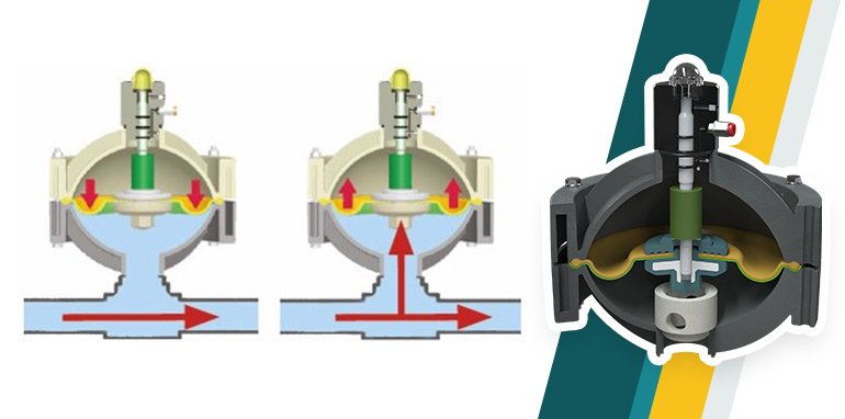
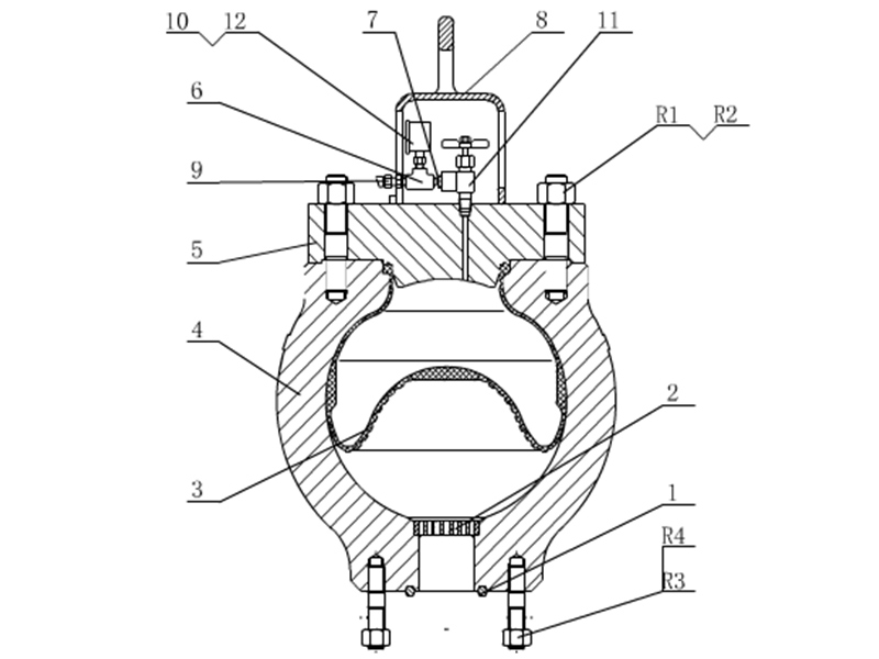
All pulsation dampeners utilize one of two methods for mitigating energy produced by reciprocating pumps; compression or exchange. The traditional gas-charged dampeners use a compressible gas cushion, either by a gas over liquid or gas-filled diaphragms, bladders, or cartridge. As the reciprocating pump produces pressure spikes, the gas compresses, thus absorbing the pressure difference and smoothing the pumped media flow. For maintenance free pulsation dampeners, rely on energy exchange. There is a common misconception regarding maintenance free pulsation control devices that the pumped media is compressible enough to absorb the reciprocating pumps’ pressure spikes. This is not true. However, the maintenance free pulsation dampeners work by utilizing the kinetic energy exchange. This kinetic energy exchange can only happen if the pulsation dampener’s volume is large enough to dissipate enough energy to reduce the adverse effects caused by the reciprocating pump. This is why maintenance free pulsation devices require massive volumes to be effective. Sigma Drilling Technologies has developed a pulsation dampening system that utilizes both methods for reducing the harmful effects of positive displacement pumps, both compression and exchange.

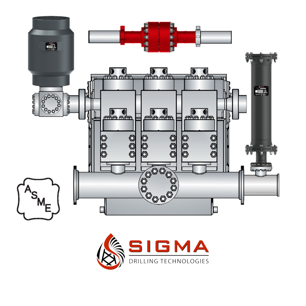
The Charge Free Dampening System™ is the first and only complete dampening system designed for maximum performance and cost savings. With the highest pressure rating at 10,000 psi, the CFD System far surpasses any pulsation control equipment in the drilling market today. Sigma’s system utilizes both appendage and flow-through technologies and yet still maintains the most compact design.
This multistage system utilizes several of Sigma’s advanced products that are proven to maximize efficiencies and upgrade operations of any reciprocating pumping system by themselves.
By protectively coating both inside and outside the system’s Charge Free Stabilizer™ and the Charge Free Dampener™, the system is entirely corrosion-resistant. The Charge Free Dampening System™ is easily the most protected pulsation equipment available.
The advantage of the CFD System’s small size, durability, and performance is combined with the fact the system requires no gas charging. The utilization of the Charge Free Conversion Kit® maximizes the dampening effects of the system without the need for nitrogen charging.
The Charge Free Dampening System™ is categorically the most sophisticated pulsation control available for your rigs’ pumping operations. With the introduction of the CFD System, Sigma Drilling Technologies proves to be the authority on state-of-the-art advancements in pulsation control technologies.
Mud Pump Pulsation Dampener is usually installed on the discharge line to reduce the fluctuation of pressure and displacement of the drilling mud pump.
Mud Pump Pulsation Dampener is a pneumatic device built into the outflow line of each UUD pump to dampen the pressure fluctuations resulting from the action of the pump. Although presented as a surge tank, this device is really a device that can be tuned to greatly diminish the output pulsations transmitted downstream from the mud pump. Unfortunately, the effectiveness of the pulsation dampener is a function of both output pump pressure and frequency of the pump pulsations.

Xi"an KINGWELL OILFIELD MACHINERY Co., Ltd. (KINGWELL) is a highly reputable supplier for oilfield equipment and services to Oil & Gas industries and provides complete solutions.
With over 10 years developing, we were developed from the beginning drilling service to manufacture factory who produce OCTG, drilling tools, DST tools and Solid control products.
KINGWELL have experienced team, stronger enough to meet any challenge, we do believe honest is the base of business and cooperation; our aim is to build solid relationship with any part of honest. kingwell can provide highly efficient services to its clients resulting in accurate and timely deliveries at the best prices. Our products have been exported to Europe, American and Middle East.

We have strong technical force, advanced processing equipment, and engage in technicalexchanges and cooperation with foreign companies and Universities.
Our products are exported to Europe, America, theMiddle East, South America, Southeast Asia, Australia etc, obtained the customer affirmation and the faith.
We always focus on good quality and excellentservice, comply strictly with international trade practice, to be aworld-class petroleum equipment supplier.
A quintuplex pump has a crankshaft supported in the pump by external main bearings. The crankshaft has five eccentric sheaves, two internal main bearing sheaves, and two bull gears.
A quintuplex pump is central to oil drilling and exploration due to the nature of operations. This pump circulates the mud to and from the surface, supporting the process for oil well operations.
The quintuplex pump is designed to circulate mud or drilling fluid under great pressure down the drill hole and back up. The pump is a reciprocating model that features five pistons, hence the name quintuplex mud pump. The right degree of pressure and precision is crucial for efficient well operations.
Despite the fact that all mud pumps have pulsation dampeners, noise levels are likely to be high and require modifications to keep noise pollution levels low. This is important, considering the long-running hours of equipment and the need to protect personnel from constant and high noise levels. With a quintuplex mud pump, the pulsation noise and the mud telemetry noise come down by as much as half, making operations less noisy.
Quintuplex pumps can be used in various applications including salt water disposal, descaling, high pressure pumping, Frac pumping, pipeline transfers in the Oil & Gas, Agriculture, Mining, Municipal and Manufacturing sectors.
Mud pumps comes in a variety of sizes and configurations but for the typical petroleum drilling rig, the triplex (three piston/plunger) mud pumps are the pump of choice. Duplex mud pumps (two piston/plungers) have generally been replaced by the triplex pump, but are still common in developing countries. Two later developments are the hex pump with six vertical pistons/plungers, and various quintuplex’s with five horizontal piston/plungers.
Duplex, triplex and quintuplex pumps all have an enviable history of sound engineering, designed to exceed the rigorous requirements of API 674 and customer satisfaction.

Mechanical pumps serve in a wide range of applications such as pumping water from wells, aquarium filtering, pond filtering and aeration, in the car industry for water-cooling and fuel injection, in the energy industry for pumping oil and natural gas or for operating cooling towers and other components of heating, ventilation and air conditioning systems. In the medical industry, pumps are used for biochemical processes in developing and manufacturing medicine, and as artificial replacements for body parts, in particular the artificial heart and penile prosthesis.
When a pump contains two or more pump mechanisms with fluid being directed to flow through them in series, it is called a multi-stage pump. Terms such as two-stage or double-stage may be used to specifically describe the number of stages. A pump that does not fit this description is simply a single-stage pump in contrast.
In biology, many different types of chemical and biomechanical pumps have evolved; biomimicry is sometimes used in developing new types of mechanical pumps.
Pumps can be classified by their method of displacement into positive-displacement pumps, impulse pumps, velocity pumps, gravity pumps, steam pumps and valveless pumps. There are three basic types of pumps: positive-displacement, centrifugal and axial-flow pumps. In centrifugal pumps the direction of flow of the fluid changes by ninety degrees as it flows over an impeller, while in axial flow pumps the direction of flow is unchanged.
Some positive-displacement pumps use an expanding cavity on the suction side and a decreasing cavity on the discharge side. Liquid flows into the pump as the cavity on the suction side expands and the liquid flows out of the discharge as the cavity collapses. The volume is constant through each cycle of operation.
Positive-displacement pumps, unlike centrifugal, can theoretically produce the same flow at a given speed (rpm) no matter what the discharge pressure. Thus, positive-displacement pumps are constant flow machines. However, a slight increase in internal leakage as the pressure increases prevents a truly constant flow rate.
A positive-displacement pump must not operate against a closed valve on the discharge side of the pump, because it has no shutoff head like centrifugal pumps. A positive-displacement pump operating against a closed discharge valve continues to produce flow and the pressure in the discharge line increases until the line bursts, the pump is severely damaged, or both.
A relief or safety valve on the discharge side of the positive-displacement pump is therefore necessary. The relief valve can be internal or external. The pump manufacturer normally has the option to supply internal relief or safety valves. The internal valve is usually used only as a safety precaution. An external relief valve in the discharge line, with a return line back to the suction line or supply tank provides increased safety.
Rotary-type positive displacement: internal or external gear pump, screw pump, lobe pump, shuttle block, flexible vane or sliding vane, circumferential piston, flexible impeller, helical twisted roots (e.g. the Wendelkolben pump) or liquid-ring pumps
Drawbacks: The nature of the pump requires very close clearances between the rotating pump and the outer edge, making it rotate at a slow, steady speed. If rotary pumps are operated at high speeds, the fluids cause erosion, which eventually causes enlarged clearances that liquid can pass through, which reduces efficiency.
Hollow disk pumps (also known as eccentric disc pumps or Hollow rotary disc pumps), similar to scroll compressors, these have a cylindrical rotor encased in a circular housing. As the rotor orbits and rotates to some degree, it traps fluid between the rotor and the casing, drawing the fluid through the pump. It is used for highly viscous fluids like petroleum-derived products, and it can also support high pressures of up to 290 psi.
Vibratory pumps or vibration pumps are similar to linear compressors, having the same operating principle. They work by using a spring-loaded piston with an electromagnet connected to AC current through a diode. The spring-loaded piston is the only moving part, and it is placed in the center of the electromagnet. During the positive cycle of the AC current, the diode allows energy to pass through the electromagnet, generating a magnetic field that moves the piston backwards, compressing the spring, and generating suction. During the negative cycle of the AC current, the diode blocks current flow to the electromagnet, letting the spring uncompress, moving the piston forward, and pumping the fluid and generating pressure, like a reciprocating pump. Due to its low cost, it is widely used in inexpensive espresso machines. However, vibratory pumps cannot be operated for more than one minute, as they generate large amounts of heat. Linear compressors do not have this problem, as they can be cooled by the working fluid (which is often a refrigerant).
Reciprocating pumps move the fluid using one or more oscillating pistons, plungers, or membranes (diaphragms), while valves restrict fluid motion to the desired direction. In order for suction to take place, the pump must first pull the plunger in an outward motion to decrease pressure in the chamber. Once the plunger pushes back, it will increase the chamber pressure and the inward pressure of the plunger will then open the discharge valve and release the fluid into the delivery pipe at constant flow rate and increased pressure.
Pumps in this category range from simplex, with one cylinder, to in some cases quad (four) cylinders, or more. Many reciprocating-type pumps are duplex (two) or triplex (three) cylinder. They can be either single-acting with suction during one direction of piston motion and discharge on the other, or double-acting with suction and discharge in both directions. The pumps can be powered manually, by air or steam, or by a belt driven by an engine. This type of pump was used extensively in the 19th century—in the early days of steam propulsion—as boiler feed water pumps. Now reciprocating pumps typically pump highly viscous fluids like concrete and heavy oils, and serve in special applications that demand low flow rates against high resistance. Reciprocating hand pumps were widely used to pump water from wells. Common bicycle pumps and foot pumps for inflation use reciprocating action.
These positive-displacement pumps have an expanding cavity on the suction side and a decreasing cavity on the discharge side. Liquid flows into the pumps as the cavity on the suction side expands and the liquid flows out of the discharge as the cavity collapses. The volume is constant given each cycle of operation and the pump"s volumetric efficiency can be achieved through routine maintenance and inspection of its valves.
This is the simplest form of rotary positive-displacement pumps. It consists of two meshed gears that rotate in a closely fitted casing. The tooth spaces trap fluid and force it around the outer periphery. The fluid does not travel back on the meshed part, because the teeth mesh closely in the center. Gear pumps see wide use in car engine oil pumps and in various hydraulic power packs.
A screw pump is a more complicated type of rotary pump that uses two or three screws with opposing thread — e.g., one screw turns clockwise and the other counterclockwise. The screws are mounted on parallel shafts that have gears that mesh so the shafts turn together and everything stays in place. The screws turn on the shafts and drive fluid through the pump. As with other forms of rotary pumps, the clearance between moving parts and the pump"s casing is minimal.
Widely used for pumping difficult materials, such as sewage sludge contaminated with large particles, a progressing cavity pump consists of a helical rotor, about ten times as long as its width. This can be visualized as a central core of diameter x with, typically, a curved spiral wound around of thickness half x, though in reality it is manufactured in a single casting. This shaft fits inside a heavy-duty rubber sleeve, of wall thickness also typically x. As the shaft rotates, the rotor gradually forces fluid up the rubber sleeve. Such pumps can develop very high pressure at low volumes.
Named after the Roots brothers who invented it, this lobe pump displaces the fluid trapped between two long helical rotors, each fitted into the other when perpendicular at 90°, rotating inside a triangular shaped sealing line configuration, both at the point of suction and at the point of discharge. This design produces a continuous flow with equal volume and no vortex. It can work at low pulsation rates, and offers gentle performance that some applications require.
A peristaltic pump is a type of positive-displacement pump. It contains fluid within a flexible tube fitted inside a circular pump casing (though linear peristaltic pumps have been made). A number of rollers, shoes, or wipers attached to a rotor compresses the flexible tube. As the rotor turns, the part of the tube under compression closes (or occludes), forcing the fluid through the tube. Additionally, when the tube opens to its natural state after the passing of the cam it draws (restitution) fluid into the pump. This process is called peristalsis and is used in many biological systems such as the gastrointestinal tract.
These consist of a cylinder with a reciprocating plunger. The suction and discharge valves are mounted in the head of the cylinder. In the suction stroke, the plunger retracts and the suction valves open causing suction of fluid into the cylinder. In the forward stroke, the plunger pushes the liquid out of the discharge valve.
Efficiency and common problems: With only one cylinder in plunger pumps, the fluid flow varies between maximum flow when the plunger moves through the middle positions, and zero flow when the plunger is at the end positions. A lot of energy is wasted when the fluid is accelerated in the piping system. Vibration and
Triplex plunger pumps use three plungers, which reduces the pulsation of single reciprocating plunger pumps. Adding a pulsation dampener on the pump outlet can further smooth the pump ripple, or ripple graph of a pump transducer. The dynamic relationship of the high-pressure fluid and plunger generally requires high-quality plunger seals. Plunger pumps with a larger number of plungers have the benefit of increased flow, or smoother flow without a pulsation damper. The increase in moving parts and crankshaft load is one drawback.
Car washes often use these triplex-style plunger pumps (perhaps without pulsation dampers). In 1968, William Bruggeman reduced the size of the triplex pump and increased the lifespan so that car washes could use equipment with smaller footprints. Durable high-pressure seals, low-pressure seals and oil seals, hardened crankshafts, hardened connecting rods, thick ceramic plungers and heavier duty ball and roller bearings improve reliability in triplex pumps. Triplex pumps now are in a myriad of markets across the world.
Triplex pumps with shorter lifetimes are commonplace to the home user. A person who uses a home pressure washer for 10 hours a year may be satisfied with a pump that lasts 100 hours between rebuilds. Industrial-grade or continuous duty triplex pumps on the other end of the quality spectrum may run for as much as 2,080 hours a year.
The oil and gas drilling industry uses massive semi trailer-transported triplex pumps called mud pumps to pump drilling mud, which cools the drill bit and carries the cuttings back to the surface.
One modern application of positive-displacement pumps is compressed-air-powered double-diaphragm pumps. Run on compressed air, these pumps are intrinsically safe by design, although all manufacturers offer ATEX certified models to comply with industry regulation. These pumps are relatively inexpensive and can perform a wide variety of duties, from pumping water out of bunds to pumping hydrochloric acid from secure storage (dependent on how the pump is manufactured – elastomers / body construction). These double-diaphragm pumps can handle viscous fluids and abrasive materials with a gentle pumping process ideal for transporting shear-sensitive media.
Devised in China as chain pumps over 1000 years ago, these pumps can be made from very simple materials: A rope, a wheel and a pipe are sufficient to make a simple rope pump. Rope pump efficiency has been studied by grassroots organizations and the techniques for making and running them have been continuously improved.
Impulse pumps use pressure created by gas (usually air). In some impulse pumps the gas trapped in the liquid (usually water), is released and accumulated somewhere in the pump, creating a pressure that can push part of the liquid upwards.
Instead of a gas accumulation and releasing cycle, the pressure can be created by burning of hydrocarbons. Such combustion driven pumps directly transmit the impulse from a combustion event through the actuation membrane to the pump fluid. In order to allow this direct transmission, the pump needs to be almost entirely made of an elastomer (e.g. silicone rubber). Hence, the combustion causes the membrane to expand and thereby pumps the fluid out of the adjacent pumping chamber. The first combustion-driven soft pump was developed by ETH Zurich.
It takes in water at relatively low pressure and high flow-rate and outputs water at a higher hydraulic-head and lower flow-rate. The device uses the water hammer effect to develop pressure that lifts a portion of the input water that powers the pump to a point higher than where the water started.
The hydraulic ram is sometimes used in remote areas, where there is both a source of low-head hydropower, and a need for pumping water to a destination higher in elevation than the source. In this situation, the ram is often useful, since it requires no outside source of power other than the kinetic energy of flowing water.
Rotodynamic pumps (or dynamic pumps) are a type of velocity pump in which kinetic energy is added to the fluid by increasing the flow velocity. This increase in energy is converted to a gain in potential energy (pressure) when the velocity is reduced prior to or as the flow exits the pump into the discharge pipe. This conversion of kinetic energy to pressure is explained by the
A practical difference between dynamic and positive-displacement pumps is how they operate under closed valve conditions. Positive-displacement pumps physically displace fluid, so closing a valve downstream of a positive-displacement pump produces a continual pressure build up that can cause mechanical failure of pipeline or pump. Dynamic pumps differ in that they can be safely operated under closed valve conditions (for short periods of time).
Such a pump is also referred to as a centrifugal pump. The fluid enters along the axis or center, is accelerated by the impeller and exits at right angles to the shaft (radially); an example is the centrifugal fan, which is commonly used to implement a vacuum cleaner. Another type of radial-flow pump is a vortex pump. The liquid in them moves in tangential direction around the working wheel. The conversion from the mechanical energy of motor into the potential energy of flow comes by means of multiple whirls, which are excited by the impeller in the working channel of the pump. Generally, a radial-flow pump operates at higher pressures and lower flow rates than an axial- or a mixed-flow pump.
These are also referred to as All fluid pumps. The fluid is pushed outward or inward to move fluid axially. They operate at much lower pressures and higher flow rates than radial-flow (centrifugal) pumps. Axial-flow pumps cannot be run up to speed without special precaution. If at a low flow rate, the total head rise and high torque associated with this pipe would mean that the starting torque would have to become a function of acceleration for the whole mass of liquid in the pipe system. If there is a large amount of fluid in the system, accelerate the pump slowly.
Mixed-flow pumps function as a compromise between radial and axial-flow pumps. The fluid experiences both radial acceleration and lift and exits the impeller somewhere between 0 and 90 degrees from the axial direction. As a consequence mixed-flow pumps operate at higher pressures than axial-flow pumps while delivering higher discharges than radial-flow pumps. The exit angle of the flow dictates the pressure head-discharge characteristic in relation to radial and mixed-flow.
Regenerative turbine pump rotor and housing, 1⁄3 horsepower (0.25 kW). 85 millimetres (3.3 in) diameter impeller rotates counter-clockwise. Left: inlet, right: outlet. .4 millimetres (0.016 in) thick vanes on 4 millimetres (0.16 in) centers
Also known as drag, friction, peripheral, traction, turbulence, or vortex pumps, regenerative turbine pumps are class of rotodynamic pump that operates at high head pressures, typically 4–20 bars (4.1–20.4 kgf/cm2; 58–290 psi).
The pump has an impeller with a number of vanes or paddles which spins in a cavity. The suction port and pressure ports are located at the perimeter of the cavity and are isolated by a barrier called a stripper, which allows only the tip channel (fluid between the blades) to recirculate, and forces any fluid in the side channel (fluid in the cavity outside of the blades) through the pressure port. In a regenerative turbine pump, as fluid spirals repeatedly from a vane into the side channel and back to the next vane, kinetic energy is imparted to the periphery,
As regenerative turbine pumps cannot become vapor locked, they are commonly applied to volatile, hot, or cryogenic fluid transport. However, as tolerances are typically tight, they are vulnerable to solids or particles causing jamming or rapid wear. Efficiency is typically low, and pressure and power consumption typically decrease with flow. Additionally, pumping direction can be reversed by reversing direction of spin.
Steam pumps have been for a long time mainly of historical interest. They include any type of pump powered by a steam engine and also pistonless pumps such as Thomas Savery"s or the Pulsometer steam pump.
Recently there has been a resurgence of interest in low power solar steam pumps for use in smallholder irrigation in developing countries. Previously small steam engines have not been viable because of escalating inefficiencies as vapour engines decrease in size. However the use of modern engineering materials coupled with alternative engine configurations has meant that these types of system are now a cost-effective opportunity.
Valveless pumping assists in fluid transport in various biomedical and engineering systems. In a valveless pumping system, no valves (or physical occlusions) are present to regulate the flow direction. The fluid pumping efficiency of a valveless system, however, is not necessarily lower than that having valves. In fact, many fluid-dynamical systems in nature and engineering more or less rely upon valveless pumping to transport the working fluids therein. For instance, blood circulation in the cardiovascular system is maintained to some extent even when the heart"s valves fail. Meanwhile, the embryonic vertebrate heart begins pumping blood long before the development of discernible chambers and valves. Similar to blood circulation in one direction, bird respiratory systems pump air in one direction in rigid lungs, but without any physiological valve. In microfluidics, valveless impedance pumps have been fabricated, and are expected to be particularly suitable for handling sensitive biofluids. Ink jet printers operating on the piezoelectric transducer principle also use valveless pumping. The pump chamber is emptied through the printing jet due to reduced flow impedance in that direction and refilled by capillary action.
Examining pump repair records and mean time between failures (MTBF) is of great importance to responsible and conscientious pump users. In view of that fact, the preface to the 2006 Pump User"s Handbook alludes to "pump failure" statistics. For the sake of convenience, these failure statistics often are translated into MTBF (in this case, installed life before failure).
In early 2005, Gordon Buck, John Crane Inc.’s chief engineer for field operations in Baton Rouge, Louisiana, examined the repair records for a number of refinery and chemical plants to obtain meaningful reliability data for centrifugal pumps. A total of 15 operating plants having nearly 15,000 pumps were included in the survey. The smallest of these plants had about 100 pumps; several plants had over 2000. All facilities were located in the United States. In addition, considered as "new", others as "renewed" and still others as "established". Many of these plants—but not all—had an alliance arrangement with John Crane. In some cases, the alliance contract included having a John Crane Inc. technician or engineer on-site to coordinate various aspects of the program.
Not all plants are refineries, however, and different results occur elsewhere. In chemical plants, pumps have historically been "throw-away" items as chemical attack limits life. Things have improved in recent years, but the somewhat restricted space available in "old" DIN and ASME-standardized stuffing boxes places limits on the type of seal that fits. Unless the pump user upgrades the seal chamber, the pump only accommodates more compact and simple versions. Without this upgrading, lifetimes in chemical installations are generally around 50 to 60 percent of the refinery values.
Unscheduled maintenance is often one of the most significant costs of ownership, and failures of mechanical seals and bearings are among the major causes. Keep in mind the potential value of selecting pumps that cost more initially, but last much longer between repairs. The MTBF of a better pump may be one to four years longer than that of its non-upgraded counterpart. Consider that published average values of avoided pump failures range from US$2600 to US$12,000. This does not include lost opportunity costs. One pump fire occurs per 1000 failures. Having fewer pump failures means having fewer destructive pump fires.
As has been noted, a typical pump failure, based on actual year 2002 reports, costs US$5,000 on average. This includes costs for material, parts, labor and overhead. Extending a pump"s MTBF from 12 to 18 months would save US$1,667 per year — which might be greater than the cost to upgrade the centrifugal pump"s reliability.
Pumps are used throughout society for a variety of purposes. Early applications includes the use of the windmill or watermill to pump water. Today, the pump is used for irrigation, water supply, gasoline supply, air conditioning systems, refrigeration (usually called a compressor), chemical movement, sewage movement, flood control, marine services, etc.
Because of the wide variety of applications, pumps have a plethora of shapes and sizes: from very large to very small, from handling gas to handling liquid, from high pressure to low pressure, and from high volume to low volume.
Typically, a liquid pump can"t simply draw air. The feed line of the pump and the internal body surrounding the pumping mechanism must first be filled with the liquid that requires pumping: An operator must introduce liquid into the system to initiate the pumping. This is called priming the pump. Loss of prime is usually due to ingestion of air into the pump. The clearances and displacement ratios in pumps for liquids, whether thin or more viscous, usually cannot displace air due to its compressibility. This is the case with most velocity (rotodynamic) pumps — for example, centrifugal pumps. For such pumps, the position of the pump should always be lower than the suction point, if not the pump should be manually filled with liquid or a secondary pump should be used until all air is removed from the suction line and the pump casing.
Positive–displacement pumps, however, tend to have sufficiently tight sealing between the moving parts and the casing or housing of the pump that they can be described as self-priming. Such pumps can also serve as priming pumps, so-called when they are used to fulfill that need for other pumps in lieu of action taken by a human operator.
One sort of pump once common worldwide was a hand-powered water pump, or "pitcher pump". It was commonly installed over community water wells in the days before piped water supplies.
In parts of the British Isles, it was often called the parish pump. Though such community pumps are no longer common, people still used the expression parish pump to describe a place or forum where matters of local interest are discussed.
Because water from pitcher pumps is drawn directly from the soil, it is more prone to contamination. If such water is not filtered and purified, consumption of it might lead to gastrointestinal or other water-borne diseases. A notorious case is the 1854 Broad Street cholera outbreak. At the time it was not known how cholera was transmitted, but physician John Snow suspected contaminated water and had the handle of the public pump he suspected removed; the outbreak then subsided.
Modern hand-operated community pumps are considered the most sustainable low-cost option for safe water supply in resource-poor settings, often in rural areas in developing countries. A hand pump opens access to deeper groundwater that is often not polluted and also improves the safety of a well by protecting the water source from contaminated buckets. Pumps such as the Afridev pump are designed to be cheap to build and install, and easy to maintain with simple parts. However, scarcity of spare parts for these type of pumps in some regions of Africa has diminished their utility for these areas.
Multiphase pumping applications, also referred to as tri-phase, have grown due to increased oil drilling activity. In addition, the economics of multiphase production is attractive to upstream operations as it leads to simpler, smaller in-field installations, reduced equipment costs and improved production rates. In essence, the multiphase pump can accommodate all fluid stream properties with one piece of equipment, which has a smaller footprint. Often, two smaller multiphase pumps are installed in series rather than having just one massive pump.
A rotodynamic pump with one single shaft that requires two mechanical seals, this pump uses an open-type axial impeller. It is often called a Poseidon pump, and can be described as a cross between an axial compressor and a centrifugal pump.
The twin-screw pump is constructed of two inter-meshing screws that move the pumped fluid. Twin screw pumps are often used when pumping conditions contain high gas volume fractions and fluctuating inlet conditions. Four mechanical seals are required to seal the two shafts.
These pumps are basically multistage centrifugal pumps and are widely used in oil well applications as a method for artificial lift. These pumps are usually specified when the pumped fluid is mainly liquid.
A buffer tank is often installed upstream of the pump suction nozzle in case of a slug flow. The buffer tank breaks the energy of the liquid slug, smooths any fluctuations in the incoming flow and acts as a sand trap.
As the name indicates, multiphase pumps and their mechanical seals can encounter a large variation in service conditions such as changing process fluid composition, temperature variations, high and low operating pressures and exposure to abrasive/erosive media. The challenge is selecting the appropriate mechanical seal arrangement and support system to ensure maximized seal life and its overall effectiveness.
Pumps are commonly rated by horsepower, volumetric flow rate, outlet pressure in metres (or feet) of head, inlet suction in suction feet (or metres) of head.
From an initial design point of view, engineers often use a quantity termed the specific speed to identify the most suitable pump type for a particular combination of flow rate and head.
The power imparted into a fluid increases the energy of the fluid per unit volume. Thus the power relationship is between the conversion of the mechanical energy of the pump mechanism and the fluid elements within the pump. In general, this is governed by a series of simultaneous differential equations, known as the Navier–Stokes equations. However a more simple equation relating only the different energies in the fluid, known as Bernoulli"s equation can be used. Hence the power, P, required by the pump:
where Δp is the change in total pressure between the inlet and outlet (in Pa), and Q, the volume flow-rate of the fluid is given in m3/s. The total pressure may have gravitational, static pressure and kinetic energy components; i.e. energy is distributed between change in the fluid"s gravitational potential energy (going up or down hill), change in velocity, or change in static pressure. η is the pump efficiency, and may be given by the manufacturer"s information, such as in the form of a pump curve, and is typically derived from either fluid dynamics simulation (i.e. solutions to the Navier–Stokes for the particular pump geometry), or by testing. The efficiency of the pump depends upon the pump"s configuration and operating conditions (such as rotational speed, fluid density and viscosity etc.)
For a typical "pumping" configuration, the work is imparted on the fluid, and is thus positive. For the fluid imparting the work on the pump (i.e. a turbine), the work is negative. Power required to drive the pump is determined by dividing the output power by the pump efficiency. Furthermore, this definition encompasses pumps with no moving parts, such as a siphon.
Pump efficiency is defined as the ratio of the power imparted on the fluid by the pump in relation to the power supplied to drive the pump. Its value is not fixed for a given pump, efficiency is a function of the discharge and therefore also operating head. For centrifugal pumps, the efficiency tends to increase with flow rate up to a point midway through the operating range (peak efficiency or Best Efficiency Point (BEP) ) and then declines as flow rates rise further. Pump performance data such as this is usually supplied by the manufacturer before pump selection. Pump efficiencies tend to decline over time due to wear (e.g. increasing clearances as impellers reduce in size).
When a system includes a centrifugal pump, an important design issue is matching the head loss-flow characteristic with the pump so that it operates at or close to the point of its maximum efficiency.
Most large pumps have a minimum flow requirement below which the pump may be damaged by overheating, impeller wear, vibration, seal failure, drive shaft damage or poor performance.
The simplest minimum flow system is a pipe running from the pump discharge line back to the suction line. This line is fitted with an orifice plate sized to allow the pump minimum flow to pass.
A more sophisticated, but more costly, system (see diagram) comprises a flow measuring device (FE) in the pump discharge which provides a signal into a flow controller (FIC) which actuates a flow control valve (FCV) in the recycle line. If the measured flow exceeds the minimum flow then the FCV is closed. If the measured flow falls below the minimum flow the FCV opens to maintain the minimum flowrate.
As the fluids are recycled the kinetic energy of the pump increases the temperature of the fluid. For many pumps this added heat energy is dissipated through the pipework. However, for large industrial pumps, such as oil pipeline pumps, a recycle cooler is provided in the recycle line to cool the fluids to the normal suction temperature.oil refinery, oil terminal, or offshore installation.
Engineering Sciences Data Unit (2007). "Radial, mixed and axial flow pumps. Introduction" (PDF). Archived from the original (PDF) on 2014-03-08. Retrieved 2017-08-18.
Tanzania water Archived 2012-03-31 at the Wayback Machine blog – example of grassroots researcher telling about his study and work with the rope pump in Africa.
C.M. Schumacher, M. Loepfe, R. Fuhrer, R.N. Grass, and W.J. Stark, "3D printed lost-wax casted soft silicone monoblocks enable heart-inspired pumping by internal combustion," RSC Advances, Vol. 4, pp. 16039–16042, 2014.
"Radial, mixed and axial flow pumps" (PDF). Institution of Diploma Marine Engineers, Bangladesh. June 2003. Archived from the original (PDF) on 2014-03-08. Retrieved 2017-08-18.
Quail F, Scanlon T, Stickland M (2011-01-11). "Design optimisation of a regenerative pump using numerical and experimental techniques" (PDF). International Journal of Numerical Methods for Heat & Fluid Flow. 21: 95–111. doi:10.1108/09615531111095094. Retrieved 2021-07-21.
Rajmane, M. Satish; Kallurkar, S.P. (May 2015). "CFD Analysis of Domestic Centrifugal Pump for Performance Enhancement". International Research Journal of Engineering and Technology. 02 / #02. Retrieved 30 April 2021.
Wasser, Goodenberger, Jim and Bob (November 1993). "Extended Life, Zero Emissions Seal for Process Pumps". John Crane Technical Report. Routledge. TRP 28017.
Donald Routledge Hill, "Mechanical Engineering in the Medieval Near East", cf. Donald Hill, Mechanical Engineering Archived 25 December 2007 at the Wayback Machine)
Australian Pump Manufacturers" Association. Australian Pump Technical Handbook, 3rd edition. Canberra: Australian Pump Manufacturers" Association, 1987. ISBN 0-7316-7043-4.
A Mud pump features robust reciprocating pumping technology for mud circulation on the drilling array. Reciprocating pumps follow the conventional mechanism of the auto engine.
Having a crosshead crankshaft gear makes the mud pump mechanism more effective. And the specific placement of the connecting rod helps the piston to play its role.
The fixed part of the piston rod, along with a sleeve, ensures compelling performances. In this position, it can work without any force on pistons from sideways.
And in this position, a cooling spray of water on the pump’s pistons helps it work better. As well as other moving portions like liners also work better with cooling water spray.
The mud pump works as a virtual device featured in the well drilling kit. Unlike a stand-alone device, this kind of pump works as major equipment of robust drilling equipment.
Both output and input fluid flows through the direct pipeline towards the drilling string. The advanced connectivity with structured fixtures of the borehole helps a mud pump to perform the best.
In the case of remote locations, the mechanism of diesel motors suits this kind of pumping unit. On the availability of DC motor kits, a mud pump features electric energy driven AC motors.
The surface of this kind of deep well can be spacious up to 10 miles. So, in these cases, a mud pump must work on the 10 miles below the water surface.
But the type of slurry depends on the well, where the drilling operation is executed. In these operations, the fluids or fluid mixtures also contain synthetic particles.
The types of a mud pump depend on its specific combo of components. According to the requirements of the clients, this pump features the best equipment.
The number of working ends of a pump’s piston defines the pattern of action. Having a single working end of the piston, a Single-acting mud pump can use only one direction.
For a wide range of drilling applications, this kind of pumping unit works the best. In these applications, a pump needs to generate a high amount of pressure.
The Duplex mud pump’s competent mechanism helps to ensure the standard mud circulation as it can reach from the mud picking system to the bottom point of the well.
All these components provide the best performance executing the top-tier mechanism. In case of severe vibration, this pumping unit requires a suction unit.
Maintenance is a vital thing to boost the lifespan of a pump. If you go through the following essential key points, you will learn how to enhance a mud pump’s performance.
Regular servicing is a standard part of maintenance for any mechanical unit. But, most of the maintenance shop complains about the abuse of pumping components without any oil treatment.
Checking and changing the oil daily makes your mud pump more efficient. If you detect any mud or water contamination in existing oil, don’t hesitate to change it.
So, users should take care of the gear end from mud deposits. Otherwise, it will ruin pony rod packing. It’s one kind of mechanical failure, which can shred pistons and liners.
Fluid for Liner wash can contain different fluids. But experts recommend using clean water. In extreme conditions of coldness, using RV antifreeze provides the best result.
This kind of potent system contains a tank along with a spray bar and a small pumping unit. Using the spray bar, the tank moves out the fluid from the tank.
Always remember where a mud pump deals with drilling fluid, it should be free of solids. The drilling fluid can be raw water or other combination of liquid. But it needs to be solids-free.
For the recycling process of your fluid, always prefer a standard mud recycling system. As well as checking the reliable content throughout the day enhance the performance of your system.
A triplex mud pump works with minimal suction pressure. One thing you need to remember is the maintenance of this suction pressure with consistency during application.

I believe everyone knows that due to the isolation effect of the diaphragm, the structure of the dosing pump truly realizes the isolation between the metered fluid and the driving lubrication mechanism. Therefore, with the rapid development of the current economy, the demand for diaphragm dosing pumps is increasing in some industries, such as chemical, food, environmental protection, petroleum and other industries. The dosing pump is compact in structure, safe and reliable. The pump can not only deal with various corrosive chemicals on the pumped medium, but also meet the hygienic requirements. Next, ATO will explain to you the correct installation method of the dosing pump.
The dosing pump should be installed on the concrete 300-500mm higher than the ground, or on a solid base, and the dosing pump should be calibrated in a horizontal state. At the same time, the installation of the pump should take the interphase coupling of the pump as the calibration benchmark, the concentricity deviation should not exceed 0.15mm (elastic coupling), the steel coupling should be within 0.05mm, and there should be no sharp bends (not greater than 90º), and parts that bend and increase resistance in the pipeline should be minimized.
Because it is larger than this value, it will affect the suction of the dosing pump. Due to the need for equipment maintenance and inspection, please place it in a more spacious place. Do not install where it is easy to touch moisture or corrosive gas. The ambient temperature of the pump installation should be kept at -20°C~40°C, and the altitude should be below 1000M above sea level.
The diameter of the suction line must be larger than the dosing pump inlet valve size. The attached pipe fittings can be tightened by hand. It does not use raw material tape at the thread. Motor wiring must refer to the motor nameplate and operating instructions, disconnect the outlet pipeline of the dosing pump, or open the exhaust valve of the pipeline. Add lubricating oil according to the oil level indication, and then adjust the stroke to 0%. Then start the dosing pump again. At this time, pay attention to distinguish whether there is abnormal noise in the pump body.
Gradually increase the stroke to the maximum, and then observe whether there is material delivery at the outlet of the dosing pump, and the flow rate changes with the stroke adjustment. Close the line vent valve or connect the outlet line and add material to the system. The installation environment should be kept clean and spacious with good ventilation. The suction end of the pump is lower than the critical liquid level of the liquid storage tank, so that the liquid suction end of the pump is directly poured into the liquid medicine. In order to reduce the loss of the suction pipeline of the dosing pump, the installation position of the diaphragm dosing pump should be as close as possible to the solution tank.
Avoid the generation of negative pressure liquid suction condition (suction lift), which will affect the measurement accuracy and affect the accuracy of measurement. The height of the suction lift of the pump is directly related to the structure of the pump, the characteristics of the material medium (density, viscosity, etc.) and the pipeline characteristics. If you want to know the targeted data, you need to provide the pump model, material characteristics and system parameters, and the calculation will be assisted by professionals.
Excessive length of the inlet pipeline of the pump will cause loss of pressure in the inlet pipeline, resulting in cavitation and reducing the service life of the pump. It is reasonable to increase the length of the outlet pipeline and reduce the length of the inlet pipeline. Secondly, the dosing pump should be installed according to the size specification. The wrong installation will cause the gas volume pressure in the elbow, and the liquid cannot be sucked normally. If there is a bend at the top of the inlet pipeline, the position of the inlet pipeline needs to be changed, and the inlet pipeline is led out from the bottom of the solution tank, or a bottom valve is added at the bottom of the dosing pump inlet pipeline by lifting installation.
Ensure sufficient pressure difference between the outlet and inlet of the dosing pump. If the pressure difference is not enough, the liquid will flow from the inlet to the outlet when the pump is stopped. At this time, the normal operation is to install a back pressure valve in the outlet pipeline of the dosing pump, and artificially establish a pressure difference in the outlet pipeline of the dosing pump to prevent the occurrence of siphon phenomenon.
The pulsation damper needs to be installed correctly. If the installation does not meet the corresponding standards, the buffer will not be able to work effectively, and the pipeline pulse will not be eliminated, resulting in flow fluctuations and affecting the measurement accuracy. It is necessary to exchange the installation positions of the pulsation damper and the back pressure valve, and install the pulsation damper between the back pressure valve and the outlet of the dosing pump.
The diameter of the suction pipeline should not be less than the diameter of the suction valve, and the length of the suction pipeline should be shortened as much as possible. 1-2 meters is appropriate. If it is necessary to increase the length, the length should not exceed 4 meters (at this time, the corresponding filter valve should be installed, but the time for inhaling liquid when starting is relatively extended). The pipeline connection with the suction and discharge valves (such as pneumatic valves) cannot be forcibly combined to increase the load on the pump valve, and the weight of the pipeline and valves must not be borne by the pump and suction and discharge valves. After the pipeline is installed, the pipe fittings should be supported and fixed.
For conveying suspensions and media that are prone to sedimentation, valves and tees should be added near the suction and discharge of the pump, so that the cylinder body can be flushed without disassembling the pipeline when the pump is stopped. In order to ensure the safe operation of the pump and the safety of the pipeline system, it is recommended to install a safety valve on the discharge pipeline. If the pressure at the outlet of the pump is unstable, it is recommended to install a back pressure valve.
Check to make sure that the dosing pump is firmly installed on the machine base, the pipeline is installed correctly, and the outlet pipeline is open. If there is no lubricating oil in the pump body, add enough lubricating oil to the pump body. Before the pump is powered on, the flow adjustment handwheel is at zero scale. Before the flow adjustment handwheel increases from zero scale, check the suction and discharge lines to ensure that all stop valves are open.
Start the dosing pump and check the rotation direction of the motor. The rotation direction must be consistent with the arrow on the motor mounting flange (clockwise rotation when viewed from the fan blade side of the motor). If the steering is incorrect, the wiring should be changed. It is strongly recommended that the pump should be stopped when the temperature is below -10°C.
Once the inspection of the above requirements is completed, the dosing pump can be started, pay attention to observe and listen to the dosing pump. Loosen the stroke locking bolt on the pump adjustment base to adjust the pump flow, and adjust the thousandth scale stroke adjustment knob to change the pump flow.

This website is using a security service to protect itself from online attacks. The action you just performed triggered the security solution. There are several actions that could trigger this block including submitting a certain word or phrase, a SQL command or malformed data.


 8613371530291