
how to calculate mud pump efficiency in stock
Rig pump output, normally in volume per stroke, of mud pumps on the rig is one of important figures that we really need to know because we will use pump out put figures to calculate many parameters such as bottom up strokes, wash out depth, tracking drilling fluid, etc. In this post, you will learn how to calculate pump out put for triplex pump and duplex pump in bothOilfield and Metric Unit.

This website is using a security service to protect itself from online attacks. The action you just performed triggered the security solution. There are several actions that could trigger this block including submitting a certain word or phrase, a SQL command or malformed data.

This website is using a security service to protect itself from online attacks. The action you just performed triggered the security solution. There are several actions that could trigger this block including submitting a certain word or phrase, a SQL command or malformed data.

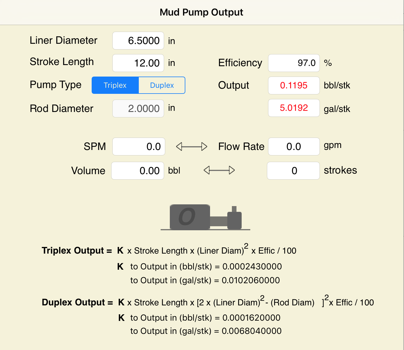
Oil and Gas drilling process - Pupm output for Triplex and Duplex pumpsTriplex Pump Formula 1 PO, bbl/stk = 0.000243 x ( in) E.xample: Determine the pump output, bbl/stk, at 100% efficiency for a 7" by 12". triplex pump: PO @ 100%,= 0.000243 x 7 x12 PO @ 100% = 0.142884bbl/stk Adjust the pump output for 95% efficiency: Decimal equivalent = 95 + 100 = 0.95 PO @ 95% = 0.142884bbl/stk x 0.95 PO @ 95% = 0.13574bbl/stk Formula 2 PO, gpm = [3(D x 0.7854)S]0.00411 x SPM where D = liner diameter, in. S = stroke length, in. SPM = strokes per minute Determine the pump output, gpm, for a 7" by 12". triplex pump at 80 strokes per minute: PO, gpm = [3(7 x 0.7854) 1210.00411 x 80 PO, gpm = 1385.4456 x 0.00411 x 80 PO = 455.5 gpm
Example:Duplex Pump Formula 1 0.000324 x (liner diameter, in) x ( stroke lengh, in) = ________ bbl/stk -0.000162 x (rod diameter, in) x ( stroke lengh, in) = ________ bbl/stk Pump out put @ 100% eff = ________bbl/stk Example: Determine the output, bbl/stk, of a 5 1/2" by 14" duplex pump at 100% efficiency. Rod diameter = 2.0": 0.000324 x 5.5 x 14 = 0.137214bbl/stk -0.000162 x 2.0 x 14 = 0.009072bbl/stk Pump output @ 100% eff. = 0.128142bbl/stk Adjust pump output for 85% efficiency: Decimal equivalent = 85 100 = 0.85 PO@85%)= 0.128142bbl/stk x 0.85 PO@ 85% = 0.10892bbl/stk Formula 2
PO. bbl/stk = 0.000162 x S[2(D) - d] where S = stroke length, in. D = liner diameter, in. d = rod diameter, in. Example: Determine the output, bbl/stk, of a 5 1/2". by 14". duplex pump @ 100% efficiency. Rod diameter = 2.0in.: PO@100%=0.000162 x 14 x [ 2 (5.5) - 2 ] PO @ 100%)= 0.000162 x 14 x 56.5 PO@ 100%)= 0.128142bbl/stk Adjust pump output for 85% efficiency: PO@85%,= 0.128142bb/stkx 0.85 PO@8.5%= 0.10892bbl/stk Metric calculation Pump output, liter/min = pump output. liter/stk x pump speed, spm. S.I. units calculation Pump output, m/min = pump output, liter/stk x pump speed, spm. Mud Pumps Mud pumps drive the mud around the drilling system. Depending on liner size availability they can be set up to provide high pressure and low flow rate, or low pressure and high flow rate. Analysis of the application and running the Drill Bits hydraulics program will indicate which liners to recommend. Finding the specification of the mud pumps allows flow rate to be calculated from pump stroke rate, SPM. Information requiredo Pump manufacturer o Number of pumps o Liner size and gallons per revolution Weight As a drill bit cutting structure wears more weight will be required to achieve the same RoP in a homogenous formation. PDC wear flats, worn inserts and worn milled tooth teeth will make the bit drill less efficiently. Increase weight in increments of 2,000lbs approx. In general, weight should be applied before excessive rotary speed so that the cutting structure maintains a significant depth of cut to stabilise the bit and prevent whirl. If downhole weight measurements are available they can be used in combination with surface measurements to gain a more accurate representation of what is happening in the well bore.

NOTE: Max RPM in the above equation varies according to type of pump, size of stroke, and other variables. Duplex pumps often run about 100 RPM Max. while triplex pumps will run somewhere between 100 RPM Max and 400 RPM Max.
I have a reciprocating pump and I know what my max rated rod load is (in foot pounds). I also know what size plunger size my pump has. What PSI will my pump produce?
Specific Gravity is used when sizing a centrifugal pump. Liquids with a specific gravity greater than 1.0 are heavier than water and conversely, liquids with a specific gravity lower than 1.0 are lighter weight than water and will generally float on water.

You can safely browse the pages, as the Mathcad server was separate to this main website, and was only accessible here. (We used something called an iFrame, which is like a window into a different website).
UPDATE 3rd of February 2020:We’ve been unable to recover the Mathcad worksheets and offer them in a format that provided total security to users. They were published a decade ago, and our IT people say that they would need a complete re-creation with the latest code and security fixes.
APPEAL:These 44 pages were created, and offered as a free resource for over a decade. We know from our website analytics that more than 1000 users visited each month. If only half of these regular visitors donated $20, we would have enough to create an even better solution. As you know, time is money, have these Mathcad pages saved you $20 in time over the years? We expect that they have, not to mention the learning opportunities provided to new engineers entering the industry.
YES! I’ve gotten value from the drillers Mathcad in the past, and a $20 is a very affordable way of saying thanks. I also want to preserve this tool for future engineers.
NO! I can’t or won’t donate to the restoration fund. I’m happy to spend a few minutes to offer a testimonial to help encourage the effort. These worksheets do have value. Offer Feedback.
The current release of this worksheet exists in different versions. They are identical apart from the way they are formatted. The Work version hides intermediate calculations and allows the user to see the results just below the inputs. The Audit version displays all intermediate calculations.
This worksheet takes inputs for the rig pumps and (optionally) hole and pipe sizes. It outputs pump flow rates and power, also fluid velocity if diameters entered.

Pumps tend to be one of the biggest energy consumers in industrial operations. Pump motors, specifically, require a lot of energy. For instance, a 2500 HP triplex pump used for frac jobs can consume almost 2000 kW of power, meaning a full day of fracking can cost several thousand dollars in energy costs alone!
So, naturally, operators should want to maximize energy efficiency to get the most for their money. Even a 1% improvement in efficiency can decrease annual pumping costs by tens of thousands of dollars. The payoff is worth the effort. And if you want to remotely control your pumps, you want to keep efficiency in mind.
In this post, we’ll point you in the right direction and discuss all things related to pump efficiency. We’ll conclude with several tips for how you can maintain pumping efficiency and keep your energy costs down as much as possible.
In simple terms, pump efficiency refers to the ratio of power out to power in. It’s the mechanical power input at the pump shaft, measured in horsepower (HP), compared to the hydraulic power of the liquid output, also measured in HP. For instance, if a pump requires 1000 HP to operate and produces 800 HP of hydraulic power, it would have an efficiency of 80%.
Remember: pumps have to be driven by something, i.e., an electric or diesel motor. True pump system efficiency needs to factor in the efficiency of both the motor AND the pump.
Consequently, we need to think about how electrical power (when using electric motors) or heat power (when using combustion engines) converts into liquid power to really understand pump efficiency.
Good pump efficiency depends, of course, on pump type and size. High-quality pumps that are well-maintained can achieve efficiencies of 90% or higher, while smaller pumps tend to be less efficient. In general, if you take good care of your pumps, you should be able to achieve 70-90% pump efficiency.
Motor efficiency is also an important factor here. Motor efficiency depends on the fuel type, whether electricity or hydrocarbon, which in turn depends on availability and cost.
AC motors can achieve 90%+ efficiency when converting electrical to mechanical energy. Combustion engines are much less efficient, with typical efficiency ratings coming in at ~20% for gasoline and ~40% for diesel. Your choice of engine or motor type will depend on the availability and cost of fuel or electricity in your area.
Electric motors are more efficient than combustion engines, but site location and the cost of fuel can make the choice of combustion engines more practical.
Now that we have a better understanding of the pump efficiency metric, let’s talk about how to calculate it. The mechanical power of the pump, or the input power, is a property of the pump itself and will be documented during the pump setup. The output power, or hydraulic power, is calculated as the liquid flow rate multiplied by the "total head" of the system.
Remember: we’re trying to find the ratio of power in to power out. Since rations require equal units on both sides, we"ll have to do some conversions to get our hydraulic power units in HP. You"ll see how this is done in the example below.
IMPORTANT: to calculate true head, you also need to factor in the work the pump does to move fluid from the source. For example, if the source water is below the pump, you need to account for the extra work the pump puts in to draw source water upwards.
*Note - this calculation assumes the pump inlet is not pressurized and that friction losses are minimal. If the pump experiences a non-zero suction pressure, or if there is significant friction caused by the distance or material of the pipe, these should be factored in as well.
Every foot of water creates an additional 0.434 PSI of pressure, so we"ll find the elevation head by converting the change in elevation in feet to the suction pressure created by the water.
You"ll notice that the elevation head is minimal compared to the discharge pressure, and has minimal effect on the efficiency of the pump. As the elevation change increases or the discharge pressure decreases, however, elevation change will have a greater impact on total head.
Obviously, that’s a fair amount of math to get at the pump efficiency, considering all of the units conversions that need to be done. To avoid doing these calculations manually, feel free to use our simple pump efficiency calculator.
Our calculations use static variables (pump-rated horsepower and water source elevation) and dynamic variables (discharge flow and pressure). To determine pump efficiency, we need to measure the static variables only once, unless they change.
If you want to measure the true efficiency of your pump, taking energy consumption into account, you could add an electrical meter. Your meter should consist of a current transducer and voltage monitor (if using DC) for electrical motors or a fuel gauge for combustion. This would give you a true understanding of how pump efficiency affects energy consumption, and ultimately your bank account.
Up until this point, we’ve covered the ins and outs of how to determine pump efficiency. We’re now ready for the exciting stuff - how to improve pump efficiency!
One of the easiest ways to improve pump efficiency is to actually monitor pumps for signs of efficiency loss! If you monitor flow rate and discharge (output power) along with motor current or fuel consumption, you’ll notice efficiency losses as soon as they occur. Simply having pump efficiency information on hand empowers you to take action.
Another way to increase efficiency is to keep pumps well-maintained. Efficiency losses mostly come from mechanical defects in pumps, e.g., friction, leakages, and component failures. You can mitigate these issues through regular maintenance that keeps parts in working order and reveals impending failures. Of course, if you are continuously monitoring your pumps for efficiency drops, you’ll know exactly when maintenance is due.
You can also improve pump efficiency by keeping pumps lubricated at all times. Lubrication is the enemy of friction, which is the enemy of efficiency (“the enemy of my enemy is my friend…”).
The best way to ensure lubrication is to monitor lube tanks or sumps and make sure you always have lubrication on hand. You can also monitor lubricant consumption for significant changes. If lubricant usage goes up, it could signal that friction has increased in the system.
A fourth way to enhance pump efficiency is to ensure your pumps and piping are sized properly for your infrastructure. Although we’re bringing this up last, it’s really the first step in any pumping operation. If your pumps and piping don’t match, no amount of lubricant or maintenance will help.
Pipes have physical limits to how much fluid they can move at a particular pressure. If pipes aren’t sized properly, you’ll lose efficiency because your motor will have to work harder. It’s like air conditioning - if your ductwork isn’t sized appropriately for your home, you’ll end up paying more on your energy bill.
In this post, we’ve given you the full rundown when it comes to calculating and improving pump efficiency. You can now calculate, measure, and improve pump efficiency, potentially saving your business thousands of dollars annually on energy costs.
For those just getting started with pump optimization, we offer purpose-built, prepackaged solutions that will have you monitoring pump efficiency in minutes, even in hazardous environments.

This website is using a security service to protect itself from online attacks. The action you just performed triggered the security solution. There are several actions that could trigger this block including submitting a certain word or phrase, a SQL command or malformed data.

The ratio of the actual output volume of a positive displacement pump divided by the theoretical geometric maximum volume of liquid that the pump could output under perfect conditions. Inefficiencies are caused by gaseous components (air and methane) being trapped in the liquid mud, leaking and noninstantaneously sealing valves in the pumps, fluid bypass of pump swab seals, and mechanical clearances and "play" in various bearings and connecting rods in the pumps. This efficiency is usually expressed as a percentage, and ranges from about 92% to 99% for most modern rig pumps and cement pumps. For critical calculations, this efficiency can be determined by a rigsite version of the "bucket and stopwatch" technique, whereby the rig crew will count the number of pump strokes required to pump a known volume of fluid. In cementing operations, displacement is often measured by alternating between two 10-bbl displacement tanks.

Pump OutputDuplex Pump OutputLitres/Stroke @ 90% Efficiency (2” Rod Diameter)Liner Diamerter (mm)StrokeLength(mm)101 108 114 121 127 133 140 146 152 159 165 170 178 184 190 197 203 209 216203 5.40 6.19 6.99 7.78 8.73 6.69 10.6 11.5 12.7 13.8 15 16.2 17.4 18.9254 6.67 7.62 8.58 6.69 10.8 12.0 13.3 14.6 15.9 17.3 18.7 20.0 21.9 23.6305 7.78 9.90 10.10 11.40 12.9 14.3 15.9 17.3 19.1 20.7 22.6 24.3 26.2 28.3 30.4356 14.6 16.4 18.0 19.9 21.8 23.8 25.9 28.0 30.2 32.4 35.0 37.4 39.9381 15.6 17.3 19.2 21.1 23.2 25.3 27.5 29.7 32.3 34.7 37.4 39.9 42.8406 16.7 18.6 20.5 22.6 24.8 27.0 29.4 32.3 34.5 37.0 39.7 42.8 45.6 48.6457 18.4 20.7 22.7 25.3 27.8 30.2 32.7 35.6 38.5 41.3 44.5 47.7 51.1 54.4508 20.3 22.7 25.1 28.0 30.5 33.4 36.4 39.4 46.2 45.9 49.4 53.1 56.8 60.4559 49.8 53.5 57.3 61.1 65.1 69.2 73.5610 71.1 75.6 80.2Note: For pump output in m 3 /stroke, move the decimal point 3 places to the left.Duplex Mud PumpsThe pistons on a duplex mud pump work in both directions, so that the rear cylinder has thepump rod moving through its swept volume and occupying some volume. The difference incalculations for a duplex vs. a triplex pump is that the displacement volume of this pump rodmust be subtracted from the volume in one of the cylinders, plus the difference in number ofpumping cylinders; 4 for a duplex and 3 for a triplex. Duplex pumps generally have longerstrokes (in the 10 to 18 in. range) and operate at lower rate; in the 40 to 80 stroke/minrange.The general equation to calculate output of a duplex pump is:Pump output (litres/stroke) = ,Where:ID = ID of the linerOD = OD of the rodL = Length of the pump strokeEff = Pump efficiency (decimal)1800, 505 – 3 rd Street SW Calgary, Alberta, Canada T2P 3E6 Telephone: 403.547.2906 Fax: 403.547.3129Email: info@hitechfluid.com Web: www.hitechfluid.com

The mud pump piston is a key part for providing mud circulation, but its sealing performance often fails under complex working conditions, which shorten its service life. Inspired by the ring segment structure of earthworms, the bionic striped structure on surfaces of the mud pump piston (BW-160) was designed and machined, and the sealing performances of the bionic striped piston and the standard piston were tested on a sealing performance testing bench. It was found the bionic striped structure efficiently enhanced the sealing performance of the mud pump piston, while the stripe depth and the angle between the stripes and lateral of the piston both significantly affected the sealing performance. The structure with a stripe depth of 2 mm and angle of 90° showed the best sealing performance, which was 90.79% higher than the standard piston. The sealing mechanism showed the striped structure increased the breadth and area of contact sealing between the piston and the cylinder liner. Meanwhile, the striped structure significantly intercepted the early leaked liquid and led to the refluxing rotation of the leaked liquid at the striped structure, reducing the leakage rate.
Mud pumps are key facilities to compress low-pressure mud into high-pressure mud and are widely used in industrial manufacture, geological exploration, and energy power owing to their generality [1–4]. Mud pumps are the most important power machinery of the hydraulic pond-digging set during reclamation [5] and are major facilities to transport dense mud during river dredging [6]. During oil drilling, mud pumps are the core of the drilling liquid circulation system and the drilling facilities, as they transport the drilling wash fluids (e.g., mud and water) downhole to wash the drills and discharge the drilling liquids [7–9]. The key part of a mud pump that ensures mud circulation is the piston [10, 11]. However, the sealing of the piston will fail very easily under complex and harsh working conditions, and consequently, the abrasive mud easily enters the kinematic pair of the cylinder liner, abrading the piston surfaces and reducing its service life and drilling efficiency. Thus, it is necessary to improve the contact sealing performance of the mud pump piston.
As reported, nonsmooth surface structures can improve the mechanical sealing performance, while structures with radial labyrinth-like or honeycomb-like surfaces can effectively enhance the performance of gap sealing [12–14]. The use of nonsmooth structures into the cylinder liner friction pair of the engine piston can effectively prolong the service life and improve work efficiency of the cylinder liner [15–17]. The application of nonsmooth grooved structures into the plunger can improve the performance of the sealing parts [18, 19]. The nonsmooth structures and sizes considerably affect the sealing performance [20]. Machining a groove-shaped multilevel structure on the magnetic pole would intercept the magnetic fluid step-by-step and slow down the passing velocity, thus generating the sealing effect [21–23]. Sealed structures with two levels or above have also been confirmed to protect the sealing parts from hard damage [24]. The sealing performance of the high-pressure centrifugal pump can be improved by adding groove structures onto the joint mouth circumference [25]. The convex, pitted, and grooved structures of dung beetles, lizards, and shells are responsible for the high wear-resistance, resistance reduction, and sealing performance [26–28]. Earthworms are endowed by wavy nonsmooth surface structures with high resistance reduction and wear-resistance ability [29]. The movement of earthworms in the living environment is very similar to the working mode of the mud pump piston. The groove-shaped bionic piston was designed, and the effects of groove breadth and groove spacing on the endurance and wear-resistance of the piston were investigated [30]. Thus, in this study, based on the nonsmooth surface of earthworms, we designed and processed a nonsmooth striped structure on the surface of the mud pump piston and tested the sealing performance and mechanism. This study offers a novel method for prolonging the service life of the mud pump piston from the perspective of piston sealing performance.
The BW-160 mud pump with long-range flow and pressure, small volume, low weight, and long-service life was used here. The dimensions and parameters of its piston are shown in Figure 1.
A striped structure was designed and processed on the contact surface between the piston cup and the cylinder liner. The striped structure was 5 mm away from the outermost part of the lip, which ensured the lip could contact effectively with the cylinder liner. Based on the structural dimensions of the piston cup, we designed a 2-stripe structure, and the very little stripe space affected the service life of the piston [30]. Thus, the stripe space of our bionic piston was set at 5 mm. According to the machining technology, two parameters of stripe depth h and the angle between the stripes and lateral of the piston α were selected (Figure 2).
A mud pump piston sealing performance test bench was designed and built (Figure 3). This bench mainly consisted of a compaction part and a dynamic detection part. The compaction part was mainly functioned to exert pressure, which was recorded by a pressure gauge, to the piston sealed cavity. This part was designed based on a vertical compaction method: after the tested piston and the sealing liquid were installed, the compaction piston was pushed to the cavity by revolving the handle. Moreover, the dynamic detection part monitored the real-time sealing situation and was designed based on the pressure difference method for quantifying the sealing performance. This part was compacted in advance to the initial pressure P0 (0.1 MPa). After compaction, the driving motor was opened, and the tested piston was pushed to drive the testing mud to reciprocate slowly. After 1 hour of running, the pressure P on the gauge was read, and the pressure difference was calculated as , which was used to measure the sealing performance of the piston.
To more actually simulate the working conditions of the mud pump, we prepared a mud mixture of water, bentonite (in accordance with API Spec 13A: viscometer dial reading at 600 r/min ≥ 30, yield point/plastic viscosity radio ≤ 3, filtrate volume ≤ 15.0 ml, and residue of diameter greater than 75 μm (mass fraction) ≤ 4.0%), and quartz sand (diameter 0.3–0.5 mm) under complete stirring, and its density was 1.306 g/cm³ and contained 2.13% sand.
The orthogonal experimental design method was used to study the effect of factors and the best combination of factor levels [31]. Stripe depth h and angle α were selected as the factors and were both set at three levels in the sealing performance tests (Table 1).
The test index was the percentage of sealing performance improvement β calculated aswhere and are the pressure differences after the runs with the standard and the bionic pistons, respectively ().
The sealing performance tests showed the striped structures all effectively enhanced the contact sealing between the piston and the cylinder liner. In particular, the increase of sealing performance relative to the standard piston minimized to 21.05% in the bionic striped piston with a stripe depth of 3 mm and angle of 45° and maximized to 90.79% in the bionic striped piston with the stripe depth of 2 mm and angle of 90°. Range analysis showed the sealing performance of pistons was affected by the stripe depth h and angle α, and these two parameters (h and α) have the same effect on the sealing performance.
Figure 4 shows the effects of stripe depth and angle on the sealing performance of mud pump pistons. Clearly, the stripe depth should be never too shallow or deep, while a larger angle would increase the sealing performance more (Figure 4).
Sealing validity tests were conducted to validate the sealing performance of the bionic striped pistons. It was observed whether the sealing liquid would leak at the tail of the cylinder liner, and the time of leakage was recorded. The standard piston and the most effective bionic piston were selected to compare their sealing performances.
Both the standard piston and the bionic striped piston leaked, which occurred after 84 and 249 minutes of operation, respectively (Figure 5). Figure 6 shows the pressures of the two pistons during testing. Clearly, the sealing pressure of the standard piston declined rapidly before the leakage, but that of the bionic piston decreased very slowly. After the leakage, the reading on the pressure gauge in the standard piston declined to 0 MPa within very short time, but that of the bionic piston decreased much more slowly.
The beginning time of leakage was inconsistent between the standard and bionic pistons (84 minutes vs. 249 minutes). In order to compare the leakage of these two pistons, the leaked liquid was collected when the piston started to leak. The volume of the leaked liquid was measured using a graduated cylinder every 5 minutes from the 84th minute and 249th minute, respectively (both considered as 0 minute), for 20 minutes. Figure 7 shows the leaked amounts of the standard piston and the bionic piston. Clearly, after the leakage and failure, the leaking speed and amount of the bionic piston were both smaller than those of the standard piston.
The piston lips and the cylinder liner were under interference contact, and their mutual extrusion was responsible for the lip sealing. Thus, a larger pressure between the piston lips and the cylinder liner reflects a higher lip sealing effect.
The bionic striped piston with the highest sealing performance (h = 2 mm, α = 90°) was selected for the sealing mechanism analysis and named as the bionic piston. The 3D point cloud data of standard piston were acquired by using a three-dimensional laser scanning system (UNIscan, Creaform Inc., Canada). Then, the standard piston model was established by the reverse engineering technique. The striped structure of the bionic piston was modeled on basis of the standard piston.4.1.1. Contact Pressure of Piston Surface
The standard piston and the bionic piston were numerically simulated using the academic version of ANSYS® Workbench V17.0. Hexahedral mesh generation method was used to divide the grid, and the size of grids was set as 2.5 mm. The piston grid division is shown in Figure 8, and the grid nodes and elements are shown in Table 3. The piston cup was made of rubber, which was a hyperelastic material. A two-parameter Mooney–Rivlin model was selected, with C10 = 2.5 MPa, C01 = 0.625 MPa, D1 = 0.3 MPa−1, and density = 1120 kg/m3 [32, 33]. The loads and contact conditions related to the piston of the mud pump were set. The surface pressure of the piston cup was set as 1.5 MPa, and the displacement of the piston along the axial direction was set as 30 mm. The two end faces of the cylinder liner were set as “fixed support,” and the piston and cylinder liner were under the frictional interfacial contact, with the friction coefficient of 0.2.
Figure 9 shows the pressure clouds of the standard piston and the bionic piston. Since the simulation model was completely symmetrical and the pressures at the same position of each piston were almost the same, three nodes were selected at the lip edge of each piston for pressure measurement, and the average of three measurements was used as the lip edge pressure of each piston. The mutual extrusion between piston and cylinder liner happened at the lip, and thereby the larger of the lip pressure was, the better the sealing performance was. The lip pressure of the standard piston was smaller than that of the bionic piston (2.7371 ± 0.016 MPa vs. 3.0846 ± 0.0382 MPa), indicating the striped structure enhanced the mutual extrusion between the bionic piston and the cylinder liner and thereby improved the sealing performance between the lips and the cylinder liner. As a result, sand could not easily enter the piston-cylinder liner frictional interface, which reduced the reciprocated movement of sand and thereby avoided damage to the piston and the cylinder liner.
Figure 10 shows the surface pressures from the lip mouth to the root in the standard piston and the bionic piston. The surface pressure of the bionic piston surpasses that of the standard piston, and the pressure at the edge of each striped structure changes suddenly: the pressures at the striped structure of the bionic piston are far larger than at other parts. These results suggest the contact pressure between the edges of the striped structures and the cylinder liner is larger, and the four edges of the two striped structures are equivalent to a four-grade sealed lip mouth formed between the piston and the cylinder liner, which generates a multilevel sealing effect and thereby largely enhances the sealing effect of the piston.
The piston surface flow field was numerically simulated using the CFX module of the software ANSYS® Workbench V17.0. The side of the lips was set as fluid inlet, and the other side as fluid outlet, as shown in Figure 11. The inlet and outlet were set as opening models, and the external pressure difference between them was 0 Pa. The moving direction of the piston was opposite to the fluid flow direction. The fluid region was divided into grids of 0.2 mm, while the striped structures were refined to grade 2.
Figures 12 and 13 show the surface streamline clouds and sectional streamline clouds of the two pistons at the early stage of leakage when the fluid entered the interface. Clearly, compared with the standard piston, when the surface-leaked liquid from the bionic piston passed the striped structure, the streamlines were sparse and significantly decreased in number, and the flow velocity declined more. The flow velocity decreased from 0.9348 m/s to 0.7555 m/s in the bionic piston and from 0.9346 m/s to 0.9262 m/s in the standard piston. It shows that, after the blockage by the striped structures, the striped structure more significantly intercepted the leaked liquid and could reduce the leakage rate of the piston, thereby enhancing the sealing effect.
Figure 13 shows the section leakage streamline of the standard piston and the bionic piston. Clearly, compared with the standard piston, when the leaked liquid of the bionic piston flowed through the striped structures, the streamlines would reflux and reverse inside the striped structures, indicating the striped structures can efficiently store the leaked liquid and slow down the leakage.
To better validate the sealing mechanism of the bionic striped pistons, a piston’s performance testing platform was independently built and the sealed contact of the pistons was observed. A transparent toughened glass cylinder liner was designed and machined. The inner diameter and the assembly dimensions of the cylinder liner were set according to the standard BW-160 mud pump cylinder liners. The sealing contact surfaces of the pistons were observed and recorded using a video recorder camera.
Figure 14 shows the surface contact of the standard piston and the bionic piston. Clearly, in the contact areas between the standard piston and the cylinder liner, only the narrow zone at the lip mouth contacted, as the contact width was only 4.06 mm. On the contrary, the contact areas between the bionic piston and the cylinder liner were all very wide, as the contact width was about 18.36 mm, and the sealed area was largely enlarged (892.8 mm2 vs. 4037.6 mm2) according to the contact areas calculated, which were favorable for improving the sealing performance.
Figure 15 shows the oil film left after the piston running. The oil film width of the bionic piston was far larger than that of the standard piston (20.48 mm vs. 2.28 mm). The striped structure of the bionic piston could store the lubricating oils, and uniform oil films were formed after its repeated movement, which reduced the friction between the piston and the cylinder liner, so that the seal failure of the piston would not happen due to excessive abrasion.
(1)The bionic striped structure significantly enhanced the sealing performance of the mud pump pistons. The stripe depth and the angle between the stripes and the piston were two important factors affecting the sealing performance of the BW-160 mud pump pistons. The sealing performance was enhanced the most when the stripe depth was 2 mm and the angle was 90°.(2)The bionic striped structure can effectively enhance the contact pressure at the piston lips, enlarge the mutual extrusion between the piston and the cylinder liner, reduce the damage to the piston and cylinder liner caused by the repeated movement of sands, and alleviate the abrasion of abrasive grains between the piston and the cylinder liner, thereby largely improving the sealing performance.(3)The bionic striped structure significantly intercepted the leaked liquid, reduced the leakage rate of pistons, and effectively stored the leaked liquid, thereby reducing leakage and improving the sealing performance.(4)The bionic striped structure led to deformation of the piston, enlarged the width and area of the sealed contact, the stored lubricating oils, and formed uniform oil films after repeated movement, which improved the lubrication conditions and the sealing performance.
The bionic striped structure can improve the sealing performance and prolong the service life of pistons. We would study the pump resistance in order to investigate whether the bionic striped structure could decrease the wear of the piston surface.

You can safely browse the pages, as the Mathcad server was separate to this main website, and was only accessible here. (We used something called an iFrame, which is like a window into a different website).
UPDATE 3rd of February 2020:We’ve been unable to recover the Mathcad worksheets and offer them in a format that provided total security to users. They were published a decade ago, and our IT people say that they would need a complete re-creation with the latest code and security fixes.
APPEAL:These 44 pages were created, and offered as a free resource for over a decade. We know from our website analytics that more than 1000 users visited each month. If only half of these regular visitors donated $20, we would have enough to create an even better solution. As you know, time is money, have these Mathcad pages saved you $20 in time over the years? We expect that they have, not to mention the learning opportunities provided to new engineers entering the industry.
YES! I’ve gotten value from the drillers Mathcad in the past, and a $20 is a very affordable way of saying thanks. I also want to preserve this tool for future engineers.
NO! I can’t or won’t donate to the restoration fund. I’m happy to spend a few minutes to offer a testimonial to help encourage the effort. These worksheets do have value. Offer Feedback.
The current release of this worksheet exists in different versions. They are identical apart from the way they are formatted. The Work version hides intermediate calculations and allows the user to see the results just below the inputs. The Audit version displays all intermediate calculations.
This worksheet takes inputs for the rig pumps and (optionally) hole and pipe sizes. It outputs pump flow rates and power, also fluid velocity if diameters entered.

Browse through more than 1,500 duplex piston rods and 200 duplex pony rods in our inventory. EC Tool gives you a quote before your order, so you know what you’re getting for your money every time. While we primarily keep connecting rods for GA550 and GA750 models in stock, there are other options at your disposal as well. This includes custom connecting rods for most duplex and triplex mud pumps.
We now offer new crossheads and capsules for both EMSCO D-375 and DB-550 duplex pumps. You can also find slides and shoes for certain models. Available parts currently in our inventory include:
We carry a large inventory of valve cap plugs made for OEM and MATTCO fluid ends. You’ll also find different drop-in plugs for most gland-type valve caps.

Electronic Pump Stroke Counters are a vital part to any drilling rig operation. When a mud pump is in operation, the driller must know how much mud is flowing down hole in order to keep the operation running at peak efficiency. Pump stroke counters assist the driller by measuring the mud pump’s strokes per minute and total strokes. So, how does a pump stroke counter tally the mud pump’s strokes
Electronic Pump Stroke Counters are a vital part to any drilling rig operation. When a mud pump is in operation, the driller must know how much mud is flowing down hole in order to keep the operation running at peak efficiency. Pump stroke counters assist the driller by measuring the mud pump’s strokes per minute and total strokes. So, how does a pump stroke counter tally the mud pump’s strokes, and why it is important? In order to understand that, you’ll need to know some basic information about mud pumps.
Knowing how a mud pump functions is important in understanding the role a pump stroke counter plays in rig operations. Mud pumps act as the heart of the drilling rig, similar to how our heart works. Just as our heart circulates blood throughout our bodies, a mud pump circulates essential drilling mud down the hole and back up to the surface. Mud tanks house drilling mud, and a mud pump draws the fluid from the mud pump. A piston draws mud in on the backstroke through the open intake valve and pushes mud through the discharge valve and sends it towards the rig. By circulating fluid, the mud pump ensures that the drill bit is cool and lubricated and that cuttings are flushed from the hole. The two main kinds of pumps used are duplex and triplex pumps, where the duplex pump has two pistons and the triplex pump has three. Whether the rig is using a duplex or triplex pump, it is important to know how many strokes per second the pistons are moving. The driller monitors strokes per minute to determine how much costly, yet essential, mud is being pumped into the system with the use of a mud pump stroke counter system. Now, that you know about mud pumps, you’ll need to know what’s in a stroke counter system.
Stroke Counter — The stroke counter stainless steel box is mounted on the driller’s console and is either square or rectangular in shape, depending on the number of pumps it is monitoring. Stroke counters will show strokes per minute and total strokes, and when a particular mud pump is operating the strokes/minute and total strokes will be displayed. Power is supplied by a 3.6 volt lithium battery, and the counter contains a crystal-controlled real time clock with 100 parts per million accuracy or better. Each counter is mounted to the console with 1/4” stainless steel hex head bolts, lock washers and nuts.
Micro Limit Switch — The micro switch is connected to a c clamp near the mud pump piston. The micro switch stainless steel rod (sometimes called a whisker) sticks out in the piston housing near the piston. As the piston passes the rod, it moves the rod and the switch sends an electronic signal back to the counter. The counter increases by one each time the piston moves the rod, counting the mud pump’s strokes. The switch’s signal is then transmitted to the stroke counter. These micro switches are built to stand up to demanding outdoor conditions. They can withstand shock, equipment vibration, extreme temperatures, water and dust.
Cable and Junction Box – A cable is connected to the back of the pump stroke counter and then to the junction box. From the junction box, the cables travel to the limit switches.
Pump Stroke Counters are like a blood pressure machine. Each time our heart pumps, a blood pressure machine reads our systolic and diastolic blood pressure by way of our pulse. A mud pump stroke counter functions in much the same way. Just as a blood pressure machine detects our pulse so too does a limit switch rod detect the movement of the piston. When the stainless steel rod is moved, the micro limit switch detects the movement. The signal is sensed as a contact closure, and it is transmitted to the stroke counter where the contact closure is converted to a logic pulse. The pulse feeds two separate circuits. The total strokes circuit reads and displays the closures one at a time, totaling them up to reveal the total strokes in the LED window. The second pulse is sent along a separate circuit which is a rate circuit. This rate circuit will average the closures against the real time clock. The result is displayed as the total strokes per minute.
Pump stroke counters are essential to drilling rig operations because they measure the efficiency of mud pumps. Knowing strokes per minute and total strokes of the pistons helps the driller to determine if the correct amount of mud is going down hole. Having this information aids in running a drilling rig at peak efficiency, assists in extending drill bit life, and avoids costly overuse of drilling rig mud. Unsure which pump stroke counter is right for your application? Give our friendly, knowledgeable staff a call or email. We’ll keep you turning right.


 8613371530291