
how to install bomco mud pump crosshead quotation

This website is using a security service to protect itself from online attacks. The action you just performed triggered the security solution. There are several actions that could trigger this block including submitting a certain word or phrase, a SQL command or malformed data.

We specialize in complete Bomco restoration of internal wear parts Offering thermal spray coatings and specialty welding processes OD & IS Grinding & Machining To OEM Size.
Periodically we"ll inspect for wear, cracks and damage to critical components such as bearings, bull gear and pinion, conrods and crossheads. We"ll check the condition of your seals and other rubber goods and look for oil contamination. We"ll inspect your frame and ensure your pump is set up as per the manufacturer"s recommended tolerances, providing feedback and detailed reporting.
Bomco parts including the fluid end, power end, stuffing boxes, plungers, seals, bearings, diesel engines, and natural gas engines. We also have blasting and painting facilities as well as a machine shop. We have many years of experience rebuilding mud pumps
Where Bomco overhaul is required we"ll take care of complete disassembly, cleaning and NDT. Repairs will be made to machined components as necessary. Bearings, seals and other components will be replaced in line with our inspections. Motors will be overhauled, lube systems serviced and pulsation dampeners recertified. We"ll also check your fluid ends are in spec and can repair or replace. Your pump is then fully reassembled and commissioned.

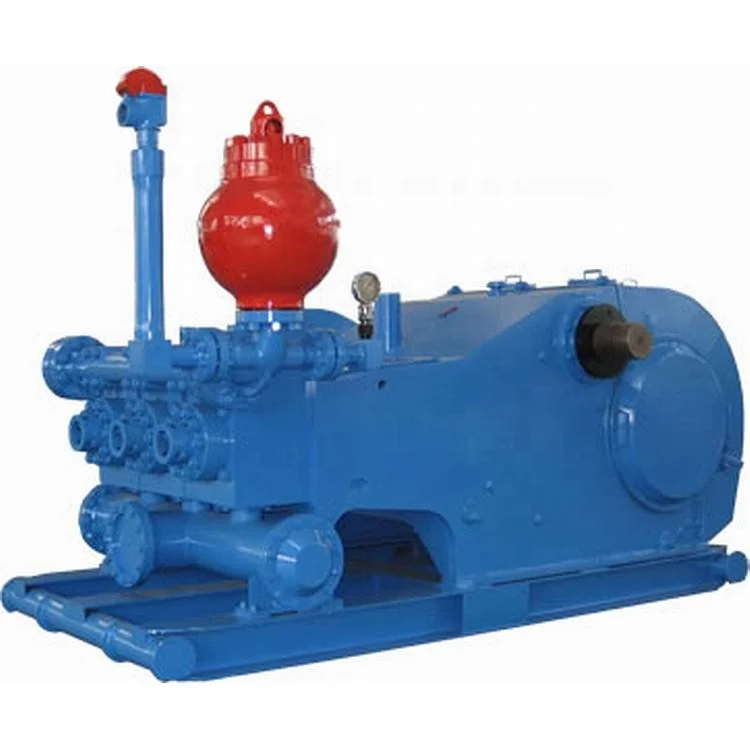
Thanks for using F series mud pumps produced by Baoji Oilfield Machinery Co., Ltd. The outline dimension, frame, and fluid end of F-1300 and 1600 mud pump are the same, only the bearing and gear pair of power end are different. For convenience of customer, this manual introduces these two kinds mud pumps at the same time.
(3.206) Note: 1. Based on 100% volumetric efficiency and 90% mechanical efficiency. Recommended strokes and input power for continuous service. Table 1B Performance data of F-1300/1600 Mud Pump Liner Diameter, in & Rating pressure, MPa(Psi) 6 3/4 6 1/2 6 1/4...
Fig. 2 1.2.1. Ground Installation When ground installation is going on, 8 pieces of 76mm×305mm boards is cushioned in the direction of pump skid, as indicated in Fig.2. The base of boards should be 300mm wider than that of pump skid beam.
Fig. 3 1.2.3. Installations of Driving Device The drive between the mud pumps and prime mover should be adopted V-belts or multi-row chains drive, which is installed with precision to assure longest service life and minimum possibility of unexpected or undesirable shutdowns due to drive failures. When installing the drive sheave or sprocket, make sure all grease or rust preventative is removed clearly from the shaft end and the matched bore.
Stationary spray pipes have been used on F-series pumps Ref. Fig 5. It consists of a fixture frame (1), steel pipe (2) and spray nozzle (3), it makes cooling fluid spray to piston and liner. Adjust cooling water supply to the manifold and inspect spray nozzle operation very often to make sure the nozzle is pointed directly at the piston.
Instruction Manual for F1300/1600 Mud Pump 1.6.2. Liners Installs wear-resisting plate seal (1) in counter bore of fluid end (see Fig. 8). Install wear-resisting plate (2) through studs until it seats against fluid end. Mount liner flange (3) over studs with the starting thread at the 5 o’clock position and tighten bolts with 640~690N.m (470~510ft.lbs) torque.
Instruction Manual for F1300/1600 Mud Pump 1.6.6. Valve Cover Install valve cover seal ring (18) into bore, and after grease the valve cover seal area and threads area, tighten the valve covers into place using a sledge hammer and bar. 1.6.7 Discharge Manifold API 5"...
Instruction Manual for F1300/1600 Mud Pump shield ○ 8 is used for lifting dampener assembly. Before assembly thoroughly clean ring groove, gasket ring ○ 1 and groove of mating flange and coat with grease. Lifting the dampener to the corresponding position of mud pump discharge line, screw nut (R4) with 950~1265N.m (700~935ft.lbs) torque.
Instruction Manual for F1300/1600 Mud Pump Fig.15 (1) Filter (2) Oil distributor (3) Oil line (3A) Spray nozzle (4) Main bearing oil line (4A) Oil distributor (5)Pressure gauge (6) Relief valve (7) Oil trough (8) Oil tube (9) Lubrication pump A pressure relief valve (6) is mounted to the oil distributor (2) to prevent excess pressure from damaging oil pump and drive.
Instruction Manual for F1300/1600 Mud Pump Fig.18 (1) Cover (2) Bolt (3) Retainer ring (4) Bolt (5) Bearing retainer ring (7) Retainer ring (8) Bolt (8A) Inner hex bolts (9) Main bearing (10) Right bearing sleeve (11) Left bearing sleeve (12) Outer retainer ring (13) Connecting rod bearing (14) Inner retainer ring (15) Bolt (16) Main bearing retainer (17) Inner race retainer (18) Bolt (19) Crosshead bearing 1) Install gear ring and check run-out.
Instruction Manual for F1300/1600 Mud Pump valve spring, change the damaged one. Check if the locknuts of piston are corrosive or damaged. Change if they are Weekly damaged (normally, change after using three times). Weekly Check the filter screen of lubricating system. Clean it if it is plugged. Weekly Loosen the plug of drain flange, discharge the dirt and water in the oil pool.
Instruction Manual for F1300/1600 Mud Pump become sealed off and the air gets charging piping or change the discharge reduces or no mud into the pump. gasket. discharged. 2. The suction filter screen is 2. Stop the pump and clean the plugged.
Instruction Manual for F1300/1600 Mud Pump F-1300/1600 Spare Parts List F-1300/1600 Tool List F-1300/1600 Mud Pump General Assembly 11 43 54 6 56 17 8 36 B向...
Instruction Manual for F1300/1600 Mud Pump F-1300/1600 Drilling Mud Pump Drawing No. Item Description F-1300 F-1600 Frame assembly AH1301020100 AH1301020100 Crank shaft assembly AH1301020200 AH1601020100 Pinion shaft assembly AH1301020300 AH1601020200 Crosshead assembly AH1301020400 AH1301020400 Fluid end assembly AH1301020500 AH1301020500 Power...
Instruction Manual for F1300/1600 Mud Pump Drawing No. Item Description F-1300 F-1600 Flange T508-1002 T508-1002 KB-75 Dampener AK75350200 AK75350200 JA-3 Shear relieve valve AH0000060200 AH0000060200 Connection tube T510-1002 T510-1002 Cover plate AH1301011800 AH1301011800 Right-angle joint T511-1002 T511-1002 Bolt 1/2-13UNCX1 T500-1001...
Instruction Manual for F1300/1600 Mud Pump Crankshaft Assembly Fluid End 13 14 Drawing No. Item Description F-1300 F-1600 Main bearing AH130101020100 AH130101020100 cover Bearing sleeve, AH1301010202 AH1601020101 right Gasket AH1301010203 AH1301010203 Inner race AH1301010204 AH1301010204 retainer Outer race AH130101020500 AH160101010200...
Instruction Manual for F1300/1600 Mud Pump Drawing No. Item Description F-1300 F-1600 AH130101020100 AH130101020100 Locating ring (I) AH1301020201 AH1601020101 Hollow crankshaft AH1301010203 AH1301010203 Locating ring (II) AH1301010204 AH1301010204 Gear ring AH130101020500 AH160101010200 Piston 1/2-8UN Bolt 1 1/2-8UNx5 AH1301020202 AH1601020102 AH1301020203...
Instruction Manual for F1300/1600 Mud Pump Drawing No. Item Description F-1300 F-1600 AH1301010218 AH1601010108 Gear ring (split one) 420501036160200000 420501036160200000 Bolt 1 1/2-8UN× F-1300/1600 Pinion Shaft Assembly 11 16 Fluid End Drawing No. Item Description F-1300 F-1600 AH1301020301 AH1301020301 Key 2″×2″×11 3/8″ AH1301020302 AH1601020201...
Instruction Manual for F1300/1600 Mud Pump Drawing No. Item Description F-1300 F-1600 T500-1027 T500-1027 Bolt 7/8-9UNCX2 AH1301010311 AH1301010311 seal 9.125"X10.375"X0.625" AH1301010312 AH1301010312 Bearing 4G32844H 420503011221600000 420503011221600000 Spring washer 22 (GB93) 420503011141600000 420503011141600000 Spring washer 14 (GB93) AH1301010313 AH1301010313 Flange T500-2003...
Instruction Manual for F1300/1600 Mud Pump F-1300/1600 Crosshead Assembly 30 20 Link 2426 Item No. Qty. Description Drawing No. Crosshead AH1301020401 Crosshead guide (upper) AH1301010402 Shim set AH100101041700 Shim AH1301010403 Stuffing box AH1301010404 Sealing ring AH1301010405 O-ring φ190×3.55 (GB3452.1) 530301011900035507...
Instruction Manual for F1300/1600 Mud Pump Item No. Qty. Description Drawing No. Double lip seal 5"X6.25"X0.625" AH1301010406 Locking spring AH1301010407 Mud guard plate AH1301010408 Crosshead extension rod AH1301010409 Crosshead pin AH1301020403 O-ring φ125×7 (GB3452.1) 530301011250070007 Bolt 3/4-10UNCX2 1/2 T500-3010 Plate gasket AH1301010411 O-ring φ160×7 (GB3452.1) 530301011600070007...
Instruction Manual for F1300/1600 Mud Pump Item Qty. Description Drawing No. AH130101052300 Shim set AH1001010527 Gasket 39 AH1001010510 Valve rod guide T500-7002 Stud bolt 1 1/2-8UNCX10 1/2 T501-2001 Nut 1 1/2-8UN AH1001010512 Retainer AH0501020509 Bolt 3/8-16UNCX3/4 530301010412035507 O-ring 41.2x3.55 (GB3452.1) T501-303.0 Piston nut 1 1/2-8UN 530301011850070007...
Instruction Manual for F1300/1600 Mud Pump Item Description Drawing No. Key 3/16×3/16×1 T516-2001 Oil pump gear assembly AH080102060100 90° elbow NPT1/4×NPT 3/8 T001-2204 Bolt A12(GB5650) 520902540320120100 Inner hexagon screw 5/16-18UNCX1 T500-3003 Connector A16 (JB/ZQ4410) 520901010350040040 Connector A8 (JB/ZQ4410) 520901010350050050 90° elbow NPT1/4×NPT1/4 T001-2203 Copper tube 051102010080010002...
Instruction Manual for F1300/1600 Mud Pump Item Description Drawing No. Washer A12 (GB5651) 520902551280120100 Bolt 1/4-20UNCX3/4 T500-1007 Oil jet AH1301010601 Copper tube Φ12×610 (GB1527) 051102010012010002 Copper tube Φ8×813 (GB1527) 051102010080010002 Connector A8 (GB5628.1) 520901010050050050 Pipe clamp-double Φ8 AH050102060200 051102010010010002 Copper tube Φ10×1956 (GB1527)...
Instruction Manual for F1300/1600 Mud Pump AH130102080100 Guard AH130102080300 Sheave AH1301010802 Support Assembly AH100102080200 Connector Z1″-G1″ AH1001010804 Connector Z1″ AH1001010805 Connector G1″-M33×2 AH1001010806 Connector ZG2-1/2″ AH1001010807 Connector ZG2 1/2″-Z2 1/2 AH1001010808 Hose Φ22×Φ37 140501010220100000 Hose connector Φ22×Φ37 AH100101080900 Elbow 90° Z1" AH1001010810 Connection plate AH1001020803...
Instruction Manual for F1300/1600 Mud Pump F-1300/1600 Suction Dampener Item No. Description Drawing No. Suction dampener assembly AH0000050100 Bladder AH0000050101 Cover AH0000050102...
Instruction Manual for F1300/1600 Mud Pump F-1300/1600 Discharge Strainer Assembly Item Description Part No. O-ring φ165×7 530301011650070007 Strainer Assembly AH100101190200 Housing AH1001011901 Stud M39×2-M39×3×135 T503-4007 Nut M39×3 T507-2011 Flange 5 1/8×35MPa T508-1002 Gasket ring R44 T508-5002 Discharge cross joint AH100101200300...
KB-75 Pulsation Dampener Item Description Drawing No. General drawing AK75350200 Gasket ring R39 T508-5001 Bottom plug AK75350101 Bladder AK7535010200 Housing assembly AK7535020100 Cover AK75350202 Tee joint NPT 1/4″ T511-2001 Joint NPT 1/4″ AK75350106 Pressure gauge guard assembly AK7535020300 Air discharge valve AK7535010001 Pressure gauge 0-25MPa NPT1/4 380202052250006020...
Instruction Manual for F1300/1600 Mud Pump Gasket T514-1001 Stud bolt 1 1/2X4 3/4 T500-6002 Nut 1 1/2-8UN T501-2001 Stud nut 1 1/4X4 1/4 T500-6003 Nut 1 1/4-8UN T500-2002 Pulsation Dampener Charging Hose Assembly Item Description Drawing No. Pulsation dampener charging AH100102130100 hose assembly Nut G5/8″...
Instruction Manual for F1300/1600 Mud Pump Screw M4×16 420101021104001600 Bolt T500-1016 3/8-16UNCX4 1/4 T501-1005 3/8-16UNC Screw M3×8 420101020703000800...
Instruction Manual for F1300/1600 Mud Pump F-1300/1600 Tool List Item No. Description Drawing No. Attachment tools AH1301021000 Liner lifting tool AH130102100100 Cylinder head rod AH100101210100 Sleeve 2 3/8″ AH1001012108 Sleeve 2″ AH1001012109 Sleeve 3 5/8″ AH1301011602 Sleeve 1 1/2″ AH1301011603...
A wide variety of bomco f1000 mud pump options are available to you, such as 1 year, not available.You can also choose from new, bomco f1000 mud pump,As well as from energy & mining, construction works , and machinery repair shops. and whether bomco f1000 mud pump is 1.5 years, 6 months, or unavailable.

Whether onshore or offshore, well drilling sites rely on a multitude of systems to successfully perform the drilling operation. The mud pump is a key component tasked with circulating drilling fluid under high pressure downhole. The mud pump can be divided into two key sections: the power end or crosshead and the fluid end. Proper alignment of the pump’s crosshead to the fluid end liner is necessary to maximizing piston and liner life. Misalignment contributes to
accelerated wear on both the piston and the liner, and replacing these components requires downtime of the pump. Traditional methods of inspecting alignment range from using uncalibrated wooden rods, Faro Arms and micrometers to check the vertical and horizontal alignment of the piston rod OD to the piston liner ID. These are time consuming and cumbersome techniques that are ultimately not well suited to troubleshoot and solve alignment issues.
A “Mud Pump Laser Alignment Kit” enables you to measure where the piston will run through the liner at various positions along the pump’s stroke. It will also project a laser centerline from the fluid end back towards the rear power end of the pump that can be used to determine how much shimming is required to correct any alignment issues. The kit can include either a 2-Axis receiver or a 4-Axis which accepts the laser beam and documents where it falls on the active surface of the receiver. The 4-Axis receiver can decrease alignment time by as much as 50% as it will measure angularity as well as X and Y while the 2-Axis does not and will need multiple measurement locations to get the same information. In addition, the alignment system is a non-intrusive service requiring the removal of only the piston rod which allows for much quicker service and less down time on the pump. As the mud pumps in question are located globally both on and offshore, having a small, portable system is another great advantage. Our recommendation would be Pinpoint laser System’s “Mud Pump Alignment Kit”. They are being used by many of the leading repair service companies and have been their main alignment tool for over 15 years. Manufacturers are also utilizing these for new pump set-up.

Important Buyers Notice: All items are Sold"As-Is" with "No Warranty" expressed or implied. Items offered for sale may be damaged, inoperable and/or missing parts. You are strongly urged to carefully review each photo and video as well as personally inspect the item before making a decision to purchase. Free Oilfield Quote is not responsible for any missing or damaged equipment, part, item or accessory and shall not be held liable for any damage prior to or during the removal and/or delivery of the equipment. Any and all agreements contrary to the above disclaimer must be in writing and agreed upon up front and prior to any transaction.

This website is using a security service to protect itself from online attacks. The action you just performed triggered the security solution. There are several actions that could trigger this block including submitting a certain word or phrase, a SQL command or malformed data.

This website is using a security service to protect itself from online attacks. The action you just performed triggered the security solution. There are several actions that could trigger this block including submitting a certain word or phrase, a SQL command or malformed data.

Important Buyers Notice: All items are Sold"As-Is" with "No Warranty" expressed or implied. Items offered for sale may be damaged, inoperable and/or missing parts. You are strongly urged to carefully review each photo and video as well as personally inspect the item before making a decision to purchase. Free Oilfield Quote is not responsible for any missing or damaged equipment, part, item or accessory and shall not be held liable for any damage prior to or during the removal and/or delivery of the equipment. Any and all agreements contrary to the above disclaimer must be in writing and agreed upon up front and prior to any transaction.
2.Any unusual conditions of the cooling system should be avoided. Such as: if spray pump packing leaks; if spray pipe is bent or blocked; if water stream of spray nozzle sprays to 12 o’clock direction of the top of ceramic liner inner surface; if water flow is adequate, etc. If there is any unusual conditions, examination and maintenance should be carried out without delay.
2) Loosen threaded ring by 1-2 threads, use pipe tongs to bite top end of liner and rotate liner (if it’s hard to rotate, please add a torsion bar to the handle of pipe tongs), then fasten threaded ring.
6.Mud should be released out from mud pump when drilling job finished in winter and the temperature is lower than 0 centigrade degrees. And before restart the pump, the ice from liner and piston surface need to be cleaned in case the ice will scratch the liner and piston working surface.
7.Frequently check guide plate, pony rod, piston rod, cross head, piston and clamp, if there is any rusting or deformed,needed to be changed or repaired in time. And please be noted that the piston definitely cannot be eccentric or eccentric wear.
As a reminder: the outer diameter of piston core is 1.8 - 2.2mm smaller than that of the ceramic liner inner diameter. Meanwhile, the piston core end is designed to be in inverted arc angle to reduce the resistance of cooling water.


 8613371530291