
how to use a drywall mud pump factory
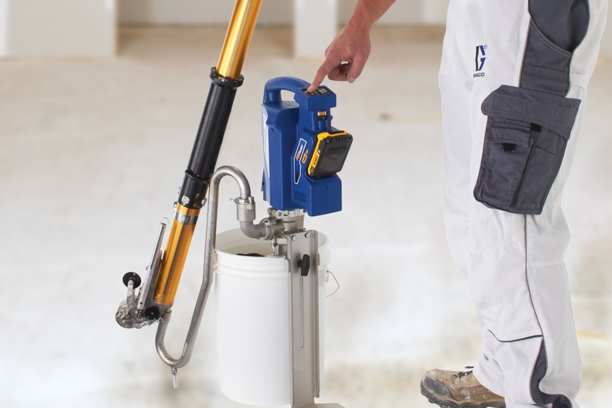
Drywall mud pumps are essential if you are going to use automatic taping tools. Typical drywall pumps are simple lever action pumps that sit in a five-gallon bucket of mud. They have about a three-inch tube that reaches to within a couple of inches of the bottom of the bucket and sucks drywall mud from the bottom.
The spout on these pumps is approximately 5/8" in diameter and located at the base of the lever which sits near the top of the five-gallon bucket. The spouts also come with a small metal tube flattened on one end that serves as an adapter to fill taping boxes. You can also attach a gooseneck to the spout which allows you to fill a drywall bazooka with drywall mud.
Drywall pumps should never be used with hot mud, or quick set drywall mud. Quick set drywall mud hardens by means of a chemical process, therefore it can easily harden inside of the pump before you have a chance to clean it out.
There are pneumatic drywall pumps on the market as well. They are usually sold in conjunction with specific tools. For example, the "Apla Tech" taping system is centered around a pneumatic pump system.
There are not many reasons to invest in a drywall pump if you plan on using no more than basic taping tools like pans and knives. However, if you choose to invest in automatic taping tools including flat boxes, angle boxes, a bazooka, the mud runner or any of these types of tools, you will need to make sure you have a reliable drywall pump.

When it comes to drywall tools, a compound pump is a workhorse that keeps all drywall finishing and taping tools moving. So, what makes a good drywall pump? Here"s LEVEL5 founder Scott Murray with an overview (or read on to learn more).
LEVEL5’s drywall compound pump has been made to meet finisher’s demand forreliability, affordability and workability. This beast of a taping tool is built to withstand years of heavy use.
We specifically chose to construct our pump out of billet aluminum (instead of less-durable cast aluminum) to give it as rock-solid a build as possible. Using advanced anodization technology, we’ve designed our compound pump to feature outstanding corrosion resistance. This same anodization also makes it more resistant to everyday wear and tear.
The body of the LEVEL5 mud pump is longer to make it compatible with more bucket sizes. Its composite cup seal is designed to be longer lasting than traditional rubber seals used by other major brands. To effectively minimize pump priming we"ve added a precision-molded flapper valve and seal assembly.
The build quality, attention to innovation and 7-Year warranty make this pumpunrivaled in terms of value to the finisher. Combine these with the fact that LEVEL5’s compound pump is among the most affordable on the market and it’s easy to see why our taping tools are setting the industry standard for finishers far and wide.
This drywall mud pump has been built to last, comes ready to go right out of the box and is innovated to fit any drywall finisher’s workflow. We’ve gone above and beyond to make our pump the most workable on the market.
No doubt the ability to clean, repair and maintain your drywall tools plays a big role in which taping tools you choose to invest in. We’ve built the LEVEL5 drywall pump to be extremely easy to take apart and rebuild thanks to heavy-duty grenade pins and easy-release latches on its tube and handle.
To help make tool maintenance second nature, we’ve created a built-in wrench mount to ensure quick access to your wrench that comes included with every purchase of a LEVEL5 drywall compound pump. Once you’ve mastered how to take apart and maintain your pump, you’ll never be without one on the job.
To help ensure that your LEVEL5 mud pump is ready to go right out of the box, we include afreebox filler valvewith every purchase. This filler valve is quickly and easily swapped out with our gooseneck so that you can go from filling flat boxes to filling your automatic taper seamlessly.
It’s important to note that the LEVEL5 drywall compound pump is not compatible with goosenecks from other manufacturers due to the pump’s extended length. The LEVEL5 Gooseneck (4-714) has been specifically designed for use with this pump.
Here at LEVEL5 we know you want a pump that’s dependable, affordable and easy to maintain. Our pump’s innovative design features, premium build materials and 7-Year warranty provide unsurpassed value to the finisher.
{"links":[{"url":"https://www.graco.com/us/en/contractor/solutions/articles/how-to-mix-drywall-mud-for-texture-spraying.html", "anchor_text":"How to Mix Drywall Mud for Texture Spraying"},{"url":"https://www.graco.com/us/en/contractor/products/drywall-finishing-interior-texture/interior-texture-sprayers.html", "anchor_text":"Interior Texture Sprayers"},{"url":"https://www.graco.com/us/en/contractor/products/drywall-finishing-interior-texture/drywall-finishing-tools-accessories.html", "anchor_text":"Drywall Finishing Tools & Accessories"}]}

This Invention relates to tools used to install and finish drywall in buildings and to hand pumps for pumping viscous fluids. BACKGROUND OF THE INVENTION
Drywall, also known as gypsum board, wallboard, and plasterboard, is a building material used to finish the interior surfaces of walls and ceilings in houses and other buildings. Rigid sheets or panels of drywall are formed from gypsum plaster, the semi-hydrous form of calcium sulphate (CaSO4.½× H2O), which is typically sandwiched between two layers of heavy paper or fiberglass mats. Drywall sheets are about ½ inch thick and are nailed or screwed in place to form the interior surfaces of the building, and provide fire resistance and sound deadening, among other benefits.
The joints between drywall sheets are typically filled and sealed with strips of paper or fiberglass mat and drywall joint compound, also called “joint compound”, “drywall mud”, or just “mud”. Joint compound may be made, for example, of water, limestone, expanded perlite, ethylene-vinyl acetate polymer and attapulgite. Joint compound is applied as a viscous fluid that is thick enough to maintain its shape while it hardens. In addition to forming joints, drywall mud is used to cover nail or screw heads, form a smooth or flat surface, and provide a texture over the surface. Paint or wall paper is typically applied over the drywall and joint compound.
Workers often specialize in the installation of drywall, and in large projects different crews install the drywall panels (drywall hangers) from those who finish the joints and apply the joint compound (tapers or mudmen). Workers who specialize in drywall installation often use specialized tools to increase their productivity including flat boxes that are tools used to hold joint compound and apply it to drywall joints. Joint compound is often mixed (e.g., with water) or stored in buckets, and drywall mud pumps have been used to pump the mud from the buckets into flat boxes or other tools or containers.
U.S. patent application Ser. No. 11/292,238, publication 2007/0122301 (also by Werner Schlecht) describes a drywall mud pump. However, it was found that in operation pumping drywall joint compound that friction developed within the pump making it difficult to use. Thus, needs or potential for benefit exist for drywall mud pumps that have less internal friction. In addition, needs and potential for benefit exist for drywall mud pumps that are inexpensive to manufacture, reliable, easy to use, that have a long life, that are easy to service and clean, and that are simple in operation so that typical operators can effectively maintain them. Room for improvement exists over the prior art in these and other areas that may be apparent to a person of ordinary skill in the art having studied this document. Summary of Particular Embodiments of the Invention
This invention provides, among other things, certain drywall mud (drywall joint compound) pumps with particular features or capabilities. Various embodiments provide, as objects or benefits, for example, that they have less internal friction than certain prior art pumps. In addition, particular embodiments provide, for instance, as objects or benefits, drywall mud pumps that are inexpensive to manufacture, reliable, easy to use, that have a long life, that are easy to service and clean, that are simple in operation, or a combination thereof. Other benefits of certain embodiments may be apparent to a person of ordinary skill in the art.
In specific embodiments, this invention provides certain drywall mud pumps that include a main cylinder and a rod having two ends, a first end and a second end. In many embodiments, when the drywall mud pump is assembled, the second end of the rod is located within the main cylinder, for example. Various embodiments also include a piston which, when the drywall mud pump is assembled, is also located within the main cylinder and is attached to the second end of the rod. In some embodiments, there is a connection structure between the piston and the second end of the rod, which is configured to allow the second end of the rod to move relative to the piston in a direction that is substantially perpendicular to the axis of the rod. A number of embodiments include a means for allowing the second end of the rod to move laterally relative to the piston within the main cylinder. Further, in some embodiments the piston specifically includes an elongated hole that receives the second end of the rod, and the elongated hole allows the second end of the rod to move laterally relative to the piston.
Various such embodiments further include a pump head, which may have an output aperture, and when the drywall mud pump is assembled, the pump head may be connected to the main cylinder and the rod may pass through the pump head. In some embodiments, the drywall mud pump further includes a handle and a linkage, and when the drywall mud pump is assembled, the handle may be pivotably connected to the first end of the rod, and the linkage may be pivotably connected to the pump head and pivotably connected to the handle, as examples. Moreover, some embodiments may include (e.g., in the pump head) a means for guiding the rod, a means for allowing the rod to pivot as the second end of the rod moves laterally relative to the piston, or both. Further, particular embodiments include a guide having a hole through which the rod slidably passes. Some embodiments include just one guide in the pump head, which may serve as both a guide and as a pivot point for the rod, and in some embodiments, the guide may be shortened to provide for pivoting.
In a number of embodiments, the piston includes an elastomeric piston cup having a first hole, which may be elongated, a top rigid support having a second elongated hole, a bottom rigid support having a third elongated hole, and a flapper having a fourth elongated hole. In some embodiments, when the drywall mud pump is assembled, the second end of the rod passes through each of the first, second, third, and fourth holes, for example. Further, certain embodiments include a means for preventing the piston from rotating about the rod. In some embodiments, as an example, the second end of the rod has a flattened portion, at least the second and third elongated holes are substantially the same size and have substantially the same shape, and, when the drywall mud pump is assembled, are held in a particular orientation by the flattened portion of the second end of the rod.
Even further, in some embodiments, when the drywall mud pump is assembled, the second end of the rod is attached to the piston with a nut (e.g., a lock nut), an elongated washer, or both. Moreover, in some embodiments, the piston cup, the top rigid support, and the bottom rigid support each have at least one passageway therethrough for passage of the drywall mud, and when the drywall mud pump is assembled, the flapper covers the (at least one) passageway substantially blocking passage of the drywall mud when the piston is moving in the main cylinder toward the pump head.
In various embodiments, the piston cup, the top rigid support, and the bottom rigid support each have multiple passageways therethrough for passage of the drywall mud, and the multiple passageways substantially surround the first, second, and third elongated holes. In addition, in some such embodiments, a plurality of the multiple passageways for passage of the drywall mud have at least one curved side and at least one straight side. Additionally, in particular embodiments wherein an elongated washer is provided, when the drywall mud pump is assembled, the washer substantially blocks the elongated hole in the piston to prevent drywall mud from passing through the elongated hole in the piston. In a number of such embodiments, the drywall mud pump may also include a means for controlling the rotational position of the washer.
Further, in some embodiments, the second end of the rod includes a first reduced diameter flattened section and a second reduced diameter flattened section. In some such embodiments, for example, the second reduced diameter flattened section has a smaller diameter, thickness between flats, or both, than the first reduced diameter flattened section. Further, in some embodiments, the second end of the rod also includes a threaded section. Further still, in some embodiments, when the drywall mud pump is assembled, the second end of the rod passes through each of the first, second, third, and fourth elongated holes such that the fourth elongated hole is located at the first reduced diameter flattened section, and the first, second and third elongated holes are located at the second reduced diameter flattened section. In addition, various other embodiments of the invention are also described herein. BRIEF DESCRIPTION OF THE DRAWINGS
FIG. 7 is an isometric exploded view of the piston, rod, and pump head of the example of a mud pump of the previous figures, except that the piston in FIG. 7 is not shown exploded;
The drawings illustrate, among other things, a particular example of an embodiment of the invention, and various examples of characteristics thereof. Different embodiments of the invention include various combinations of elements shown in the drawings, described herein, known in the art, or a combination thereof. DETAILED DESCRIPTION OF EXAMPLES OF EMBODIMENTS
FIG. 1 illustrates an example of an assembled drywall mud pump, pump 10. Parts and features that are visible from the outside in this view include output aperture 11 in pump head 14 where drywall mud emerges from pump 10 when handle 12 is moved, for example, by an operator of drywall mud pump 10. In some embodiments, a detachable high filler (not shown) may attach to aperture 11 (e.g., with the nuts 11 nshown) and may extend the location where the mud emerges to a higher elevation to enhance ergonomics. FIG. 2 is an exploded view of the same embodiment of drywall mud pump 10 shown in FIG. 1.
In the embodiment illustrated, rod 13 passes through pump head 14 (visible in FIG. 1 through aperture 11) into main cylinder 15. Pump head 14 is mounted on or connected to main cylinder 15, in this embodiment, with clips 25. Also in this embodiment, handle 12 is pivotably connected to the top or first end 21 of rod 13 with pin 23, and linkage 16 is pivotably connected at the top (of linkage 16) to handle 12 and at the bottom (of handle 16) to pump head 14 with bolts 26.
Other visible parts of pump 10 include foot plate 18, which is connected to pump head 14 with bolts 28, in this embodiment, and foot valve 19, which is connected to the bottom end of cylinder 15 with pin 29.
When in use, main cylinder 15 may extend into a bucket of drywall joint compound or mud while foot plate 18 may extend outside of the bucket to the floor. The operator may place his foot on foot plate 18 to steady pump 10 while moving handle 12. Foot valve 19, in the bottom of the bucket, may form or include a check valve that may allow mud to flow upward into cylinder 15, but may substantially prevent mud from flowing downward out of cylinder 15 through foot valve 19. Rod 13 also passes through shortened guide 17, in this embodiment, and guide 17 is attached to pump head 14 with bolts 27. Thus, guide 17 is easily removable and replaceable.
FIG. 2 also introduces piston 20, which, in this embodiment, includes several different components that will be discussed in more detail with reference to other figures. In this embodiment, when drywall mud pump 10 is assembled, piston 20 is located within main cylinder 15 and is attached to the bottom or second end 22 of rod 13. In addition, when drywall mud pump 10 is assembled, second end 22 of rod 13 is also located within main cylinder 15. When an operator pushes handle 12 down, piston 20 goes up toward pump head 14, pushing drywall mud that is in cylinder 15 out through aperture 11. During this process, a vacuum is created below piston 20, which draws more drywall mud into cylinder 15 through foot valve 19. When the operator pulls handle 12 up, piston 20 goes down, away from pump head 14, foot valve 19 prevents the drywall mud below piston 20 from exiting cylinder 15 through the bottom, and drywall mud flows through piston 20, as will be described in more detail below.
During the operation of mud pump 10, horizontal or lateral forces are exerted on rod 13. Even if the operator only exerts vertical forces on handle 12, since linkage 16 is not vertical during most of the stroke of piston 20, linkage 16 exerts lateral forces on handle 12, which are carried by handle 12 to rod 13. These horizontal or lateral forces on rod 13 are believed to cause increased friction or binding within prior art drywall mud pumps. In a number of embodiments, drywall mud pump 10, and various other drywall mud pumps in accordance with this invention, allow rod 13 to move laterally without binding (or with reduced binding) and in a manner that reduces friction (e.g., within mud pump 10). In different embodiments, such a reduction in friction makes the drywall mud pump (e.g., 10) easier to use. In addition, in many embodiments, reduced friction reduces wear, thus increasing pump life, maintaining a level of pump performance for a longer time, reducing the need for replacement of parts, reducing the need for servicing of the pump, or the like.
FIG. 3 is a closer view of assembled piston 20 attached to second end 22 of rod 13. FIG. 4 is an exploded view of piston 20 and rod 13, and shows the components of piston 20 and details of second end 22 of rod 13, in the embodiment illustrated. In this embodiment, piston 20 includes nut 41, elongated washer 42, bottom wiper support 43, piston seal, wiper, or cup 44, top wiper support 45, and flapper 46. In some embodiments, a means may be provided for preventing nut 41 from turning or loosening once nut 41 is installed. In many embodiments, for example, nut 41 is a lock nut (e.g., having a nylon insert), but in other embodiments, nut 41 may be a regular (hexagonal) machine nut. In some embodiments, nut 41, piston 20, or rod 13 may include a cotter key, set screw, jam nut, lock washer, or the like, to prevent nut 41 from turning once installed. Further, in other embodiments, a bolt, machine screw, snap ring, other fastener, or the like, may be provided instead of nut 41.
In a number of embodiments, piston cup 44 may be an elastomeric material such as rubber or a synthetic equivalent thereof. Other components shown in FIGS. 3 and 4 may be metal, such as steel, stainless steel, brass, bronze, aluminum, or the like, or may be made of a plastic, a polymer, or nylon, for example. In the embodiment illustrated, piston cup 44 has an outside diameter that is slightly larger than the inside diameter of main cylinder 15. Thus, an interference fit may exist between piston cup 44 and main cylinder 15, and when piston 20 is inside main cylinder 15 (e.g., when drywall mud pump 10 is assembled), the outside diameter of piston cup 44 may contact the inside surface of main cylinder 15.
Bottom wiper support 43, in this embodiment, has an outside diameter that is less than the outside diameter of piston cup 44, and slightly less than the inside diameter of main cylinder 15. Bottom wiper support 43 may be rigid, may provide support to piston cup 44, and may have a clearance fit with main cylinder 15. Top wiper support 45, in this embodiment, has an outside diameter that is less than the outside diameter of piston cup 44, less than the inside diameter of main cylinder 15, and may have an outside diameter that is less than (or equal to) the outside diameter of bottom wiper support 43. Top wiper support 45 may also be rigid, and may also provide support to piston cup 44. As used herein, components of piston 20 are said to be rigid if the material that the components are made of has a stiffness (i.e., modulus of elasticity) that is at least twice that of the material that piston cup 44 is made of.
Flapper 46, in this embodiment, has an outside diameter that is less than the outside diameter of piston cup 44, less than the inside diameter of main cylinder 15, and may be less than the outside diameter of bottom wiper support 43, top wiper support 45, or both. In this embodiment, Flapper 46 has a diameter that is sufficiently small to allow drywall mud to flow between flapper 46 and the inside surface of main cylinder 15, for example, when piston 20 is traveling downward (e.g., away from pump head 14). In the embodiment illustrated, flapper 46 is rigid. In other embodiments, flapper 46 may be flexible. In some embodiments, flapper 46 (or an alternative flapper) may bend or pivot out of the way of the flow of drywall mud when piston 20 is traveling downward, for example. In some embodiments, a flapper or component analogous to flapper 46 may be made of two or more pieces, which may be different materials and may have different stiffnesses.
In a number of embodiments, piston 20 includes an (e.g., at least one) elongated hole that receives second end 22 of rod 13. Such an elongated hole may allow second end 22 of rod 13 to move laterally relative to piston 20, for example. As used herein, “laterally” means in a direction that is substantially perpendicular to the longitudinal axis of rod 13. As used herein, “substantially perpendicular”, unless stated otherwise, means 90 degrees, plus or minus 30 degrees, and “perpendicular” (without being preceded by “substantially”), unless stated otherwise, means 90 degrees, plus or minus 5 degrees.
In the embodiment illustrated, piston cup 44 of piston 20 has a first elongated hole 44 h, top support 45 has a second elongated hole 45 h, bottom support 43 has a third elongated hole 43 h, and flapper 46 has a fourth elongated hole 46 h. In the embodiment shown, when drywall mud pump 10 is assembled, second end 22 of rod 13 passes through each of the first, second, third, and fourth elongated holes (i.e., 43 h, 44 h, 45 h, and 46 h). Further, the embodiment illustrated includes a means for preventing piston 20 from rotating about rod 13. Specifically, in the embodiment illustrated, second end 22 of rod 13 has first and second flattened portions 49 and 48, which, in this embodiment, each have a reduced diameter from the remainder of rod 13. In this embodiment, the second and third elongated holes (i.e., holes 45 hand 43 hin top and bottom supports 45 and 43) are substantially the same size and have substantially same shape, and, when drywall mud pump 10 is assembled, are held in a particular orientation by second flattened portion 48 of second end 22 of rod 13.
As used herein, “substantially the same”, when referring to a dimension, unless stated otherwise, means the same to within 10 percent. In addition, as used herein “held in a particular orientation” when referring to a piston or part of a piston, means that the piston or part is prevented from rotating about the longitudinal axis of the rod by more than 45 degrees. In some embodiments, first hole 44 hmay also have substantially the same size and shape as holes 43 hand 45 h. In other embodiments, first hole 44 hmay have a different shape. In certain embodiments, for example, first hole 44 h, or a corresponding hole in the piston cup, may be round, may be larger than third hole 43 hor second hole 45 h, or both. Further, in a number of embodiments, different components of the piston (e.g., components 43-46 of piston 20) may have elongated holes, while in other embodiments, an elongated hole may appear only in one component of the piston, or in one of the top and bottom supports, for example, to hold the piston in a particular orientation with a flattened portion of the second end of the rod. In some embodiments, for example, the third hole 43 hin bottom support 43 may be round, may be larger than the second hole 45 hin top support 45, or both, and in other embodiments, second hole 45 hmay be round, may be larger than third hole 43 h, or both.
In the embodiment illustrated, second reduced diameter flattened section 48 has a smaller diameter and thickness between flats than first reduced diameter flattened section 49. Other embodiments may have different sections that just have different diameters or different thicknesses between flats. Further, in the embodiment shown, second end 22 of rod 13 also includes threaded section 47, which in this embodiment, receives nut 41. Further still, when drywall mud pump 10 is assembled, second end 22 of rod 13 passes through each of first, second, third, and fourth elongated holes 43 h-46 hsuch that fourth elongated hole 46 his located at first reduced diameter flattened section 49, and first, second and third elongated holes 43 h-45 hare located at second reduced diameter flattened section 48.
In the embodiment illustrated, second end 22 of rod 13 has two reduced diameter flattened portions 48 and 49. In other embodiments, just one flattened portion may be provided, or 3 or more distinct flattened portions may be provided, as examples. Also, in the embodiment illustrated, the flattened portions (e.g., 48 and 49) and the elongated holes 43 h, 44 h, 45 h, and 46 hhave round or rounded ends. Other embodiments may have square ends (e.g., a rectangular cross section) or another shape.
In the embodiment shown, flattened portion 49 has a sufficient dimension in the axial direction (i.e., of the longitudinal axis of rod 13) to allow flapper 46 to move away from top support 45 when piston 20 is traveling downward away from pump head 14. This allows room for the drywall mud to flow outward between flapper 46 and top support 45 before flowing around the outside of flapper 46. When piston 20 travels in upward, toward pump head 14, flapper 46 moves in the axial direction to the other end of flattened portion 49 until flapper 46 makes contact with top support 45.
In some embodiments, there is a connection structure between the piston (e.g., 20) and second end (e.g., 22) of the rod (e.g., 13) that is configured to allow the second end (e.g., 22) of the rod (e.g., 13) to move relative to the piston (e.g., 20) in a direction that is substantially perpendicular to the axis of the rod (e.g., rod 13). The elongated hole or holes (e.g., 43 h, 44 h, 45 h, 46 h, or a combination thereof) through which second end 22 of rod 13 passes, is an example of such a connection structure. Further, a number of embodiments, including the embodiment illustrated, include a means for allowing the second end (e.g., 22) of the rod (e.g., 13) to move laterally relative to the piston (e.g., 20) within the main cylinder (e.g., 15). Other embodiments, besides what is shown in the drawings, may differ in geometry. For example, some embodiments may use a slot or hole in the rod, a pin, a track, a linkage, or the like.
As used herein, a means for allowing an end of a rod to move laterally relative to a piston does not include motion resulting from prior art magnitude clearance between the rod and the piston in a drywall mud pump, movement resulting from deformation of an elastomeric piston cup, or deformation of the rod or other components resulting from stress imposed thereon. Rather, a means for allowing an end of a rod to move laterally relative to a piston requires a structure that provides for substantially more lateral movement of the rod under substantially less force than prior art mud pump technology provided. In this context, as used herein, “substantially” means by a factor of at least two.
In different embodiments, the second end 22 of rod 13 may be able to move laterally relative to piston 20 by at least or about 1/16, ⅛, 3/16, ¼, 5/16, ⅜, 7/16, ½, 9/16, ⅝, ¼, ⅞, 1, 1 ⅛, 1 ¼, or 1 ½, inch, or 2 inches, for example, under lateral forces normally present within such a drywall mud pump. In the embodiment illustrated, the elongated hole (e.g., 43 h) in piston 20 is centered within piston 20. But in other embodiments, the elongated hole may extend from the center of piston 20 in one direction, or may extend farther on one side of center than the other, as examples.
In the embodiment illustrated, nut 41 does not clamp down on bottom support 43, piston cup 44, and top support 45. Rather, sufficient clearance is left between nut 41 and support 43, piston cup 44, and top support 45 to allow them to move freely in the lateral direction across elongated holes 43 h-45 h. The axial dimension of flattened portion 48 may be sized accordingly. In some embodiments, where nut 41 is a lock nut, for example, nut 41 may be turned until the correct amount of clearance is obtained. In other embodiments, nut 41 may be tightened against the end of threaded portion 47, as another example.
FIG. 5 is a detailed view of the same embodiment of bottom support 43. Bottom support 43 includes elongated hole 43 hwhich has round ends (i.e., part of a circle). Bottom support 43 includes round holes 51 which receive projections 44 p(shown in FIG. 4) of piston cup 44. Projections 44 pmay have an interference fit with holes 51, in this embodiment, and may help to hold piston cup 44 in place (e.g., held in the appropriate particular orientation) relative to bottom support 43. In the embodiment shown, bottom support 43 also includes tabs 52 which also help to hold piston cup 44, top support 45, or both in place (e.g., held in the appropriate particular orientation) relative to bottom support 43. The embodiment illustrated includes four tabs 52, although only one of tabs 52 is labeled with a reference number, the one that is the most visible from the perspective of FIG. 5.
Bottom support 43 also includes multiple passageways 53, 54, 55, and 56 therethrough for passage of drywall mud. These passageways 53, 54, 55, and 56 substantially surround (third) elongated hole 43 h. As shown in FIG. 4, in the embodiment illustrated, corresponding passageways having substantially the same shape extend through piston cup 44 and top support 45 and substantially surround (first and second) holes 44 hand 45 h, as well. Drywall mud flows through these passageways (e.g., 53-56), between top support 45 and flapper 46, and around the outside of flapper 46 (i.e., between flapper 46 and the inside of main cylinder 15) when piston 20 is moving downward (i.e., away from pump head 14).
Still referring to FIG. 5, in the embodiment illustrated, all four of the multiple passageways 53, 54, 55, and 56 for passage of drywall mud have at least one curved side 57 and at least one straight side 58, as labeled, for example, for passageway 56. In the embodiment illustrated, the shape of passageways 53, 54, 55, and 56 provides for essentially as much area for the flow of drywall mud therethrough as possible, while maintaining adequate structural strength of the components (e.g., bottom support 43, piston cup 44, etc.).
As mentioned, when piston 20 is traveling upward (i.e., toward pump head 14) in cylinder 15, flapper 46 makes contact with top support 45, blocking or substantially blocking passageways 53, 54, 55, and 56, thus preventing significant quantities of the drywall mud from flowing back through passageways 53, 54, 55, and 56. As used herein, in the context of blocking the flow of drywall mud, “substantially blocking” means blocking more than 90 percent of the cross sectional area (e.g., of passageways 53, 54, 55, and 56), and “blocking” (i.e., without being preceded by “substantially”) means blocking more than 99 percent of the cross sectional area (e.g., of passageways 53, 54, 55, and 56). Blocking or substantially blocking of passageways 53, 54, 55, and 56, in the embodiment illustrated, causes the drywall mud within cylinder 15 to exit through pump head 14 and orifice 11 when piston 20 travels upward (i.e., toward pump head 14).
Further, as shown for example in FIG. 3, in the embodiment illustrated, when drywall mud pump 10 is assembled, washer 42 blocks or substantially blocks the elongated hole (e.g., 43 h, 44 h, 45 h, and 46 h) in piston 20 to prevent drywall mud from passing through the elongated hole in piston 20 (e.g., when piston 20 is moving upward toward pump head 14). In a number of such embodiments, the drywall mud pump (e.g., 10), piston (e.g., 20), or rod (e.g., 13) may also include a means for controlling the orientation or rotational position (i.e., about the longitudinal axis of rod 13) of the washer (e.g., 42). This may facilitate washer 42 blocking or substantially blocking the elongated hole (e.g., 43 h).
In the embodiment illustrated, projections 59 of bottom support 43 control the rotational position of washer 42, and align washer 42 with elongated hole 43 hto block or substantially block hole 43 h. Elongated holes 44 h, 45 h, and 46 h, in this embodiment, line up with hole 43 h, and are also blocked by washer 42. In other embodiments, elongated washer 42 may be attached to or integral with nut 41 (e.g., a lock nut or with another means to prevent nut 41 from rotating on its own accord) or may have a tab that bends against a flat of nut 41, as examples. In other embodiments, washer 42 may be guided by a track, grove, projection, indentation, spline(s), or the like on bottom support 43, nut 41, or portions 47 or 48 of end 22 of rod 13, as examples. Further, in the embodiment illustrated, hole 42 hin elongated washer 42 is round, but in other embodiments, hole 42 hmay be elongated and may fit over a flattened section (e.g., section 48 of rod 13), or washer 42 may have a tab or projection that may fit into a slot in second end 22 of rod 13 to limit or prevent rotation of washer 42, as other examples. In other embodiments, hole 42 hmay be square, splined, hexagonal, octagonal, star shaped, or the like, and second end 22 of rod 13 may have a corresponding or mating shape. In another embodiment, hole 42 hof washer 42 is threaded and nut 41 locks against washer 42 to prevent washer 42 from rotating relative to rod 13, as another example.
FIG. 6 illustrates piston 20, rod 13, pump head 14, and shortened guide 17, all assembled. In this view, flapper 46 is shown against upper guide 45 (not visible) blocking or substantially blocking passageways 53, 54, 55, and 56, as would be the case when piston 20 is moving toward pump head 14. FIG. 7 shows these same components of drywall mud pump 10 in an exploded view, except that piston 20 is not separated into components or separated from rod 13. FIG. 7 shows, among other things, that below guide 17 is a wiper or rod seal 77, which may be made of an elastomeric material or synthetic rubber, for example, and may serve to prevent or substantially prevent drywall mud from within main cylinder or pump head 14 from traveling up along rod 13 through guide 17. Rod seal 77 may have a U-shaped cross section, for example, with the opening of the U pointed downward (i.e., toward piston 20). In other embodiments, rod seal 77 may have a cross section that is square, rectangular, triangular, trapezoidal, a parallelogram, or round, as examples, and may be solid or hollow.
FIGS. 8 and 9 illustrate more detail of the example of guide 17 of the embodiment illustrated. Guide 17, in this embodiment, includes hole 80h through which rod 13 passes when drywall mud pump 10 is assembled. Some embodiments may include (e.g., in pump head 14) a means for guiding rod 13, a means for allowing rod 13 to pivot (e.g., without binding) as second end 22 of rod 13 moves laterally relative to piston 20, or both. In the embodiment illustrated, guide 17 is a shortened guide, and rod 13 slidably passes through hole 80 hwhen pump 10 is assembled. Prior art guides for drywall mud pumps typically have a gland nut with a dimension 90 t(shown in FIG. 9) in the direction of the longitudinal axis of rod 13 that is ¾ inch or more. In the embodiment illustrated, guide 17 has a dimension 90 tof 0.300 inches. Other embodiments may have a dimension 90 tthat is more than ⅛, 3/16, or ¼ inch, and less than ½, ⅜ or 5/16 inch, or the like, as examples. As used herein, a “shortened guide” has a dimension 90 tthat is less than ½ inch.
Prior art gland nuts, which served as guides, typically included a recess within the gland nut for a bushing or liner that provided a sliding surface for the rod. This liner often consisted of a non-metal, such as nylon. Shortened guide 17, in the embodiment illustrated, however, does not include a recess for a bushing or liner, and in fact, no such liner is used in the embodiment shown. Rather, rod 13 slides directly on guide 17. Other embodiments may include a bushing or liner within a guide or gland nut, but may provide another means for allowing the rod to pivot (e.g., without binding) as the (second) end of the rod moves laterally relative to the piston. In some embodiments, for example, a bushing or liner may be provided that is made of or includes nylon, PTFE, or the like. In some embodiments in which the gland nut or guide is not shortened, for example, the guide may have a larger diameter or an elongated hole (e.g., 80h) therethrough. In other embodiments, a structure may be provided to allow the guide to pivot, as another example.
In some embodiments, guide 17 serves both as a guide and as a pivot point for rod 13. In some such embodiments, the outside diameter of rod 13 and the inside diameter of hole 80 hare selected to provide sufficient clearance between rod 13 and hole 80 hto allow second end 22 of rod 13 to move laterally over, for instance, the full range of the elongated hole (e.g., 43 h, 44 h, 45 h, 46 h, or a combination thereof) in piston 20 without causing binding between rod 13 and hole 80 h, for example, within guide 17. Further, in the prior art, upper and lower guides were used at the top and bottom of the pump head (e.g., otherwise similar to pump head 14). This provided little opportunity for the rod (e.g., similar to rod 13) to pivot in the pump head, and (as used herein) no means for allowing the rod to pivot as the second end of the rod moves laterally relative to the piston. In the embodiment shown, only one (i.e., a single) guide (17) is provided, and guide 17 is shortened, which (as used herein), if sized or shaped in certain ways, may provide a means for allowing rod 13 to pivot without binding as second end 22 of rod 13 moves laterally relative to piston 20.
In some embodiments, hole 80 hmay be round or a circular cylinder (e.g., a right circular cylinder), such as a drilled hole. In other embodiments, hole 80 hmay be elongated to allow rod 13 to pivot. In some embodiments, in particular, hole 80 hmay be round at one location (e.g., at the top or bottom surface of guide 17, or at a location therebetween) and elongated elsewhere, or may be elongated throughout, but the amount of elongation may vary. For example, in a number of embodiments, the elongation may become more pronounced further from the location where hole 80 his round, or further from a location where the elongation is a minimum. In some embodiments, for example, hole 80 his round or only slightly elongated at the bottom of guide 17, adjacent to seal 77, and maximum elongation occurs at the top of guide 17.
In some embodiments, hole 80 his manufactured as a right circular cylinder (e.g., a drilled hole), but quickly “wears in” when in use, to a shape that is elongated, for instance, with the most pronounced elongation at the top or bottom surface (or both) of guide 17. In some such embodiments, guide 17 is made of a relatively soft material, such as brass, and rod 13 is made of a harder material, such as stainless steel, which may be grade 420 stainless steel, and may be hardened to 35 Rockwell C (HRC), for example. In particular embodiments, rod 13 has an outside diameter of 0.626±0.005 inches, and hole 80 hin guide 17 has an inside diameter of 0.640±0.003 inches, for instance. In various such embodiments, friction in the operation of pump 10 may be greater when pump 10 is new, but may decrease once guide 17 wears in and binding between guide 17 and rod 13 declines or ceases. Such a shortened guide 17 that is configured to “wear in” to a shape that does not bind against rod 13, as used herein, is another example of a means for allowing rod 13 to pivot as second end 22 of rod 13 moves laterally relative to piston 20.
In the embodiment illustrated, once guide 17 wears in, and binding between guide 17 and rod 13 declines or ceases, the rate at which guide 17 wears may decrease substantially. However, in cases of frequent use of pump 10, guide 17 may continue to wear over time with continued use. At some point, guide 17 may be replaced. In the embodiment shown, guide 17 and seal 77 are easily replaceable by removing pin 23 and bolts 27.
In the embodiment illustrated, rod 13 has a round cross section, but in other embodiments, a corresponding rod may have a square, rectangular, hexagonal, octagonal, or other cross section. The round cross section illustrated may facilitate seal 77 shown in FIG. 7, although other cross section rods can be sealed adequately. In different embodiments, such a rod (e.g., 13) may be solid or hollow.
Drywall Master Taping Tools Extended Quick Clean Mud Pump is used to fill automatic taping tools with mud compound. DrywallMaster pump uses gooseneck (sold separately) to fill automatic taper. Box filler (also sold separately) attaches to pump to fill all other finishing tools. Industry exclusive double o-ring head seal on Drywall Master mud pump keeps mud from seeping between head and pump tube for better seal and easier separating, cleaning or maintenance.
Unique dual o-ring head seal keeps mud from getting between head casting and pump tube. This makes pump easier to separate for cleaning or maintenance.
The Loading Pump, with appropriate accessories (Gooseneck and/or Filler Adapter), is used to fill the following tools: Automatic Taper, Corner Applicator/Corner Box, Nail Spotter, and Flat Box. Attach the Gooseneck to fill the Automatic Taper. Attach the Filler Adapter to fill the Nail Spotter, Corner Applicator, and Flat Box. Simply hang the tube of Loading Pump into a bucket of mud, leaving the leg of the Pump on the floor. Attach the appropriate accessory to the pump. Prime the Pump by pumping the handle a couple of times. Now you should be ready to fill your tool.

Cleaning a Pump doesn"t get any Easier than this! Columbia Quick-Clean Mud Pumps Feature Quick-Release Clamps on Head that Allow for Easy Removal of the Pump Tube from the Head. This allows for Easy and Quick Cleaning of the Entire Unit, and is especially useful when using Fast setting Joint Compound (a.k.a Hot Mud.) All Mud Pumps are available in Canadian Versions which Offer a Longer Tube Length allowing for use in "Canadian Style" pails. Our Pumps are built to Exacting Air-Tight Standards making them the Easiest to Pump and Prime. They"re Fabricated with an Anodized Aluminum Cylinder, Durable Stainless Steel Shaft, a Precision Machined Cast Aluminum Head, and a Tough, Smooth Solid Aluminum Leg. Whether you are using Quick-set Mud or any other type of Joint cCompound, we have the Pump for your Bucket. Stainless Steel Box Filler and Gooseneck sold separately.

Home contractors and renovators always need to stay current with all the tricks of the trade. For some, that may mean knowing the market and understanding how to gain more clientele. For others, it may mean discovering new tricks to use equipment and tools in a certain way to perfect their craft. For instance, learning how to use specific drywalling tools will ensure the final product appears more professional and lasts longer. To that end, here’s how to properly use a drywall flat box on walls.
If you’ve been in the business for a while, you know that a drywall flat box is an automatic taping tool. The tool simultaneously applies the joint compound to the wall while feathering the edges of your seam to the crown. Drywall flat boxes come in a variety of sizes with most manufacturers making 7", 10", 12", and 14”. Feathering usually happens during the drywall finishing level five. It can occur in levels four and three, but this is not as common.
Many seasoned contractors will use a larger taping knife for the feathering technique; a drywall flat box does this task for them. Instead of having to do this process in multiple steps, it can happen in one. Drywall flat boxes help ensure smooth finishes and consistent results while also making the job quicker and less stressful on your body. Automatic taping tools make the job easier and more efficient, so it would be in your best interest to invest in them.
Like all drywall finishing tools, there is a process to working with a drywall flat box. The process requires multiple steps, and it’s important to follow each one precisely. Deviating from the guidelines could result in an unsatisfactory outcome.
Prepare your compound before you begin loading up any taping tool. The key to a good compound mixture is to use the right amount of water. Don’t add too much because then the compound will become too liquid, and don’t add too little because then the mixture will be too thick. Have a bucket of water and a rag or sponge close by. Let the sponge soak up as much water as possible, then squeeze it out into the compound.
This helps control the amount of water you add, allowing you to monitor the mixture more carefully. Consider using a drywall mixing paddle to make the job easier. The paddle will help you achieve the desired texture for the mud.
Next, locate the compound pump and filler attachment on the tool to fill the box with the joint compound. Remember that you only need to fill the box with enough compound to cover the wall you’re taping. Overflowing this system makes the job messier than it needs to be.
After filling the joint compound through the front opening, attach the handle and get ready to start maneuvering it. Maintain a good grip on the flat box before proceeding to use it on the wall.
You will use the handle to control the flat box when you start to press it against the wall or ceiling. The power of this tool comes from you, the user, so make sure you keep the handle steady. The tool also features a pinched brake that locks the head in place so that it doesn"t move. Release the brake to swivel the handle freely.
As you pump the compound into the flat box, move it side to side to achieve an even fill throughout the tool. Carry the flat box between the box and top of the handle to maintain control of the equipment. Never carry the tool by the brake; it’s top heavy, and you might lose control of the flat box. This also creates unnecessary wear and tear on the brake.
As you get ready to use the tool, you’ll likely notice that there is butt-boarding on your drywall job. This means there are recessed floating joints that are structurally superior.
Start from the bottom and work your way up when operating this device. This is easier when working with vertical seams because you can easily start from the bottom and pull off from the top down. When you reach the halfway point, start at the top and pull down until you reach the endpoint of the first taping.
It’s not uncommon to see small bubbles and pits in the mud after the first application. This often happens when you’re running your flat box. Make it a habit to run the box twice to solve the problem. We refer to this as chasing or tracing.
Make sure the bubbles and pits are gone before you move on to the next butt joint. When fixing bubbles, start at the top and run the tool down to eliminate those errors. Any problems that may develop are typically easy to resolve, especially when you use the TapeTech taping tools from Timothy’s Toolbox.
Press the flat box against the next butt joint and run it straight across the joint. Keep your body at an angle to ensure you’re the one leading the tool, not the other way around. Try to avoid running the flat box straight across the entire joint.
Stop after you have finished roughly 3/4 of the wall and switch positions. Apply the tool to the corner edge and run it in the opposite direction to meet the ending of the first taping. Again, there will likely be a few bubbles and pits, so you’ll need to apply a second coat.
You want to eliminate lap marks that go into the butt joint. Let go of the brake and move the flat box forward. As you get close to the edge, pull the brake and lift off so that there are no lap marks.
Knowing about the latest gadgets and how to use them properly is the key to a successful project. Understanding the ins and outs of how to use a drywall flat box will improve the efficiency with which you are able to complete the job and the quality of the final product. For more information, visit our website and speak to the experts at Timothy’s Toolbox.

Antigua and Barbuda, Aruba, Australia, Austria, Bahamas, Bahrain, Bangladesh, Barbados, Belgium, Belize, Bermuda, Bolivia, Brunei Darussalam, Bulgaria, Cambodia, Canada, Cayman Islands, Chile, China, Colombia, Costa Rica, Cyprus, Czech Republic, Denmark, Dominica, Dominican Republic, Egypt, El Salvador, Estonia, Finland, France, French Guiana, Germany, Gibraltar, Greece, Grenada, Guadeloupe, Guatemala, Guernsey, Honduras, Hong Kong, Hungary, Iceland, Indonesia, Ireland, Israel, Italy, Jamaica, Japan, Jersey, Jordan, Kuwait, Latvia, Liechtenstein, Lithuania, Luxembourg, Macau, Malaysia, Maldives, Malta, Martinique, Mexico, Monaco, Montserrat, Netherlands, New Zealand, Nicaragua, Norway, Oman, Pakistan, Panama, Paraguay, Philippines, Poland, Portugal, Qatar, Republic of Croatia, Reunion, Romania, Saint Kitts-Nevis, Saint Lucia, Saudi Arabia, Singapore, Slovakia, Slovenia, South Africa, South Korea, Spain, Sri Lanka, Sweden, Switzerland, Taiwan, Trinidad and Tobago, Turks and Caicos Islands, United Arab Emirates, United Kingdom, United States


 8613371530291