
hydraulic motor for mud pump free sample

This website is using a security service to protect itself from online attacks. The action you just performed triggered the security solution. There are several actions that could trigger this block including submitting a certain word or phrase, a SQL command or malformed data.

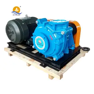
Explore a wide variety of hydraulic mud pumps on Alibaba.com and enjoy exquisite deals. The machines help maintain drilling mud circulation throughout the project. There are many models and brands available, each with outstanding value. These hydraulic mud pumps are efficient, durable, and completely waterproof. They are designed to lift water and mud with efficiency without using much energy or taking a lot of space.
The primary advantage of these hydraulic mud pumps is that they can raise water from greater depths. With the fast-changing technology, purchase machines that come with the best technology for optimum results. They should be well adapted to the overall configuration of the installation to perform various operations. Hence, quality products are needed for more efficiency and enjoyment of the machines" full life expectancy.
Alibaba.com offers a wide selection of products with innovative features. The products are designed for a wide range of flow rates that differ by brand. They provide cost-effective options catering to different consumer needs. When choosing the right hydraulic mud pumps for the drilling project, consider factors such as size, shape, and machine cost. More powerful tools are needed when dealing with large projects such as agriculture or irrigation.
Alibaba.com provides a wide range of hydraulic mud pumps to suit different tastes and budgets. The site has a large assortment of products from major suppliers on the market. The products are made of durable materials to avoid corrosion and premature wear during operations. The range of products and brands on the site assures quality and good value for money.

Explore a wide variety of hydraulic mud pump on Alibaba.com and enjoy exquisite deals. The machines help maintain drilling mud circulation throughout the project. There are many models and brands available, each with outstanding value. These hydraulic mud pump are efficient, durable, and completely waterproof. They are designed to lift water and mud with efficiency without using much energy or taking a lot of space.
The primary advantage of these hydraulic mud pump is that they can raise water from greater depths. With the fast-changing technology, purchase machines that come with the best technology for optimum results. They should be well adapted to the overall configuration of the installation to perform various operations. Hence, quality products are needed for more efficiency and enjoyment of the machines" full life expectancy.
Alibaba.com offers a wide selection of products with innovative features. The products are designed for a wide range of flow rates that differ by brand. They provide cost-effective options catering to different consumer needs. When choosing the right hydraulic mud pump for the drilling project, consider factors such as size, shape, and machine cost. More powerful tools are needed when dealing with large projects such as agriculture or irrigation.
Alibaba.com provides a wide range of hydraulic mud pump to suit different tastes and budgets. The site has a large assortment of products from major suppliers on the market. The products are made of durable materials to avoid corrosion and premature wear during operations. The range of products and brands on the site assures quality and good value for money.

This website is using a security service to protect itself from online attacks. The action you just performed triggered the security solution. There are several actions that could trigger this block including submitting a certain word or phrase, a SQL command or malformed data.

This website is using a security service to protect itself from online attacks. The action you just performed triggered the security solution. There are several actions that could trigger this block including submitting a certain word or phrase, a SQL command or malformed data.
When choosing a size and type of mud pump for your drilling project, there are several factors to consider. These would include not only cost and size of pump that best fits your drilling rig, but also the diameter, depth and hole conditions you are drilling through. I know that this sounds like a lot to consider, but if you are set up the right way before the job starts, you will thank me later.
Recommended practice is to maintain a minimum of 100 to 150 feet per minute of uphole velocity for drill cuttings. Larger diameter wells for irrigation, agriculture or municipalities may violate this rule, because it may not be economically feasible to pump this much mud for the job. Uphole velocity is determined by the flow rate of the mud system, diameter of the borehole and the diameter of the drill pipe. There are many tools, including handbooks, rule of thumb, slide rule calculators and now apps on your handheld device, to calculate velocity. It is always good to remember the time it takes to get the cuttings off the bottom of the well. If you are drilling at 200 feet, then a 100-foot-per-minute velocity means that it would take two minutes to get the cuttings out of the hole. This is always a good reminder of what you are drilling through and how long ago it was that you drilled it. Ground conditions and rock formations are ever changing as you go deeper. Wouldn’t it be nice if they all remained the same?
Centrifugal-style mud pumps are very popular in our industry due to their size and weight, as well as flow rate capacity for an affordable price. There are many models and brands out there, and most of them are very good value. How does a centrifugal mud pump work? The rotation of the impeller accelerates the fluid into the volute or diffuser chamber. The added energy from the acceleration increases the velocity and pressure of the fluid. These pumps are known to be very inefficient. This means that it takes more energy to increase the flow and pressure of the fluid when compared to a piston-style pump. However, you have a significant advantage in flow rates from a centrifugal pump versus a piston pump. If you are drilling deeper wells with heavier cuttings, you will be forced at some point to use a piston-style mud pump. They have much higher efficiencies in transferring the input energy into flow and pressure, therefore resulting in much higher pressure capabilities.
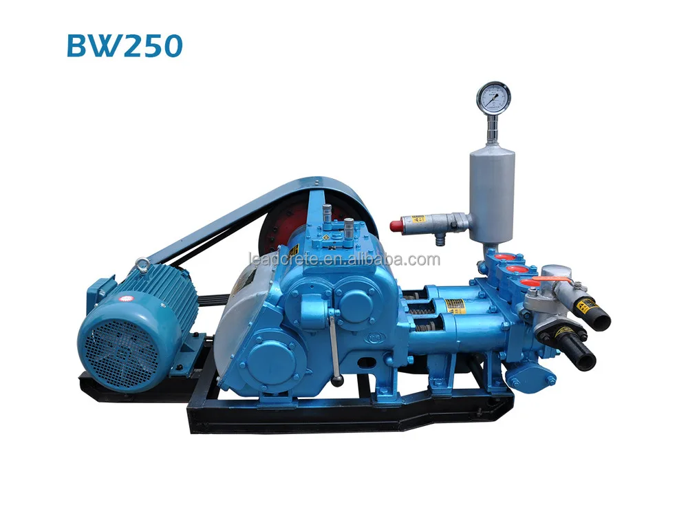
Piston-style mud pumps utilize a piston or plunger that travels back and forth in a chamber known as a cylinder. These pumps are also called “positive displacement” pumps because they literally push the fluid forward. This fluid builds up pressure and forces a spring-loaded valve to open and allow the fluid to escape into the discharge piping of the pump and then down the borehole. Since the expansion process is much smaller (almost insignificant) compared to a centrifugal pump, there is much lower energy loss. Plunger-style pumps can develop upwards of 15,000 psi for well treatments and hydraulic fracturing. Centrifugal pumps, in comparison, usually operate below 300 psi. If you are comparing most drilling pumps, centrifugal pumps operate from 60 to 125 psi and piston pumps operate around 150 to 300 psi. There are many exceptions and special applications for drilling, but these numbers should cover 80 percent of all equipment operating out there.
The restriction of putting a piston-style mud pump onto drilling rigs has always been the physical size and weight to provide adequate flow and pressure to your drilling fluid. Because of this, the industry needed a new solution to this age-old issue.
Enter Cory Miller of Centerline Manufacturing, who I recently recommended for recognition by the National Ground Water Association (NGWA) for significant contributions to the industry.
As the senior design engineer for Ingersoll-Rand’s Deephole Drilling Business Unit, I had the distinct pleasure of working with him and incorporating his Centerline Mud Pump into our drilling rig platforms.
In the late ’90s — and perhaps even earlier — Ingersoll-Rand had tried several times to develop a hydraulic-driven mud pump that would last an acceptable life- and duty-cycle for a well drilling contractor. With all of our resources and design wisdom, we were unable to solve this problem. Not only did Miller provide a solution, thus saving the size and weight of a typical gear-driven mud pump, he also provided a new offering — a mono-cylinder mud pump. This double-acting piston pump provided as much mud flow and pressure as a standard 5 X 6 duplex pump with incredible size and weight savings.
The true innovation was providing the well driller a solution for their mud pump requirements that was the right size and weight to integrate into both existing and new drilling rigs. Regardless of drill rig manufacturer and hydraulic system design, Centerline has provided a mud pump integration on hundreds of customer’s drilling rigs. Both mono-cylinder and duplex-cylinder pumps can fit nicely on the deck, across the frame or even be configured for under-deck mounting. This would not be possible with conventional mud pump designs.
Centerline stuck with their original design through all of the typical trials and tribulations that come with a new product integration. Over the course of the first several years, Miller found out that even the best of the highest quality hydraulic cylinders, valves and seals were not truly what they were represented to be. He then set off on an endeavor to bring everything in-house and began manufacturing all of his own components, including hydraulic valves. This gave him complete control over the quality of components that go into the finished product.
The second generation design for the Centerline Mud Pump is expected later this year, and I believe it will be a true game changer for this industry. It also will open up the application to many other industries that require a heavier-duty cycle for a piston pump application.
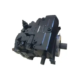
The Adtech Downhole Drilling Motor is a positive displacement hydraulic motor/pump powered by drilling rig mud or water. When the fluid is pumped through the tool the bit is turned at a speed proportional to the flow and remains relatively constant regardless of the load or developed horsepower. As weight is added to the motor and the bit start drilling the standpipe pressure will increase in direct proportion to the torque generated. This serves as a built-in indicator as to how the motor is performing, even if wall drag prevents an accurate response of the rig weight indicator.
Slow Speed: The motor operates at a speed more compatible with roller bits. This significantly lengthens bit life with increased on bottom time and fewer round trips.
Oil Filled - Sealed Bearing Section: Pressure compensated bearing section provides long seal life and more dependable bearing operation. Specialized Designs Adtech motors are specifically designed for the HDD market with advanced sealed bearing sections, oversized bearing packs and thick-walled stators
Design: All housings of the Adtech motor are tightened with controlled torque (breakout machines) and are locked to minimize accidental backoffs. Prior to shipment out to the field, each tool is thoroughly inspected and tested on our mud pump testing station to guarantee long, trouble-free operation.
Motor Section: The power section (rotor and stator) is the heart of the Adtech motor. The rotor is double plated with hard chrome to protect it from well bore fluids and abrasion. The stator is molded with an elastomer rubber that also resists the drilling environment. The rotor/stator configuration, stage length, and number of stages determine the speed and torque ratings of the motor. All motor parts are manufactured here at Adtech"s facility including the forming of the rotor and the injection of the rubber into the stator.
Bearing Section: The bearing section supports the weight on the bit and provides rigid lateral stability to the drive shaft. Four heavy duty roller bearings operating in synthetic oil permit high bit load and long bearing life. After assembly of the bearing section, the unit is completely evacuated to test for leaks and then filled with oil. This assures that there is no air in the system and allows the oil to flow freely through and around all of the components of the section. The system is filled under pressure to charge the oil reservoir and (after a topping) operation is bled back a calculated amount to allow for equalization of the oil pressure with the surrounding well bore hydrostatic pressure. This prepressure and pressure compensated oil system assures proper oil lubrication for the seals and bearing operation.
The Adtech Downhole Drilling Motor is an easy tool to operate provided it is operated within its design specifications. It should be noted that the specific use of any tool may vary from operator to operator and experience will show the most efficient and safe procedure to follow. It is recommended that a float be run above the tool to keep the bit or other parts of the tool from plugging. Though the tool is built to withstand normal wear and tear, care should be taken while running to depth since damage can occur from hitting bridges, casing shoes, junk or other obstructions in a hole. To run past these tight spots the motor should be operated at its normal speed. If a bent sub is used, the drillpipe (and motor) should be slowly rotated to prevent accidental side tracking of the main hole. As a guide, however the following steps are recommended for routine drilling operations:
Since the speed of the motor is proportional to the fluid volume it is important that the flow rate be accurately set and maintained throughout the drilling operation. When the tool has reached the correct depth and is off bottom, the flow should be set. This will establish the off bottom or no-load pressure the driller sees at the standpipe.
After proper cleaning of the hole, tool orientation, if applicable, should be performed before drilling ahead. As with all downhole drilling motors, the Adtech motor imparts a left-hand torque (tending to tighten the tool joints) into the string above/before the tool. This torque is equal and opposite to the torque generated at the bit while drilling. As weight is slowly added to the motor and the bit starts drilling, the pressure will increase in direct proportion to the torque generated. Assuming everything but the weight on the bit remains constant in any specific drilling situation, the rig pressure gage will be an indicator of the weight on the bit and especially useful piece of telemetry where wall drag prevents an accurate response of the rig weight indicator. If the rig pressure gage does not respond as indicated and the tool does not drill off as predicted, see the section titled Trouble-Shooting. As initial drilling commences a little difficulty may be encountered in getting the tool to drill smoothly. This is due to the bit seating in on the previously drilled formation and will disappear in a short time.
To obtain the best performance from the Adtech Downhole Drilling Motor, it is necessary to use the tool within the specifications and limitations for which it is designed. Care should be used in selecting the right size tool for the right job. Due to the high torque capability of the motor, there may be a tendency to use a tool that is really too small for the job resulting in unsatisfactory performance due to the flow and strength limitations. Tabled below are the general specifications of the motors that are now or soon will become available. These specifications will change from time to time as improvements are incorporated.
Sometimes due to rig or hole conditions it may be necessary to operate with flow rates other than that recommended in the table. Since the listed operating speed of the motor is directly proportional to the flow its change should also be considered. The output torque of the motor is, however, generally independent of the flow and therefore little change of the allowable weight on the bit should be realized. Changing the flow will, of course, change the bit hydraulic horsepower and this coupled with the change in bit speed will in many instances affect the drilling rate of penetration. The tool should never be operated more than 15% above the designed operating flow due to the high pressure drop and flow velocities through the tool. Also operating more than 30% below the recommended flow will result in a lower speed and therefore a decreased rate of penetration and performance. If it is desired to operate below the designed flow, it is recommended that the motor first be started with the designed flow and then adjusted back as required.
When drilling is first started, it may take 10-15 minutes for the bit to seat in the previously drilled formation before drilling will proceed smoothly. However, if the motor does not take pressure and drill off as predicted, the following outline may help in correcting the situation. It should be noted though, that most operators have acquired years of experience with drilling motors and have possibly seen every type of malfunction. In each case the operator may use his own particular trick to remedy the problem:
Is the motor sanded-up? An especially dirty hole of faulty float valve could have allowed solids to settle within the motor causing the drilling fluid to channel rather than turn the motor. Continuous pumping (15 minutes maximum) will sometimes correct such a condition. Also during this time slow rotation of the pipe (to the right) while gently tagging bottom will sometimes free the motor.
If none of the above (or other) corrective actions prove unsuccessful, it will be necessary to trip the tool from the hole. While tripping check for drill pipe and drill collar for washouts to be sure calculated flow was actually getting to the tool. Surface check the tool by pumping through at normal flow rates and watch for normal rotation. If the tool does not rotate pump through for 15 minutes to see if it clears itself. If the motor turns at about half its normal speed check the bypass valve again to be sure that it is actuating freely. Check for anything unusual, as for example, pieces of metal or rubber trapped in the bit, a bent bit sub, etc.
If the tool still does not perform satisfactorily file a report on the form provided in the lifting sub and return in the sub when wending the tool back for redressing. If you desire the results of the factory tool inspection contact your Adtech representative or indicate on the form enclosed in the lifting sub. Adtech will make every effort to determine exactly the cause of malfunction and provide you with a full report if desired.
The bearing section of the Adtech Downhole Drilling Motor has been completely filled with oil at the factory and should not normally require any additional service at location. However, for unusually long runs the oil level should be checked in the field to be sure the bearings are operating with the proper amount of lubrication. More information on checking the oil level may be obtained from your Adtech representative.
In operating the Adtech Downhole Drilling Motor, the most important items to watch to assure a successful run are the motor and system hydraulics. It cannot be overemphasized that reliable, high performance will be obtained by close attention to the proper hydraulic requirements. If desired, the Adtech motor can run with diamond bits with one important note. The pressure drop across a diamond bit is caused by friction as the drilling fluid flows between the bit surface and the formation. This pressure drop will vary as the bit is put on bottom and increase as the fluid must pass through the small area between the fluid-courses on the bit and hole itself. In diamond drilling, it should also be noted that the difference in standpipe pressure between drilling and rotating off bottom is due to the pressure increase across the bit and the normal pressure required to produce power by the motor. By subtracting the designed bit pressure drop, the actual motor pressure increase associated with its torque generation can be determined.
The Adtech motor, being a positive displacement motor, will run at a specific speed (RPM) for a specific volume (gal/min.) throughout. The required circulation rate as discussed under Specifications should be established prior to drilling and maintained throughout the drilling program for optimum tool performance. For duplex and triplex piston pumps, the flow rate depends on the length of the pump stroke, liner size, number of strokes per minute, and efficiency. For easy reference, the circulation rate for various sizes of pumps is shown in Appendixes F and G. For duplex pumps, these tables were prepared using 95% efficiency for under 40 strokes per minute and 90% efficiency for over 40 strokes per minute. The triplex pump information is shown at 100% efficiency.
The Adtech motor is designed to effectively handle most drilling fluids including lost circulation material. However, since the long term performance of the motor depends so heavily on the mud as its source of power more attention will be given to it here. Regular and complete testing of the mud is important not only to the prevention of damage to the motor but also to the success of drilling and maintaining the hole condition as well.
Particular attention should be given to the following items: Lost Circulation Material As a general rule anything the rig pump can handle can also be handled by the drilling motor. Care should be exercised however in adding these materials to the mud system so that the system is not slugged with large quantities at one time. These could become lodged within the motor or bit passageways. Also it is advisable to run the rig pumps with screens to avoid extra large debris from entering the system. Rags and tools accidentally dropped down the circulating system will severely plug and damage drilling motor.
Just like sand and abrasive solids will damage the rig surface equipment the drilling motor will likewise be adversely affected. If possible, desanders should always be used and kept working correctly. Maximum sand content should be no more than 2% by volume with a preferred content of less than 1%. It should be noted that the standard API measurement for sand considers particles only greater than 200 mesh in size. However, smaller particles, depending on their hardness and shape will remove approximately as much material as the courser sand. These finer particles will be found in the solids content of the mud and will have to be removed if present.
This invention relates generally to piston pumps for the water well drilling industry, and more particularly to a hydraulic cylinder powered double acting duplex piston pump.
Double acting duplex piston pumps are well known and have been used in the water well drilling industry for many years. Typically they employ a crankshaft and flywheel driven in various ways, a reciprocating engine or a hydraulic motor being examples. Typically, they are heavy units with a large component of cast iron. Today"s well drilling trucks carry lengths of drilling pipe, as well as derricks, motors, pumps of various kinds, and the “mud” pump. The current double acting duplex piston pumps with crankshaft and flywheel, being very heavy, contribute significantly to the weight and space requirements of the truck. They impact the ability of a truck to meet federal highway weight restrictions. Also, the mechanical crank throw design imparts a variable speed to the mud pump piston. In such designs, the piston is either accelerating or decelerating during a large part of its design stroke. So the piston operates at its full design capacity during only a portion of the stroke. Therefore, it is an object of the present invention to provide a duplex piston pump useful as a mud pump on a water well drilling machine, but without a motor, crankshaft, flywheel, gearing, and/or belts, for a significant weight reduction.
Described briefly, according one embodiment of the present invention, a mud pump is provided with two working cylinders for pumping mud, and two sets of double-acting hydraulic driving cylinders. One set of two driving cylinders has the piston of each connected to the piston of one double-acting mud pump cylinder. The other set of two driving cylinders has the piston of each connected to the piston of the other double-acting mud pump cylinder. The connection of a set of driving cylinder pistons to the mud pump piston is through a member which allows side-by-side, or over and under parallel arrangement of the driving cylinders and mud pump cylinders, so the overall length is minimal. An electro-hydraulic control system is provided to coordinate the action of the pump driving cylinders with the mud pumping cylinders for contributing to steady flow of mud from the mud pump.
FIG. 2 is a schematic elevational view of one of the two pump assemblies of the duplex piston pump according to one embodiment of the present invention.
FIG. 3 is a schematic diagram of a system according to the illustrated embodiment and showing both of the duplex mud pump cylinders, with one of two hydraulic driving cylinders for each of the mud pump cylinders, and including an organization of hydraulic flow divider, rod position sensing, proximity-type electrical switches and associated electrical relays for solenoid-operated hydraulic fluid directing spool valves associated with the hydraulic cylinders.
FIG. 6 is an example of a flow chart relating mud pump speed to mud pump output volume capacity and hydraulic driving oil volume requirement for a pump according to the illustrated embodiment of the present invention.
FIG. 7 is a diagram showing theoretical pump driving cylinder piston performance of the two sets of mud pump driving cylinders operating according to the illustrated embodiment of the present invention.
For the purposes of promoting an understanding of the principles of the invention, reference will now be made to the embodiment illustrated in the drawings and specific language will be used to describe the same. It will nevertheless be understood that no limitation of the scope of the invention is thereby intended, such alterations and further modifications in the illustrated device, and such further applications of the principles of the invention as illustrated therein being contemplated as would normally occur to one skilled in the art to which the invention relates.
FIG. 1 shows, schematically, a normal environment in which the mud is pumped by duplex piston pump 5 of the present invention from the chip separation tank 6 through the pump and the discharge the line 7 into the top of drill pipe 8 and down in the drill pipe and out into the well casing at the drill bit 10. The mud flows upward through the casing and back into the separation tank 6. The pump itself includes two mud pumping cylinders 1 and 2 fixed relative to a base 3 (FIGS. 5A and 5B) by mounting to four housings 4L, 4F, 4R and 4B which are fixed to the base.
As suggested above, according to the present invention, an all-hydraulic drive for the two mud-pumping pistons in cylinders 1 and 2 is achieved. For that purpose, and referring to FIG. 3, a variable volume hydraulic pump P is used. It can be set, for example, at a rate of 36 gallons per minute at 1,000 psi. A motor M can be used to drive such a pump, and such pumps and drives for them are known in the art and readily available. The pump output is fed to a flow divider D. This is not merely a device to split the flow. Instead, it has a piston inside which will shift in either direction to the extent necessary as it tries to be sure that the exact same volume flow rate is delivered at both output ports of the flow divider. An example of such a flow divider is Model MH2FA by Rexroth Worldwide Hydraulics.
Before proceeding further with this description, it is important to understand that each half of the duplex piston pump includes a double-acting mud pump cylinder and piston assembly. FIG. 2 shows one of the halves including mud pump cylinder 1. The other half, including a mud pump cylinder and associated hydraulic driving cylinders is identical. FIG. 5A shows, schematically, a rod end view of the duplex piston mud pump 5 including the mud pump cylinders 1 and 2 and associated driving cylinders of both halves.
The mud pump cylinders and their associated driving cylinders may be fixed relative to each other and mounted to the base 3 by any suitable means. The schematics of FIGS. 5A and 5B show, as an example, the four valve housings 4F, 4L,4B and 4R fixed to base 3. Except for right and left ports, each of these housings is the same as the others, and includes therein a chamber such as 41C having an opening 41A communicating with a port of a mud pump cylinder such as cylinder 1 or 2. Each chamber 41C also has two other openings. One of them is fitted with a one-way, spring loaded outlet valve such as 16 to enable mud to move from chamber 41C into the upper end of housing 4L and out through port 41D into the discharge plenum 7A. The other opening 41E of chamber 41C is fitted with a spring loaded inlet valve such as 14 communicating with the lower end of housing 4L and enabling mud entering suction inlet 6A of the mud suction manifold 6B to enter through port 41E in housing wall and into chamber 41C. The mud pump cylinders are attached to their respective valve housings in conventional manner with the ports of the cylinders communicating with the respective chambers of the housings.
Referring now to FIGS. 2 and 5A and 5B together, FIG. 2 shows schematically mud pump cylinder 1 and inlet and outlet valves 11 and 12, respectively, associated with the pump port at one end of cylinder 1, and inlet and outlet valves 14 and 16, respectively, associated with the pump port at the opposite end of cylinder 1, the rod-end of the cylinder. In practice since there would normally be only one port at each end of the cylinder, the valves would be in the housings 4L and 4F for cylinder 1. There is a packing gland 17 at the rod-end of the cylinder. In FIG. 5B the top of housing 4L is cut away to show discharge valve 16. Suction or inlet valve 14 below chamber 41C is shown larger in dashed lines to be able to see it in FIG. 5B, as it is the bottom of chamber 41C, FIG. 5A.
According to one feature of this invention, there are two hydraulic driving cylinder/piston assemblies 19 and 21 arranged in a way to drive the mud pump piston 1P in cylinder 1. As suggested above, cylinders 1, 19, and 21 are all connected relative to each other by some suitable means (brackets and/or clamps, for example) so that they are longitudinally immovable relative to one another. This is represented schematically for both sets of mud pump and driving cylinders at the valve housing 4L, 4R and associated inlet and outlet and base in FIGS. 5A and 5B, to which all of the six cylinders of both halves of the duplex pump are rigidly, but removably connected. Each of the two driving cylinder assemblies for piston 1P has a piston rod such as 19R and 21R bolted to a rod connector plate 22. Each rod may extend through the piston and exit the driving cylinder at the end opposite the plate-connected rod end, as indicated at 19S and 21S. The respective pistons 19P and 21P are affixed and sealed to the rod in a suitable way and may be of any suitable construction. Of course, the same effect may be achieved using separate colinear rods secured to opposite faces of the pistons. The piston rods 19R and 21R of the driving cylinders for mud pump cylinder 1, and rod 1R of the mud pump cylinder 1 itself, are bolted to the rod connector plate 22. Each of the rods 19R, 19S and 21R, 21S is supported at opposite ends of the respective cylinder by bearings and seals at 19B and 21B, respectively. Using double rod cylinders provides equal working area on the two sides of the piston, enabling equal oil flow and thrust capacity in both directions of piston travel. One or the other of the driving cylinder rods for mud pump cylinder 1 is associated with a set of proximity sensing switches A-1, B-1, C-1, and D-1 to operate a relay to shift a hydraulic solenoid valve spool to control hydraulic fluid to and from the set of two driving cylinders 19 and 21 to drive the mud pump 1. The same kind of arrangement is provided for mud pump cylinder 2. For each set, the driving cylinder which has the associated proximity switches, may be referred to hereinafter from time-to-time, as the control cylinder.
In this particular arrangement, only as an example of cylinder and rod size, the mud pump cylinder may be six inches in diameter with a twelve inch stroke, using the pistons of two driving cylinders of two inch diameter each to drive the one mud pump piston. A significant advantage can be achieved by making the rods of the driving cylinders larger in diameter (1.375 inches, for example) than that of the mud pump cylinder rod (1.25 inches, for example). It enables use of larger and longer wearing bearings in the driving cylinders, and enables the use of a relatively small piston rod and packing gland 17 in the mud pump cylinder, thus minimizing exposure to wear of the packing gland. The combination of the large diameter rods in the driving cylinders, fixed to a rigid rod connector plate 22 to which the mud pump cylinder rod is bolted, contributes to a very rigid structure. It avoids the necessity of a very long arrangement and long piston rod spans which would be necessary if the mud pump cylinder was driven by a single piston in a hydraulic cylinder on the same longitudinal axis. That would require a more complicated bearing arrangement to support the mud pump cylinder rod. In the present arrangement, the cylinder rod bearings are relatively close to the mud pump packing gland, helping extend the life of the gland by minimizing radial working and resulting loading of the mud pump rod on the packing gland. Also, with the present arrangement, the driving cylinder rods are in tension when the mud pump rod is in compression, which reduces the bending moment.
The proximity sensor switches A-1 through D-1 are responsive to movement of an actuator such as flange 19F on rod 19R, 19S. These switches may be normally-closed or normally-open switches as a matter of convenience in the construction of the circuitry. It should be understood, of course, that the other half of the duplex double acting pump assembly which includes cylinder 2, has driving cylinders such as 29 and 31 associated with it, and proximity switches associated with the piston rod of one (29, for example) of those driving cylinders, (shown in FIGS. 3 and 5A) in the same manner as for the assembly shown in FIG. 2. The position of the piston in cylinder 1 is preferably in a different location and/or it is moving in a different direction, from that of the piston in cylinder 2.
Referring now to FIG. 3, mud pump cylinder 1 and mud pump cylinder 2 are shown schematically, as is one cylinder of each set of two driving cylinders for each of the two mud pump cylinders 1 and 2, respectively. Since the mud pump cylinders are virtually identical and the two driving cylinders of the set for each of the mud pump cylinders are virtually identical, a description of one driving cylinder and associated controls will suffice for both.
The output from flow divider D enters the center input port of a two-position, solenoid-actuated, spring-return hydraulic valve V-1. This valve is electrically coupled to a relay switch R-1 which is bi-stable and electrically coupled to the proximity sensor switch A-1. An example of a suitable relay is No. 700-HJD32Z12 by Allen-Bradley. It is a DPDT latching relay. One switched position of this relay switch R-1 causes the solenoid to be energized to open the valve and supply pressurized oil from valve V-1 through line L-1 to the one end of cylinder 19 and likewise cylinder 21 of FIGS. 2 and 5 to drive the pistons in the direction of the arrow 23. This occurs in both driving cylinders 19 and 21, so rod 13R, being mechanically fixed to the two driving cylinder rods 19R and 21R by rod connector plate 22, is likewise driven in the direction of the arrow 23. When relay R-1 is reset by a signal from another proximity switch which can be recognized upon study of FIGS. 4A through 4D, it de-energizes the solenoid for valve V-1, enabling the spring therein to return the solenoid to position where the supply to the cylinder 19 is through line L-2, to reverse the direction of the piston in that cylinder and its companion driving cylinder, thus reversing the direction of the mud pump piston 1P. Whichever side of the piston is not pressurized at any time is enabled to dump through the valve V-1 to sump S-1. Essentially the same arrangement exists for control and drive of mud pump cylinder 2. In this instance, the proximity switches are designated A-2, B-2, C-2 and D-2. The relay switch is R-2 and the control valve is V-2 operated by a solenoid. It should be mentioned at this point, however, that while the pistons in the driving cylinders for one of the mud pump cylinders are located in the same relationship to each other as the mud pump cylinder with which they are associated, they are typically out of phase with respect to the mud pump piston and pistons of associated drive cylinders of the other mud pump cylinder. This is intentional in an effort to be sure that the flow out of the mud pump assembly 5 is as stable and constant as possible. That is the goal to which the organization of the proximity switches and associated relay switches are directed. Also with reference to FIGS. 2 and 3, it should be mentioned that the supply lines L-1 and L-2 to cylinder 19 are larger than the lines from cylinder 19 to cylinder 21. This is because the lines from valve V-1 go directly to only one of the two driving cylinders and from that point, are directed to the other driving cylinder. Thus, the supply lines L-1 and L-2 must be large enough to drive both driving cylinders 19 and 21 with essentially equal pressure and volume capacity. This is shown schematically in FIG. 2 with lines B-1 and B-2 from cylinder 19 to cylinder 21.
Referring now to FIGS. 4A through 4D, along with FIG. 3, FIG. 4A is a simplified portion of FIG. 3. It includes a driving cylinder 19 for mud pump cylinder 1, and driving cylinder 29 for mud pump cylinder 2. It also shows the proximity switches A-1 and B-1 associated with the piston rod portion 19S of cylinder 19. Similarly, proximity switches A-2 and B-2 associated with the piston rod 29S of driving cylinder 29, are shown. The position of the rod 19S relative to rod 29S is only for purposes of example, as it is not expected that the pistons of cylinders 1 and 2 will ever be positioned at the same longitudinal location relative to each other unless they are passing as one goes in one direction and the other goes in the other direction. But the purposes of the proximity switches A-1 and B-1 is to limit the travel of the piston in the two directions. Thus, either the switch A-1 or the switch B-1 can set or reset relay R-1 to cause the valve V-1 to shift and switch the high pressure from valve V-1 to either line L-1 to move the driving piston and thereby the mud pump piston 1P to the right, or apply the high pressure to line L-2 and drive the driving piston and thereby, the mud pump piston 1P to the left. Regardless of which direction the mud pump piston is moving, it will be drawing mud from the chip separation tank 6 and discharging it to the manifold connected to discharge line 7. The arrangement and operation is true regarding driving cylinder 29 and the proximity switches and relay R-2 and valve V-2 associated with that piston rod 29S.
To assure that the pistons of the two mud pump cylinders are never at either end limit of their strokes simultaneously, two additional proximity switches C-1 and D-1 (FIGS. 4B and 4D) are added. Each of these can be located about 2 inches, for example, from the proximity switches A-1 and B-1 and functions in the same way as described above with respect to switches A-1 and B-1.
The control system of FIG. 4D provides the combination of components to achieve two objectives. The first, and probably the more important, is to insure that the set of power cylinders 19 and 21 for mud pump cylinder No. 1 will cycle independently of the set of power cylinders 29 and 31 for mud pump cylinder 2, providing a 12 inch stroke for each of the mud pump cylinder rods independently of the other rod. A scheme for accomplishing this is shown generally in FIG. 4A where the sensor A-1 or the sensor B-1 can energize the latching relay R-1 at opposite ends of the piston rod stroke.
Another objective is to build a system which will insure that the piston 1P for mud pump cylinder 1 does not reach the end of its individual stroke at the same time as the piston 2P for mud pump cylinder 2. That could occur when both pistons are side-by-side and going in the same direction (FIG. 4B, for example) or when they are phased 180 degrees apart, so going in opposite directions and nearing the ends of their strokes (FIG. 4C, for example). These conditions are more complex and are addressed by the additional components shown in FIGS. 4B and 4C.
In addressing this problem, it should be recognized that the mud pump pistons could arrive at the ends of their strokes at the same time even if not necessarily together mid-stroke, but they would probably have been together at least a short distance before they reached the ends of their strokes. In FIGS. 4B and 4C and the above description, a two inch distance from the end of the stroke is mentioned and shown, but this distance could be one inch or some other suitable distance. If the two pistons are together a short distance from the end of their strokes, it is likely that they would reach the end of their strokes at essentially the same time.
Since reaching the end of the stroke simultaneously for both mud pump pistons is not desirable, the present invention reverses one of the two pistons prior to reaching the normal end of the stroke. When one piston reverses, its stroke has been limited at 10 inches. This will place the two mud pump pistons out of phase for an extended period. For this purpose, the additional proximity switches C-1 and D-1 for piston rod 19S, and C-2 and D-2 for piston rod 29S, are added, as mentioned above. For the right combination of signals, to correctly use the proximity switches C-1, C-2, D-1 and D-2, additional relays R-3, R-4, R-5 and R-6 can be used. An example is a DP/DT, a stable (non-latching) relay by Siemens, Potter & Brumfield Division.
The combination of the foregoing components for the control functions as described above and shown in FIGS. 4A, 4B and 4C, results in the control component organization of FIG. 4D which is a consolidation of the systems of FIGS. 4A, 4B and 4C, to achieve the above-mentioned goals of having the power cylinder set for mud pump cylinder 1, cycle independently of the power cylinder set for mud pump cylinder 2, and avoiding the simultaneous arrival at the end of their strokes of mud pump piston 1 and mud pump piston 2. At this point it should be understood that specific implementation of controls is not limited to the above-described organization of proximity switches, activators for them, types of valves or relays, whether electrically or pneumatically controlled, or the specific organization of an electrical, pneumatic, or optical control circuit, for example, portions of which may be solid state discrete devices, or integrated circuit organizations, as it will depend largely on the preference of and choices by a control circuit designer and well within the skill of the art of one who understands the organization and intentions and implementation described above, according to the present invention.
Initially, in the practice of the present invention according to the illustrated embodiment, it is intended that valving and control as shown in FIG. 4D and described above, or in such other scheme as may be preferred, be used so that when a constant flow of hydraulic oil is delivered into the system by the hydraulic pump P, relatively constant mud flow from the double acting duplex mud pump will be possible. With the present invention, the flow divider D (FIG. 1) is truly a flow divider, attempting to deliver the same volume at both outlet ports. To do so, it attempts to adapt to any difference in operation of one of the mud pump pistons relative to the other, by adjusting the pressure. For example, if the piston rod packing in one mud pump cylinder is tighter on the rod than on the other mud pump cylinder, the flow divider spool centering springs will tend to move the spool in a direction attempting to establish the same amount of flow to both of the hydraulic oil driving cylinders. Also, when one mud pump driving cylinder set piston reaches the end of its stroke, what would otherwise appear to be a sharp rise in pressure to be handled by the flow divider, can be tolerated by the flow divider itself so as to avoid damaging mechanical or hydraulic shock. This effect is somewhat mirrored in FIG. 7 which shows in the solid lines, the wave form of pressure available from the mud pump cylinder 1 for one stroke cycle, that being a full stroke from left to right, and a full return stroke from right to left in FIG. 3, for example. The dashed wave form represents the available pressure from mud pump cylinder No. 2. In this illustration, the discharge pressure in cylinder 1 begins a sharp rise from 0 at point A to a maximum available pressure at point M and then drops sharply beginning at point N to 0 at point R. Then it rises on the opposite side of the piston sharply at point R to the same maximum level and then drops again to 0 at point S. Meanwhile, if the pistons of the two mud pump cylinders happen to be operating at 90° phase relationship, the available pressure from the cylinder No. 2 follows the dashed line. Both of these pressure “curves” are essentially a square wave, in contrast to the somewhat sinusoidal output of a conventional, crankshaft-driven duplex piston pump. At point A, when the pistons in the driving cylinders for cylinder 1 get to the end of their stroke, the hydraulic pressure on the driving pistons rises sharply until the pistons begin moving in the opposite direction. This is because of the fact that, when the pistons of either driving cylinder set reach the end of their stroke, and the related solenoid valve is shifting to change the direction of the piston, there is no flow of oil through this valve. With a constant input flow of oil, it must be re-routed to prevent pressure build-up in the system and popping pressure relief valve, and also to prevent a volume drop in the discharge of the mud pump. The flow divider D has tolerance to enable this temporary re-routing to the driving cylinders 29 and 31. At the same time, with the additional pressure on these cylinders driving pump 2, a pressure spike may result in mud pump cylinder 2 such as shown in the dashed line at A and R and S in FIG. 7. The spike could be at other locations, depending upon the phase relationship of the cylinder set for mud pump cylinder 1 and the cylinder set for mud pump cylinder 2. Thus with a less than 100% accuracy-style flow divider D, the excess oil from one shifting solenoid valve is routed to the other (open) solenoid valve and driving cylinder set, which increases in speed and keeps the mud pump discharge constant. The oil itself becomes an accumulator and pressure relief system, operating at the exact same pressure over the full range of the operating system and produces the effect of constant velocity pistons in the mud pump.
Since these driving pistons are not driven by a crank shaft, they operate at essentially constant velocity. In other words, whereas a piston driven by a rotating crank shaft moves according to a harmonic sine wave pattern, a piston driven according to the present invention defines essentially a square wave pattern. In a conventional pump where the piston is driven by a rotating crank shaft, the inlet and outlet valves must be designed and sized to permit maximum flow, which typically occurs at the time of maximum travel of the piston, which occurs when the crank pin axis and rotational axis of the crank shaft are in a plane perpendicular to the axis of the piston. In contrast with construction according to the present invention, the inlet and outlet valves are sized to a maximum flow which is essentially constant regardless of where the piston is during its stroke, and which is only limited by the flow available from the flow divider. Therefore, as an example, where a conventional 5×6 mechanically driven pump using 5×6 valves, would handle about 150 gallons per minute, a pump according to the present invention with a 5″ diameter bore and 6″ stroke could be expected to produce on the order of 300 gallons per minute although using the same size “5×6” valves. Accordingly, the present invention provides the possibility of approximately twice the volume capacity with significantly less space and weight by virtue of the essentially constant velocity pistons, and significantly less overall length.
Referring again to FIG. 3, with the pump P delivering 36 gallons per minute, for example, the flow divider delivers approximately 18 gallons per minute through each output port, and which is delivered to the hydraulic driving cylinders. It should be understood that pumps having other capabilities in terms of volume and pressure can be employed. The 36 gallon per minute number is selected to match one combination of pump valves and suction hose size. Other combinations can be made for other sizes of suction hose, valves, and operating speeds, and are within the skill of the art. If there is no imbalance in the loads on the pistons of these sets of hydraulic cylinders, each of them can move at the rate determined by 18 gallons per minute flow into the cylinder at 1,000 psi (ignoring friction losses in the lines).
Because of the relative differences in sizes of the driving cylinders and the mud pump cylinders, and again, ignoring friction losses, the mud pump cylinders will be able to deliver 100 gallons per minute at 200 psi.
As suggested above, in the practice of the present invention, the oil of the piston pump system is used to absorb the undesirable pressure peaks of the primary hydraulic system. Resistance of the mud pump hydraulic system can offset the inertia of the traveling pistons and the piston rods when they reach the end of their stroke. The problem of moving excess oil during the time the valve spools are shifting, is addressed to avoid pressure peaks and consequent opening of the relief valves on each stroke. This problem of moving excess oil is solved by using an open system between the two sets of driving pistons. When the control valves close to change the direction of one set of pistons, the oil is free to flow to the other set of pistons which may be in the middle of their stroke operating at the same pressure. The volume of liquid lost in one mud pump cylinder is made up by the increase in the other, insuring that the mud pump discharge remains constant.
The pressurized side of a hydraulic cylinder is free to accelerate, based on the flow of oil being supplied. But the suction side of a mud pump piston has additional forces. Such piston velocity can only accelerate at a rate based on the flow of liquid moving through the suction valve. When a force is applied to increase the piston to a speed exceeding the incoming flow, increased vacuum forces or cavitation develops and the mud pump cylinder walls tend to deteriorate. Using an open-type system according to the present invention, some portion of supplied driving oil is free to move from the driving cylinder set for the starving cylinder through the flow divider to the driving cylinder set, reducing the acceleration rate and damage to the starving mud pump cylinder walls. Thus in the present invention, the primary hydraulic system can constructively interact with pressures of the secondary, mud management system.
In the water well drilling field, the application of a mud pump requires it to operate from zero to maximum pressure and zero to maximum flow as the drilling proceeds. This eliminates the opportunity to use standard accumulators and limit switches, as such devices must always be preset or designed for a given pressure. By using the open-to-atmosphere concept in the present invention, one of the two hydraulic piston sets is always working against the pressure developed by the resistance of the liquid (mud) being pumped. This liquid thus serves as an accumulator which is always working at the exact pressure required. Since the pressure is a function of the resistance of the fluid and the atmosphere, no relief valve is required.
While, the hydraulic driving cylinders are shown on top and bottom of a mud pump cylinder, other embodiments of the invention might have them beside or otherwise related to the mud pump cylinder as long as the piston rods of the hydraulic cylinders are somehow connected to the piston rod of the mud pump cylinder, so as to drive the mud pump piston. Also, some inventive aspects can be implemented with only a single hydraulic power cylinder for each mud pump cylinder, but using the accommodating flow divider and valve control system disclosed herein. While it is possible to make the cylinders the movable components, and other mixes and mechanical arrangements of rods and cylinders are possible, it is believed that making the rods the movable components simplifies the organization. In summary, the introduction of hydraulic power cylinders into a mud pump according to the present invention, eliminates the use of the complete power end (crankshaft, flywheel, etc.) of a conventional mechanically powered mud pump. Instead the cylinder power source provides a relatively constant velocity piston to move fluid at the piston"s rated flow essentially the full length of its design stroke. This permits a pump design with much smaller operating valves than would otherwise be required for the capacity required, contributing to a much smaller unit in size and weight.
While the invention has been illustrated and described in detail in the drawings and foregoing description, the same is to be considered as illustrative and not restrictive in character, it being understood that only the preferred embodiment has been shown and described and that all changes and modifications that come within the spirit of the invention are desired to be protected.

" RMATION TESTER G e o r g e H R a m s e y N v E N T OR Unit HYDRAULIC MOTOR OPERATED FORMATION TESTER Application January 29, 1954, Serial No. 407,119
3 Claims. (Cl. 166-100) This invention concerns a novel form of formation tester for use in testing the fluids which may be produced at a given point along a Well bore. The apparatus of this invention is of application in the exploration for oil and is. uniquely designed to provide simple and efficient means for sampling fluids produced in a bore hole at a given horizon or stratum ofthe earth.
In drilling a bore hole in the attempt to encounter oil deposits in the earth, it is conventional practice to employ a variety of tests to determine whether or not oil may be produced from the bore hole, todetermine the nature of the oil, it any, and to determine from which stratum or strata production should be attempted. The type of apparatus used to provide this type of information is generally called formation testing apparatus. This term aptly identifies the principal objective of the apparatus: .to test the fluids existing at a particular stratum of the earth. For this purposea wide variety of formation testers are known. A particularly attractive development of rather recent date has been the development of inflatable packer type formation testers. Testers of this type have an elastic packer whichmay be inflated by fluid. pressures. so as to completely seal oflf a particular portion of a bore hole. In one of its most desirable embodiments, a portion of the inflatable packer is provided with a permeable membrane, or alternative means, through which fluids maypass from strata ad- .jacent the sealed off section of the borehole into channels and chambers provided in the apparatus to receive the sampled fluids. This type of packer provides a convenient and effective manner of sealing off the drilling mud inthe bore hole so that. a sample of Well fluids can be obtained from any desired stratum of the bore hole.
One of the problems involved in obtaining fluid samples from a formation tester of this character is provision of a. suitable means for extractingfluid from the producing stratum. For example, it isoften unsatisfactory to rely upon use of a vacuum pump at the surfaceof the earth to produce fluid from a stratum. The limitation inherent in use of a vacuum pump is that an effective head of only about thirty feet of water may be applied on the producing stratum by this means. It
has been suggested to use a sample chamber which will be essentially evacuated when placed in fluid communication with the stratum to be sampled. In this case evacuation of a sample of fluid from the formation will be effectively. obtained; but itis apparent that the fluid capacity of the sample chamberis seriously limited. Consequently, it is one of the objects of this invention toprovide formation testing apparatus in which it is possible to obtain fluid flow from the formation to be tested into a substantially empty drill .pipe. This technique provides an ample pressure differential which is applied at the producing stratum so as to ensure production and recovery of any fluid which maybe present. Again, there is suflicient volume within the drill string (extending as it does to the surface of the earth) so that any ordinarily required volume of .fluid. sample may be withdrawn.
2,8412 10 Patented July. 8, 1958 Another problem connected with the use of inflatable packer type formation testers is provision of a suitable means. for inflating these packers. This problem becomes particularly diflicult to solve when provision is made, as indicated, for use of an empty drill. string into which the produced fluid is to flow. In this case it is apparent that drilling mud cannot be circulated downwardly through the drill string to inflate the packer and that other means are required. It is one of the features of this invention, therefore, to employ a hydraulic motor driven by the hydrostatic. pressure .of drilling mud .in the annulus of the bore hole about the drill string. This hydraulic motor may be directly coupled to a mudv pump which can be used toforce drilling .mud from the annulus of the bore hole"to inflate the packer. A particular advantage of this arrangement is the simple and effective operation made possible by effectivelyutilizing the pressure differential between drilling mud in the annulus .of the bore hole and the empty drill string.
The formation tester of this invention, having the characteristics generally indicated, may conveniently be designed to permit positive sequential operatingsteps. Thus, in a first step, inflation of the packer of the formation testeris achieved"by operation-of the hydraulic motor-mud pump combination. In a second step of the procedure the hydraulic motor and mud pump can be stopped and fluid can be produced through the inflated packer into the drill string. Finally, in a third step of the process the packer"can be deflated so that theentire apparatus can be removed from thebore hole, thereby bringing to the surface; the produced "fluid contained "within the drill string. It is one of the features of this invention to provide a sequential step-type valve operation to carry out these essential steps in formation testing.-
In" orderto fully illustrate the principles ofthis invention, reference will bemade to the accompanying drawings, in which the preferred form ofthe invention is schematically illustrated. In these drawings:
Referring to the drawings, the formation tester may be connected to a drill string 2 inorder to suspend the tester at any desired level in a bore hole. The uppermost portion of the tester constitutes a valve 3 operating within a valve body element 4 in which fluid" channels leading to the valve are positioned. As illustrated, the valve body 4 may be connected to the drill string 2 inthreaded relation. The valve 3" may constitute a plug valve held in the the, valve body by means of the cover plate 5. In order to permit sequential positioning of the valve, a torsion spring 6 is positioned about the valve stem so that in an initial step of the operation the valve can effectively be Wound up against the force of the spring 6. A ratchet 7 which may be suitably fixed to a support 8 carried by valve body 4 can be used to contact teeth out on the upper portion of the valve. As will bedescribed, the teeth are so.formed that each time the ratchet 7 is momentarily released the valve will turn one quarter of a revolution.
Any suitable means may be used to operate the ratchet 7 in order to turn the valve as desired. For example, a wire line 60 may be connected to the ratchet 7 so that the valve can be turned each quarter turn when desired. Again, for example, the ratchet may be controlled by a solenoid 61 supported by arm 62 from support 8 as shown in Figure 7 so as to control the different sequential valve positions. The solenoid may be operated remotely from the surface of the earth through suitable leads 63.
Suspended below the valve body 4 is a cylinder 9 within which is supported a centrifugal pump 10 and a hydraulic motor 11 which are diagrammatically illustrated by the rectangles in the drawing. Drilling mud maintained in the annulus of the bore hole has direct fluid communication with the inlet of the hydraulic motor through the port 12. The outlet of the hydraulic motor is connected to a conduit 13 which extends upwardly so as to connect with fluid channel 14 in the valve body 4. The hydraulic motor 11 may be directly coupled to the centrifugal pump 10 through a shaft 15. The inlet of pump 10 is normally in fluid connection with drilling mud in the annulus of the bore hole through port 17. As will be described, a. valve 18 may be used to close the port 17 when it is desired to discontinue operation of the centrifugal pump. The outlet of the centrifugal pump is connected to a conduit 19 which leads to a second fluid channel 20 in the valve body 4.
The cylinder 9 carrying the centrifugal pump and fluid motor may be fixed to the valve body 4 in any desired manner. For example, as shown, the cylinder 9 may be forc


 8613371530291