
industrial replace mud pump motor free sample

The 2,200-hp mud pump for offshore applications is a single-acting reciprocating triplex mud pump designed for high fluid flow rates, even at low operating speeds, and with a long stroke design. These features reduce the number of load reversals in critical components and increase the life of fluid end parts.
The pump’s critical components are strategically placed to make maintenance and inspection far easier and safer. The two-piece, quick-release piston rod lets you remove the piston without disturbing the liner, minimizing downtime when you’re replacing fluid parts.
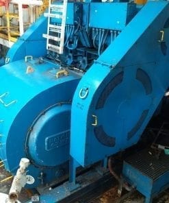
Cameron AC electric motors improve the performance of your mud pumps, drawworks, and rotary tables. Custom configuration is available, and ATEX, ABS, and DNV certification can be provided for new motors. Our flexible design offers you a choice between a tapered shaft or BullShaft to meet specific application requirements.
Cameron AC traction motors are designed and manufactured to handle deep drilling applications. Available in 400-hp, 550/600-hp, 1,150-hp, and 1,500/1,600-hp models, these inverter motors are designed specifically for 460-V to 690-V duty and deliver maximum efficiency. To meet varying installation requirements, our AC motors are available in vertical or horizontal designs.
Unlike conventional traction motors, Cameron AC motors have a unique design that meets the requirements of oil and gas applications. A key characteristic of the motor is the ability to provide a high level of torque at speeds ranging from 0 to 800 rpm (select motors can achieve a maximum speed up to 3,000 rpm). The torque generated at a wide range of speeds can enhance the performance of a broad array of drilling equipment driven by these motors.

The Liberty Process LL8 Progressive Cavity Pump is ideal for abrasive pumping applications such as drilling fluids with sand and grit common in fracking operations. As a Mud Pump, the LL8 Series is a popular model on many mobile pumping rigs in use today. Replacement mud pump parts are available as well from our stock and work on other popular manufacturers models.
LL8 parts are direct drop in aftermarket replacements that work with the *Moyno® L8 series, the *Tarby® TL8 series and *Continental® CL8 Series*. The Liberty unit is a low-cost, maintenance free, dependable drop-in replacement progressive cavity unit.
The Liberty LL8 is a standard flanged pump design manufactured with cast iron or 316 stainless steel pump casings designed in 1, 2, and 3 stages for 75, 150 and 225 psi discharge pressures and a flow rate of 18 up to 100 GPM.
The LL8 is a modular design with simple hardened pinned joint drive assembly. LL8 Rotors are typically hardened tool steel or 316 stainless steel with a hard chrome plating for long life in abrasive pumping applications.
All other wetted parts are either carbon steel or 316 stainless steel. Stators are available in many elastomer materials such as Buna Nitrile, Natural Rubber, EPDM and Viton. The standard seal design is a set of gland packing with a lantern ring set and flush connections. Mechanical seal options for this progressive cavity pump are readily available.
The LL8 represents one of the most popular progressive cavity pumps available for the transport of drilling mud with easily replaceable in-stock parts.

For 50 years, Giant Pumps has offered the most dependable positive displacement high-pressure triplex pumps available. Designed and built to the highest quality standards, customers count on Giant Pumps products to keep their equipment running. Every design detail of Giant Pumps products is optimized for long-life and reliable performance, making Giant Pumps the most trusted name in high-pressure pumps and systems.

Directional mud motors are the most proven and common method utilized by HDD contractors to complete installations in hard rock formations. Although mud motors are one of the more expensive and sophisticated pieces of equipment used in the industry, drilling contractors can incorporate certain procedures into their drilling program to minimize costs in utilizing motors and maximize motor performance while lowering their cost per foot.
As with other types of mechanical equipment, mud motors should be operated sensibly to provide a cost-effective balance of longevity, performance and dependability. Using a mud motor to ram and cram with high weight loading at high RPM and abrupt stalling and starting in abrasive rubbilized formations is analogous to operating an automobile by popping the clutch, running at redline, driving at high speeds over bumpy roads in a sand storm and sliding in curves. Here are some guidelines to get the most out of a motor.
During drilling, the motor is slid to steer or rotated to drill straight ahead. After being utilized in the sliding mode, the motor should be backed-off from the rock face a few feet prior to beginning the rotational mode. The driller should closely monitor the torque gage while initiating rotation to ensure the drill string is rotating freely. Rotation of the drill string should be limited to 20 RPM to 30 RPM in curved sections of the bore and not exceed 40 RPM in the straight sections. Rotation speed should not exceed 10 RPM to 20 RPM in severe angled sections of a bore.
Lower cost per footDuring drilling in hard abrasive formations, it is a good practice to ream build sections of the bore by pulling the motor and bit off bottom the entire joint up and back down while rotating the drill string 20 RPM to 30 RPM while pumping. This aids in cuttings removal, reaming the hole smooths the hole and reduces sticking risks. However, in softer sandstones, clays and shales this practice is not recommended due to erosion tendencies of these formations.
Weight on bit for optimum drilling rates is monitored by differential pressure (the difference between “on bottom” drilling pressure and “off bottom” circulating pressure). Normal operating differential pressure on larger motors (4 3/4 in./119 mm, 6 3/4 in./169 mm, and 8 in./200 mm) should not exceed 400 to 450 psi (28 to 31 bars) and 150 to 250 psi (10 to 17 bars) on smaller motors (2 7/8 in./72 mm, 3 3/8 in./85 mm, and 3 3/4 in./94 mm). If reasonable penetration rates can be achieved at lesser differential pressures then the weight on the bit should be maintained at these differential pressure levels. While using a motor, the best indicator of drilling weight on bit is differential pressure by monitoring the rigs mud pressure gage not the thrust hydraulic pressure gage. The “push” control can be constantly adjusted to maintain a steady pressure differential reading as rock formation is steadily eaten away by the drill bit. Hard rock drills slowly. Be patient.
Drill with clean mud. A good mud cleaning system not only increases rate of penetration and saves mud costs, but also reduces fluid cutting wear on mud motor internal parts and rig components as well. An analogy is an oil filter to remove grit in an automobile engine. A good cleaning system will remove solids down to 10 to 15 microns. A sand content test will show less than 1/8 (.125) of 1 percent sand.
Use a well-maintained mud pump of adequate output volume to match mud motor capacity. The mud motor can only convert available hydraulic power from the mud pump into rotation. The mud pump must provide enough gpm (Lpm) and pressure to the motor to get into its “power band” and then must be able to efficiently maintain the gpm (Lpm) level during loading without failing, bypassing, or sucking air. Usually it is most efficient to select a pump large enough to run at 50 to 70 percent of maximum output to avoid constant problems of overworking the pump.
Plan the bore and drill the bore to minimize sharp turning radii. The lower the bent housing angle on a motor, the lower the stress loading. If possible, do not exceed 2 degrees on a mud motors bent housing. Usually a 1 3/4 or 2 degree motor will provide more than adequate steerability control when utilized with the correct drill bit size and by practicing a “project ahead” program technique during drilling. Remember the closer the bit size ratio is to the motor OD size, the shorter the turning radius achieved from a given bent housing degree.
After using the motor, flush out the mud with a few gallons (liters) of fresh water. Store the motor in a safe place away from heavy mobile equipment. Consider having the motor serviced or swapped out if the next project start date allows time.
Frank McKenneyis vice president of INROCK Drilling Systems in Houston, Texas. The Drillmaster Reports are reviewed by a team of drilling professionals: Jerry Watson, INROCK Equipment Systems; Frank Canon, Baroid Industrial Drilling Products; and Mark Van Houwelingen, Vermeer Mfg. Co.

There are several questions that need to be addressed before we can move forward on this topic: How hard is the rock? Do we know what type of rock it is? What rig are you considering to use? How much mud pump volume (gpm) does your pump produce? How long is the bore? These are the opening questions that if answers are known, typically produce additional questions. If the rock has been tested to be 15,000 psi, I can move to the next question, but often all that is available is blow counts from a core sample run in the area. If that’s the case, I need to make some educated assumptions and move on. Looking at the type of rock gives me an indication of the potential wear on the motor — for example, shale is far more forgiving than sandstone. My customer now tells me he plans on using an 80,000-lb drill with a 250-gpm mud pump and the bore is 800 ft long. I now have enough information to make a recommendation for a mud motor for this project. Rock hardness is 15,000 psi in strength. The formation has been determined to be shale and limestone. We have an 80,000-lb drill with 250-gpm pump. Based on this information I can recommend a 4-3/4-in. mud motor.
This mud motor, as all manufactured motors do, has a specific flow range it operates in. For this size, it is 150 to 250 gpm. We try to optimize the flow rate to the motor to utilize its optimum torque output and rotation at the bit box. This should produce the best penetration rates and steerability in the rock — two things we always want to maximize (within the limits of hole cleaning ability). Other considerations are drill pipe outer diameter (OD). We hope to have the pipe similar in OD as the motor, which should mean similar mechanical limitations.
Now we can look at a bit size. As with the recommended flow range, there is a recommended bit size (OD) range. For a 4-3/4-in. mud motor, it is 6 to 7-7/8 in. Most of the time we like to see a bit in the 6-½- to 6-¾-in. size used. This will give the motor enough annulus area to properly reside in and also allow it to have the ability to properly steer. Oversized bits, for example an 8-½-in. bit on a 4-¾-in. mud motor, will not allow the motor to steer. The motor can’t contact the inner diameter of the bore hole, which eliminates the fulcrum effect of the bend in the mud motor.
If run within the operations manual specifications, the mud motor should perform within the published parameters up to 100 to 125 hours of drilling. At that time, it is recommended to be returned to the supplier for service and inspection. Typically at that time, we see the bearings out of tolerance and needing replaced. Obviously this is what we like to see but in our industry we face situations daily that can affect operations on the jobsite. We see many motors returned with 150-plus hours on them and usually these additional hours show on the repair bill. The internal workings of the transmission section are usually affected by the added hours, which will increase repair cost.
The most expensive replacement on the mud motor is the power section. This is comprised of the stator and rotor. The rotor is typically chrome-plated steel and has one less lobe than the stator, which its inner diameter is made of a highly engineered rubber compound. The drilling mud is pumped through the rotor-stator assembly, creating torque and rotation at the drill bit. This means the drilling mud needs to be clean of solids and sand. If it is not clean, it will prematurely wear the stator and the rotor, increasing the fit between the two, which dramatically reduces the pressure and power this section is designed to produce.
We once had a customer who bought a 6-¾-in. mud motor and after a month, I called to check to see if it needed service. I was told it was doing great and was in the hole on its third bore. I reminded the customer that service of the motor was critical to the overall life of the tool, but apparently it fell on deaf hears. Six months later, the customer called and said he was sending it in for service. I asked if he knew how many hours they had on it — I was told in excess of 750! Needless to say, the tool was retired and the rotor was made into a front bumper for one of their work trucks.
Service the motor every 100 to 125 hours of use and the overall life of the motor will be extended. Minimize motor stalls — this is when the motor stops turning internally while the mud pump is still pumping mud through it. After a motor is used on a job and doesn’t require service, we recommend that fresh water be pumped through it to flush out the drilling mud which will dry out and can cause damage when the motor is reused.
As long as a rig has the required gpm and pressure rating — I can answer a qualified yes. Let’s assume a contractor has a rig with a pump rated at 150 gpm by its manufacturer. This rating is based on pumping water with a new pump. So realistically, we have a pump that will probably pump mud at 100 to 120 gpm. This is enough flow to power a 3-½-in. mud motor in its mid flow range requirements. At that flow rate, we can check the motor’s performance curve and find we have around 550 ft-lbs of torque at 150 rpm. This will work well enough in rock up to 15,000 psi. But if the project is in rock that is 25,000 psi, it will dramatically reduce the penetration rate, lowering the ROP to a point that it becomes economically not feasible. In this case, the contractor would need a larger rig with a bigger mud pump to power a larger mud motor to overcome the compressive strength of the rock.
Another issue to consider when using a mud motor is the contractor’s ability to recycle and clean his drilling mud. If you are pumping 100 gpm, you will drain a 1,000 gal mud mixing system in 10 minutes, an obvious reason to recycle drilling mud.
Probably the most common mistake is what is done when a motor stalls out. A stall-out occurs when the bit stops turning while pumping. We have three mud pump pressure readings we monitor while using a mud motor. The first is the off bottom pump pressure reading; the second is the on bottom pump pressure reading; the third is the stall pressure reading.
Let’s say our contractor has an off bottom pressure reading of 500 psi and an on bottom reading of 750 psi. While drilling, he applies too much weight on the bit, causing it to stop turning. The pressure now reads 825 psi. At this point most drillers pull the motor off bottom and resume drilling. This method will send reactive torque up the drill string and could cause the motor or drill pipe to unscrew. The correct action to take when a motor stalls is to turn the pump off, and then pull the motor off bottom. Then, restart the pump and advance to bottom.
Another area of concern is the fact that you are doing your locating behind the mud motor. You have your drill bit, mud motor and crossover sub, then your steering system. It doesn’t matter if you are using a wireline steering tool or a walkover system — if the rig is using a 4-¾-in. mud motor, your steering system is 20 ft behind the drill bit. This usually causes the driller to overreact and drill an S-curved pilot hole. He sees he is heading right of centerline so he steers left, then he sees he is heading left so he steers right so on and so on. This situation will correct itself as the operator becomes used to drilling with a mud motor.

Pumps tend to be one of the biggest energy consumers in industrial operations. Pump motors, specifically, require a lot of energy. For instance, a 2500 HP triplex pump used for frac jobs can consume almost 2000 kW of power, meaning a full day of fracking can cost several thousand dollars in energy costs alone!
So, naturally, operators should want to maximize energy efficiency to get the most for their money. Even a 1% improvement in efficiency can decrease annual pumping costs by tens of thousands of dollars. The payoff is worth the effort. And if you want to remotely control your pumps, you want to keep efficiency in mind.
In this post, we’ll point you in the right direction and discuss all things related to pump efficiency. We’ll conclude with several tips for how you can maintain pumping efficiency and keep your energy costs down as much as possible.
In simple terms, pump efficiency refers to the ratio of power out to power in. It’s the mechanical power input at the pump shaft, measured in horsepower (HP), compared to the hydraulic power of the liquid output, also measured in HP. For instance, if a pump requires 1000 HP to operate and produces 800 HP of hydraulic power, it would have an efficiency of 80%.
Remember: pumps have to be driven by something, i.e., an electric or diesel motor. True pump system efficiency needs to factor in the efficiency of both the motor AND the pump.
Consequently, we need to think about how electrical power (when using electric motors) or heat power (when using combustion engines) converts into liquid power to really understand pump efficiency.
Good pump efficiency depends, of course, on pump type and size. High-quality pumps that are well-maintained can achieve efficiencies of 90% or higher, while smaller pumps tend to be less efficient. In general, if you take good care of your pumps, you should be able to achieve 70-90% pump efficiency.
Motor efficiency is also an important factor here. Motor efficiency depends on the fuel type, whether electricity or hydrocarbon, which in turn depends on availability and cost.
AC motors can achieve 90%+ efficiency when converting electrical to mechanical energy. Combustion engines are much less efficient, with typical efficiency ratings coming in at ~20% for gasoline and ~40% for diesel. Your choice of engine or motor type will depend on the availability and cost of fuel or electricity in your area.
Electric motors are more efficient than combustion engines, but site location and the cost of fuel can make the choice of combustion engines more practical.
Now that we have a better understanding of the pump efficiency metric, let’s talk about how to calculate it. The mechanical power of the pump, or the input power, is a property of the pump itself and will be documented during the pump setup. The output power, or hydraulic power, is calculated as the liquid flow rate multiplied by the "total head" of the system.
IMPORTANT: to calculate true head, you also need to factor in the work the pump does to move fluid from the source. For example, if the source water is below the pump, you need to account for the extra work the pump puts in to draw source water upwards.
*Note - this calculation assumes the pump inlet is not pressurized and that friction losses are minimal. If the pump experiences a non-zero suction pressure, or if there is significant friction caused by the distance or material of the pipe, these should be factored in as well.
You"ll notice that the elevation head is minimal compared to the discharge pressure, and has minimal effect on the efficiency of the pump. As the elevation change increases or the discharge pressure decreases, however, elevation change will have a greater impact on total head.
Obviously, that’s a fair amount of math to get at the pump efficiency, considering all of the units conversions that need to be done. To avoid doing these calculations manually, feel free to use our simple pump efficiency calculator.
Our calculations use static variables (pump-rated horsepower and water source elevation) and dynamic variables (discharge flow and pressure). To determine pump efficiency, we need to measure the static variables only once, unless they change.
If you want to measure the true efficiency of your pump, taking energy consumption into account, you could add an electrical meter. Your meter should consist of a current transducer and voltage monitor (if using DC) for electrical motors or a fuel gauge for combustion. This would give you a true understanding of how pump efficiency affects energy consumption, and ultimately your bank account.
Up until this point, we’ve covered the ins and outs of how to determine pump efficiency. We’re now ready for the exciting stuff - how to improve pump efficiency!
One of the easiest ways to improve pump efficiency is to actually monitor pumps for signs of efficiency loss! If you monitor flow rate and discharge (output power) along with motor current or fuel consumption, you’ll notice efficiency losses as soon as they occur. Simply having pump efficiency information on hand empowers you to take action.
Another way to increase efficiency is to keep pumps well-maintained. Efficiency losses mostly come from mechanical defects in pumps, e.g., friction, leakages, and component failures. You can mitigate these issues through regular maintenance that keeps parts in working order and reveals impending failures. Of course, if you are continuously monitoring your pumps for efficiency drops, you’ll know exactly when maintenance is due.
You can also improve pump efficiency by keeping pumps lubricated at all times. Lubrication is the enemy of friction, which is the enemy of efficiency (“the enemy of my enemy is my friend…”).
A fourth way to enhance pump efficiency is to ensure your pumps and piping are sized properly for your infrastructure. Although we’re bringing this up last, it’s really the first step in any pumping operation. If your pumps and piping don’t match, no amount of lubricant or maintenance will help.
Pipes have physical limits to how much fluid they can move at a particular pressure. If pipes aren’t sized properly, you’ll lose efficiency because your motor will have to work harder. It’s like air conditioning - if your ductwork isn’t sized appropriately for your home, you’ll end up paying more on your energy bill.
In this post, we’ve given you the full rundown when it comes to calculating and improving pump efficiency. You can now calculate, measure, and improve pump efficiency, potentially saving your business thousands of dollars annually on energy costs.
For those just getting started with pump optimization, we offer purpose-built, prepackaged solutions that will have you monitoring pump efficiency in minutes, even in hazardous environments.

Mud Pumps come in both electric and gas / diesel engine drive along with air motors. Most of these pumps for mud, trash and sludge or other high solids content liquid dewatering, honey wagon and pumper trucks. Slurry and mud pumps are often diaphragm type pumps but also include centrifugal trash and submersible non-clog styles.
WARNING: Do not use in explosive atmosphere or for pumping volatile flammable liquids. Do not throttle or restrict the discharge. Recommend short lengths of discharge hose since a diaphragm mud pump is a positive displacement type and they are not built with relief valves.

A mud motor (or drilling motor) is a progressive cavity positive displacement pump (PCPD) placed in the drill string to provide additional power to the bit while drilling. The PCPD pump uses drilling fluid (commonly referred to as drilling mud, or just mud) to create eccentric motion in the power section of the motor which is transferred as concentric power to the drill bit. The mud motor uses different rotor and stator configurations to provide optimum performance for the desired drilling operation, typically increasing the number of lobes and length of power assembly for greater horsepower. In certain applications, compressed air, or other gas, can be used for mud motor input power. Normal rotation of the bit while using a mud motor can be from 60 rpm to over 100 rpm.
Normal mud motor construction consists of a top sub, which connects the mud motor to the drill string; the power section, which consists of the rotor and stator; the transmission section, where the eccentric power from the rotor is transmitted as concentric power to the bit using a constant-velocity joint; the bearing assembly which protects the tool from off bottom and on bottom pressures; and the bottom sub which connects the mud motor to the bit.
When the bit is bottomed and the motor is effectively working, there is a notable increase in the pressure in the fluid system. This is caused by a restriction within the motor and is termed the "differential pressure". If this differential pressure is too high then the motor can stall which means the bit has stopped turning and this can cause severe damage to the internal surface of the stator.
A mud motor is described in terms of its number of stages, lobe ratio and external diameter. Stages are the number of full twists that the stator makes from one end to the other and the lobe ratio is the number of lobes on the stator, to the number of lobes on the rotor (the stator always has one more lobe than the rotor). A higher number of stages indicates a more powerful motor. A higher number of lobes indicates a higher torque output (for a given differential pressure), a lower number of lobes indicates a reduction in the torque produced but a faster bit rotation speed.
The operating parameters include flow rate, bit rpm and torque. The relationship between the rotor and the stator geometry determines the rotational speed and torque. The rotational speed is proportional to the flow rate and torque is proportional to the pressure drop in the fluid as it flows through the motor. The more lobes the higher the torque and the slower the rpm.
The use of mud motors is greatly dependent on financial efficiency. In straight vertical holes, the mud motor may be used solely for increased rate of penetration (ROP), or to minimize erosion and wear on the drill string, since the drill string does not need to be turned as fast.
The majority of mud motor use is in the drilling of directional holes. Although other methods may be used to steer the bit to the desired target zone, they are more time-consuming, which adds to the cost of the well. Mud motors can be configured to have a bend in them using different settings on the motor itself. Typical mud motors can be modified from 0 degrees to 4 degrees with approximately six increments in deviation per degree of bend. The amount of bend is determined by rate of climb needed to reach the target zone. By using a measurement while drilling (MWD) tool, a directional driller can steer the bit to the desired target zone.
Steerable motors are used to drill the kick-off point. When drilling the kick-off point be sure to avoid drilling a soft formation immediately below a hard one. In hard abrasive formations the high-side forces at kick off can cause severe bit shank wear. Ideally the kick-off point should be selected in a non-abrasive homogenous formation.
The PCPD stator, which is a major component of the pump, is usually lined with an elastomer. Most of PCPD pump failures are due to this elastomer part. However, the operating conditions
The mud motor may be sensitive to fouling agents. This means that certain types of drilling fluids or additives may ruin the motor or lower its performance. One particular example, as mentioned above, would be the use of oil based mud with the mud motor. Over time the oil degrades the elastomers and the seals in the motor.
Poor rotor/stator fit – improper tolerances due to degradation with time. Also if the fit is wrong then the differential pressure may be either too high or too low. Too high and it may damage the motor; too low and the motor will be weak and stall which may lead to stator chunking.


 8613371530291