
installing element in mud pump pulsation dampner brands
A properly serviced pulsation dampener is critical for your mud pumps’ efficiency, safety, and performance. Unfortunately, there aren’t many resources available to educate personnel on executing safe and effective servicing procedures. Please review the following steps with your personnel for safe pulsation dampener maintenance.
Should you or your personnel have any questions regarding pulsation dampener maintenance, please don’t hesitate to ask. Sigma is more than happy to help you to ensure safe and proper care is being completed on your pulsation dampening equipment.

Reciprocating pumps emit pulsations into the attached piping systems causing potentially dangerous unbalanced shaking forces, poor valve dynamics, high maintenance costs, and reduced flow. It is well known that gas charged elastomeric bladder or diaphragm pulsation dampeners can be used to effectively reduce the risks of these pulsation induced problems. Gas charged dampeners are relatively compact in size, and are easy to install when compared with maintenance free liquid filled options which tend to be large and more expensive to fabricate.
The potential for the dampener itself to become a vibration problem due to its branch connection being a heavy cantilevered mass having low mechanical natural frequencies.
These drawbacks are common issues for many operators. In a recent brownfield upgrade pump installation, Shell requested that the new pumps include a monitoring system to indicate when the gas charged dampener has failed. Beta Machinery (Beta) were contracted to include this study with the pulsation analysis being performed as per API 674. The hypothesis of the monitoring study was simple: when the dampener fails pulsations increase, an alarm is then triggered indicating a dampener failure.
The test of this hypothesis is presented in the following two-part case study of a brownfield upgrade. In the first part, we will provide the background of the oil company’s experience and the pulsation system model piping design. In next month’s installment, we will examine the complications that arise in a real installation and the challenges to overcome with variable speed pump operation.
Shell’s experience includes numerous reciprocating pumps for glycol and hydrocarbon condensate duties on both manned and unmanned offshore platforms. A majority of the older installations have reciprocating pumps equipped with bladder type pulsation dampeners. There have been numerous technical integrity issues related with the pulsation dampener losing pre-charge frequently, cases with the bladder material rupturing prematurely, and many cases of a notable increase in the vibration of the pump pipework leading to a failure and loss of containment.
With no form of indication available to ascertain the pre-charge pressure, it is difficult if not impossible to determine if the bladder, and/or bladder pressure is intact and holding. The only way to tell if the pulsation dampener is not performing as intended and has lost pre-charge is visual inspection of pipework. When the dampener has lost its pre-charge, the pipe work rattling and high vibration indicates some flaw in the working of the dampener. Under these circumstances the equipment has to be shutdown to manually inspect the dampener, as this has a direct impact on the reliability and downtime of the equipment.
The reciprocating pumps at the Shell Operating Unit facility are not equipped with on-line condition monitoring and the maintenance philosophy revolves around periodic off-line vibration condition monitoring typically carried out using a hand held instrument at three monthly intervals. For unmanned platforms the increase in vibrations are detected when the pump pipework vibration has increased substantially due to loss of pre-charge or the bladder giving away, presenting a high risk threat for operations.
The bladder in the dampener is very sensitive to changes in gas volume. As the line pressure changes, the volume of gas in the bladder changes, thus altering the system performance. The effectiveness of the pulsation dampeners can be reduced by bladder stiffness, bladder permeability, restriction of bladder expansion and contraction by dampener internals and degradation of performance due to large variations in line pressure, making the prediction of dampener performance complicated.
Technical integrity issues with the bladder material rupturing prematurely also surface when technicians charge the pulsation dampeners too quickly, leading to low temperatures at the elastomer interface and cracks propagating through the material. This has the effect of ultimately causing premature failure of the bladder material within a few charges.
Loss of containment through excessive pipe vibration and dampener failure, and the resulting impact on reliability statistics provided the motivation to address some of the issues described above. An opportunity to monitor the technical integrity of pulsation dampeners arose through brownfield project of F13 condensate transfer pumps (Triplex –double diaphragm type) to be installed on the existing E11 PB platform.
In order to address the pulsation dampener integrity issues, a change in the type of dampener from bladder type to the acoustic liquid filled type was considered. This approach was successful only on the greenfield projects. For the brownfield applications this approach met with a limited success considering the fact that space and cost of the liquid filled dampener is much higher than an equivalent gas filled dampener.
The existing piping arrangement is often congested, particularly for offshore facilities, hence the option of installing a liquid filled dampener is effectively ruled out. Moreover most of the pumps within the facility are slow speed with low frequency. Thus this approach was not effective in resolving the brownfield installations.
Metallic bellows type dampeners were next considered for cases where the bladder failed prematurely or failed to hold the pre-charge with the elastomeric element slipping off. This approach did provide some amount of success especially with the high temperature glycol service where the fluid temperature is around 248 degrees Fahrenheit (120 degrees Celsius). The high temperature for the glycol service led to the premature failures of the bladder elastomeric element and cases where the bladder lost its pre-charge within a few days of operation.
Manufacturers of pulsation dampeners were requested to provide some form of indication on the pulsation dampener for ascertaining the pre-charge of nitrogen. Some of the pulsation dampeners complied with this requirement by providing a T-connection with one end of the T connected to a pressure gauge. However, such indication is purely local and is of value only at manned platforms. For the unmanned platforms the issue of pre-charge pressure uncertainty remained.
With appropriate signal conditioning, accelerometers could be used to measure the low frequency and high frequency vibration. Accelerometers mounted on the pump manifolds serve this purpose. The acceleration data can then be used to identify issues with plungers/control rods or valves. However, vibration on the pump piping is generally due to the unbalanced forces in the piping from pulsation, as such measuring vibration would be an indirect method of gauging pulsation. So why not measure pulsation directly?
Based on the limited success with the above approaches, Beta was engaged to work with a manufacturer to provide a solution for triplex pumps to be installed on an unmanned facility. The objective of this exercise was to design an effective and well controlled pulsation system, and at the same time develop a monitoring system capable of detecting the condition of pulsation dampeners and alert operations for any abnormal behavior in the system. It is also to provide some form of assurance to predict the behavior of the dampeners under dynamic variations in the system pressure. F13 condensate transfer pumps were the subject of this approach.
In the second part of this analysis, we will illustrate that the difficulty and risk in maintaining a safe pump system with these dampeners is magnified in offshore and unmanned equipment operations.
Until better options appear on the market to address these important issues, pulsation monitoring is a technique that can be used to monitor dampener integrity. ■
Jordan Grose is the manager of pump systems for Beta Machinery Analysis. Ravindra Pai is a senior rotating engineer at Shell. For more information, visit www.betamachinery.com. This data was presented in an altered form at Dusseldorf’s International Rotating Equipment Conference in 2012.

Positive displacement pumps effectively pump fluid at a constant average flow rate. However, because the individual pumping elements of these pumps discharge discrete quantities of fluid, the instantaneous flow rate varies in a cyclic fashion.
Pulsations are observed in the system as pressure spikes. In the positive displacement pump family, single-shoe peristaltic pumps generally create the largest pulse, followed by two-shoe peristaltic pumps. Triplex and quintuplex pumps have smooth output curves because of piston overlap. Gear pumps can have extremely small pulses, but pulsations still exist. This pulsating flow can cause operational problems and shorten equipment’s service life.
To alleviate the problem, pulsation dampeners can be added to the pumping system to absorb pressure spikes and smooth fluid flow. Figure 1 shows the undampened pressure spikes from a triplex pump in green. The dampened pressure curve from the same pump with the same system settings are indicated in blue. Six pulses per revolution occur instead of the expected three. This is a result of piston overlap.
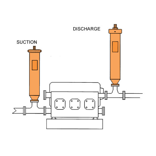
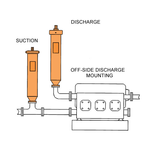
The most common type of pulsation dampener is a hydro-pneumatic pressure vessel containing compressed air or nitrogen and a bladder—or bellows—that separate the process fluid from the gas charge. To maximize the dampening effect, pulsation dampeners should be installed as close as possible to the pump discharge with a gas charge that is slightly below the normal system pressure. More important, pulsation dampeners must be properly sized for the system.
A dampener that is undersized cannot adequately compensate for pressure and flow fluctuations. An oversized dampener will act as an accumulator, storing too much fluid. This will cause slow stabilization and a delayed response to system changes. The first step in sizing a dampener is to quantitatively define the acceptable performance.
The specific requirements of the application and the components that make up the system are all factors that need to be considered. Once an acceptable pressure variation is defined, the unit size required for the desired performance should be determined. Engineers and designers are interested in making accurate predictions. Avoiding a problem is better than finding a way to fix it.
Sizing pulsation dampeners is straightforward. However, calculating the system pressure fluctuations is more complex. Fluid discharge rates from pumps are difficult to mathematically model. For example, in Figure 1, the spikes are not even. Theoretically, they should be equal. Mathematical models must be physically tested to verify their accuracy.
Pumps with multiple heads and higher pulse frequencies can make the calculations more difficult. The distance from one output port to the next is generally not constant. This creates a shift in the piston overlap with intermittent larger and smaller pulses. Calculating the magnitude or frequency of noise pulses that can develop or resonate in a system is difficult.
Piping arrangement—such as bends, reducers and valves—combined with the opening and closing of pump discharge check valves can create noise in the fluid called pressure pulses. Because many variables must be considered, each pump type should be tested with and without a dampener. The pressure curve data can be recorded and used to find the pump’s formula constant. This constant can be used in future calculations. As long as other pump models are similar to the test unit, accurately predicting the magnitude of line pressure variation with a given size dampener is possible.
The pressure in a piping system will rise sharply when a volume of fluid is added to the line. It accelerates the mass of the fluid in the piping system. This is acceleration head, and it needs to be minimized with a dampener. The effect and its impact must be considered on both the inlets and outlets of positive displacement pumps. On the inlet side, cavitation and partial filling of pump cavities can damage pump components and make the pump much louder than normal.
Bourdon tube gauges require time to equalize and can undershoot and overshoot the actual pressure depending on the magnitude and frequency of the pressure pulse. Even if the gauge could read accurately, reading a quickly moving dial is difficult. Electronically measured and recorded data can determine how the system is operating.
System noise must be considered when taking measurements because it can give higher-than-expected results. Noise in the pumping liquid can generally be ignored, but in some situations, system noise needs to be controlled. Noise can cause pressure relief valves to leak, damage sensitive components and create occupational safety hazards. Dampeners typically reduce noise, and some are specifically designed for this purpose.
Several different styles of dampeners are available, and each has advantages and disadvantages. This article focuses on reducing the pressure pulses caused by pulsing flow. The principles and the method for calculating the appropriate size dampener for this application are the same for most dampeners.
A dampener absorbs a fluid pulse and then allows the fluid to flow back into the system between pulses. Most dampeners use a gas charge that is set slightly below the normal system pressure and is compressed by the pulse of fluid. The gas then expands when fluid is released.
In this formula, n is a constant that is specific to the gas being used. For example, for air at room temperature, n ≅ 1.4, and for nitrogen, n ≅ 1.399.
Some heat transfer almost always occurs. The process is rarely slow enough for the gas temperature to equalize, so the actual answer will be between these two calculations. In most cases, the fluctuations are fast enough that the actual value is significantly closer to the isentropic formula. The isentropic formula gives the most conservative result. Therefore, it is the more accurate formula in most cases.
In actual practice, either formula would probably work if the pressure fluctuations are small relative to the system pressure. The pump constant that is developed would cover the inaccuracies in the formula as long as the pressure variations are similar. In this article, the isentropic formula is used.
To determine the pump constant, the volume from a single pulse of the pump must first be determined. Then an initial estimate of dampener size is made, and the corresponding value of dampener volume is applied. The amount of gas in the dampener will be less than the total dampener volume, which needs to be factored into the calculation. A typical range of 80 to 90 percent of the dampener volume should be gas if the dampener is properly charged. These give an initial gas volume:
The constant reduces the pulse volume to account for flow leaving the dampener while the pulse is entering. It also accounts for piston overlap, which changes the effective size of the pulse. Adding the factor to the isentropic formula and solving for the pump factor gives us the following equation:
For example, the pressure curve from an undampened, two-shoe, 2.5-inch peristaltic hose pump shows a sharp increase in flow, followed by a “no-flow” or negative flow zone. In this instance, the line has a ball valve that is creating the flow restriction for back pressure. The blue line shows the undampened pressure spikes (see Figure 2). The red line shows the pressure changes of the same pump with the same back pressure valve setting but now using a dampener. This sample dampener has an actual gas volume of 415 cubic inches, and the dampener is 90-percent gas filled. The base pressure is 14.15 psig, and the pulse is 76.9 cubic inches. If the pressure fluctuation is calculated using the isentropic pressure formula, the result is:
It is important to remember to add 14.7 psi to convert from gauge to absolute pressure, then subtract 14.7 psi again to get the final result in gauge pressure. This pump setup was tested, and the actual pressure variation was determined to be 7.38 psi. Therefore, the result is:
If the example above is used and it is decided that a pressure fluctuation of 15 psi would be acceptable, the formula with the previously calculated pump factor can be used to determine what size of dampener is needed.
Table 1 lists some approximate pump constant factors that can be used when sizing dampeners for different pump types. These factors are approximate, and the results may vary significantly with the many variables involved.
A triplex plunger pump doses methanol, which is metered on the discharge side. Without a dampener to control pulsations and smooth out the flow, the installed flow meters were giving inaccurate readings.
When using a triplex pump, all three chambers of the pump must stay full of fluid with no voids. Any voids or pockets can cause seal leakage, pump vibration and excess pump noise.
The solution was to install a pulsation dampener at the pump discharge to smooth the flow and remove pressure pulsations. This allowed the dosing to be more accurate. An inlet stabilizer (suction dampener) was also installed on the inlet side of the pump to act as an accumulator to keep the pump chambers filled. The inlet stabilizer also removed pulsations created by the pump on its inlet stroke. Both devices were sized based on the pump type, flow rate and operating pressure.
During the filling of a drum with a flexible hose, an automatic valve would close and cause a water hammer effect. All the pipes leading into the system would shake until they broke loose from their supports. The solution was to install a pulsation dampener at the beginning of the flexible hose connection.
The pulsation dampener was sized based on the flow parameters and installed at the beginning of the flexible hose. When the automatic valve closed, the hose and pulsation dampener effectively absorbed a portion of the water hammer, eliminating pipe shake and improving operational safety.
The sizing of a pulsation dampener is critical to achieving the desired result. Finding and using the correct constant pump factor in dampener sizing is a key part of the solution. As long as the pulsation dampener is properly sized, positioned and charged, it will effectively dampen pulsations to protect equipment and keep the pressure pulses within design parameters.
Pulsation dampeners (also called pulsation dampers) are used for stabilizing the flow and the pressure in circuits with volumetric or dosing pumps. They are used in a wide range of applications.
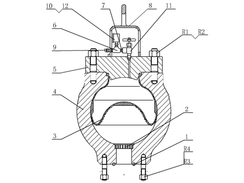
In every pulsation dampener there is a separator element between the gas it is charged with and the liquid of the circuit; its basic function being to avoid the leaking of the gas into the circuit. This separator element is basically made of two kinds of materials: Rubber (NBR, EPDM, FPM, butyl, silicone, etc…) or a thermoplastic material (normally PTFE); although it can also be made in stainless steel.
When a rubber separator element is used, the dampener is called bladder type. If the material is PTFE, we refer to membrane type and bellows type dampeners, depending on the shape of the separator element.
Choosing between different types of dampener depends on characteristics of the circuit like working pressure, temperature and chemical compatibility between the liquid and the material of the separator.
All our pulsation dampenersare made according to the European PED97/23/CE pressure vessels regulations, and their design meets the AD-2000 and ASME VIII Div.1 & 8 codes requirements (“U” stamp pending).
We can supply all of our dampeners with different circuit connection gauges as well as fitted with whatever flange, either screwed on, welded or integrated, to suit the customer’s needs.

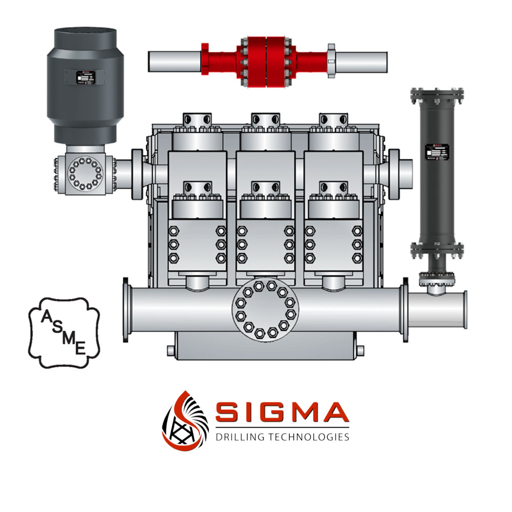
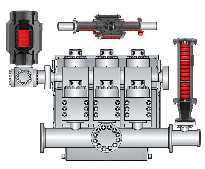
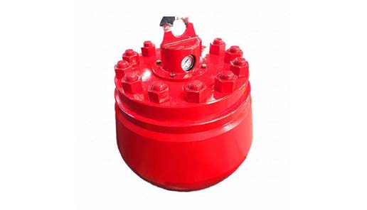
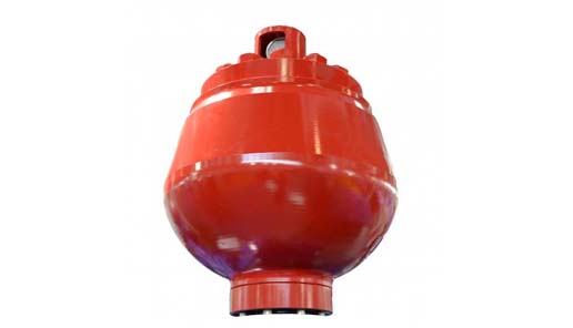
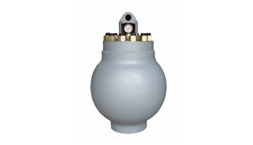
Mud Pump Pulsation Dampener is usually installed on the discharge line to reduce the fluctuation of pressure and displacement of the drilling mud pump.
Mud Pump Pulsation Dampener is a pneumatic device built into the outflow line of each UUD pump to dampen the pressure fluctuations resulting from the action of the pump. Although presented as a surge tank, this device is really a device that can be tuned to greatly diminish the output pulsations transmitted downstream from the mud pump. Unfortunately, the effectiveness of the pulsation dampener is a function of both output pump pressure and frequency of the pump pulsations.
Manufacturer and distributor of noise and sound control products. Acoustical and noise control products include acoustic tiles, ceiling tiles, sound barriers, acoustical wall coverings, foam panels, wedges, curtains, blankets, baffles and enclosures. Materials include melamine and polyurethane foam, PVC vinyl and fiberglass. Noise absorbers are suitable for use in industrial applications, TV/radio, kennels, churches, music studios, gymnasiums, commercial offices, phone booths and HVAC. Capabilities include assistance in diagnosing acoustical problems and identifying the correct material for specific projects. ASTM compliant.
Drilling consumables such as mud pump systems and their components can drastically increase your uptime while reducing costs and health/safety/environmental (HSE) risks. To support your drilling needs, Forum’s patented P-Quip® mud pump system offers a single-source solution that integrates high-quality fluid end components for maximum longevity and performance.
With more than 20 years of successful operation in severe environments, P-Quip offers a proven track record for the lowest cost of ownership in the industry. As part of our commitment to quality, our mud pump parts use patented Banded Bore™ technology that significantly reduces stress concentrations and leads to longer module life.
One of Forum’s most committed core values is that “no one gets hurt,” and the P-Quip system is designed to support that principle. Streamlined and easy to use, it reduces or eliminates the need for manual force during maintenance, shrinking the time needed to replace high-use components and minimizing safety risks.
Since the NOV A1700-PT Triplex Mud Pump was built approximately 60 years ago, the industry has widely accepted the three cylinder or triplex style pump. Triplex mud pumps are manufactured worldwide, and many companies have emulated the original design and developed an improved form of the triplex pump in the past decade.
NOV A1700-PT Triplex Mud Pumps have many advantages they weight 30% less than a duplex of equal horsepower or kilowatts. The lighter weight parts are easier to handle and therefore easier to maintain. The other advantages include;They cost less to operate
One of the more important advantages of triplex over duplex pumps, is that they can move large volumes of mud at the higher pressure is required for modern deep hole drilling.
NOV A1700-PT Triplex Mud Pump is gradually phasing out duplex units. In a triplex pump, the pistons discharge mud only when they move forward in the liner. Then, when they moved back they draw in mud on the same side of the piston. Because of this, they are also called “single acting.” Single acting triplex pumps, pump mud at a relatively high speeds. NOV A1700-PT Triplex Mud Pump has three pistons each moving in its own liner. It also has three intake valves and three discharge valves. It also has a pulsation dampener in the discharge line.
The Penn Valley pump is a diaphragm pump. Penn Valley has acknowledged this in their patent # US 7,559,753B2, where they reference application # GB 2013287ADiaphragm pump as the basis of construction. Also Penn Valley’s application with the trademark office also reference diaphragm pumps.
TechnologyPositive displacement reciprocating diaphragm pump per ANSI/HI standardsPositive displacement reciprocating diaphragm pump per ANSI/HI standards
Principle of OperationPositive displacement pump using reciprocating motion and check valves to displace liquid from suction to discharge side of pumpPositive displacement pump using reciprocating motion and check valves to displace liquid from suction to discharge side of pump
TrunnionSealing device that flexes with the mechanical reciprocating motion to seal liquid within pump bodySealing device that flexes with the mechanical reciprocating motion to seal liquid within pump body
Pumping ActionReciprocating pumping with extended stroke length operating at low speed. Stroke length and speeds are directly proportional in positive displacement pumps
All reciprocating pumps create pulsing flows and use pulsation dampeners to reduce pulsationShort stroke length requires very high speeds to achieve same flow rate
Base FrameHeavy-duty fabricated steel channel with supporting pedestal feet for direct mounting to floor (optional 304SS foot base)304SS lightweight tube frame with pedestal feet
Wastecorp is an ISO 9001 and ISO 14001 certified pump manufacturer with decades of positive displacement pump experience in the municipal and industrial sectors. Wastecorp’s North American based manufacturing facilities make a diverse range of high quality pumps primarily used for wastewater fluid transfer applications. The company specializes in sewage pump and wastewater pump manufacturing. This includes multiple products for municipal/industrial applications. Information about Sludge Pro Double Disc Pumps can be found here.
Wastecorp, Penn Valley and others are categorized as a reciprocating positive displacement mechanical diaphragm pump as defined by the American National Standards Institute/Hydraulic Institute Standards, who is the recognized global authority of pump guidelines and standards.
Wastecorp uses this terminology to distinguish the large disc used in the Sludge Pro’s patented pump design. The disc is the main element that transfers the liquid in conjunction with the check valves. The trunnion is the flexible seal that ensures a leak free design. The robust design has an excellent track record of long term durability and trunnions are engineered to last millions of cycles.
Yes. Wastecorp can send parts for your double disc pump for delivery within 24 hours in most areas of the United States and Canada. In select areas, Sludge Pro parts are stocked in the State/Province or county that the pumps are located in.
A pulsation damper is an equipment capable of playing a very important role in the use of double diaphragm pumps. As can be seen from the name, this accessory is aimed at reducing pulsations and vibrations during pump operation, thus ensuring a “continuous” and precisely non-pulsed flow rate and a reduction of vibrations on the system pipes.
A pulsation damper works thanks to the same compressed air that feeds the pump. The compressed air introduced into the counter-pressure chamber behind the membrane creates a pneumatic damping cushion that self-adjusts according to the stress exerted by the pressure pulse of the fluid generated by the pump.
EQUAFLUX dampers are used with fluids of high apparent viscosity even in the presence of solid parts in suspension. They automatically adapt to the system conditions, without manual adjustment or calibration. The high ability to minimize pulsations, vibrations and water hammers makes this component a suitable equipment for safeguarding the system, giving regularity to the outgoing flow. The wide choice of construction materials allows you to determine the best chemical compatibility with the fluid and / or the environment without neglecting the correct temperature range. The dampers are also available for use in a potentially explosive environment (ATEX certification).
Inside the hydraulic systems, the pulsations of the fluid can cause phenomena called water hammer consisting of pressure peaks caused by a sudden change in the flow rate inside the pipes or by the sudden closure of a valve. The effects of water hammer vary according to the size of the pipeline and the speed and density of the fluid but can often cause extensive damage to the elements of a system. To preserve the system from water hammer and vibrations, it is possible to use the pulsation dampers of the Equaflux series that can automatically adapt to the operating conditions of the pump.
Equaflux pulsation dampers are normally applied to pneumatic double diaphragm pumps. The latter, during the phases of use, can record pressure peaks which, if not controlled, can damage the elements of a system. The main benefits associated with the use of pulsation dampers can be summarized in the following points.
The application of diaphragm pumps equipped with pulsation dampers refer to the entire process industry: hydraulic systems, use in chemical transformation processes, use within the petrochemical, mining sectors and much more. The EQUAFLUX series is also available with ATEX certification and therefore can be used directly within sectors with the presence of explosive risks.
Pulsation dampers are very versatile tools whose use can vary according to the needs of the operating processes and application sectors. For this reason, a sales team is at your disposal to support you in choosing the most suitable configuration for your needs. Contact the Debem team now.
Our custom-designed systems will absorb excess energy pulsing through the pump and piping system by creating a low-pressure area to dampen the excess shocks and vibrations. Because a pulsation dampener regulates the release of energy, your system will be better protected and run more smoothly. After installing a pulsation dampener, customers notice that their system:
When you choose to work with our team, we’ll help you find the right specifications across our product series, allowing us to customize features, including:


 8613371530291