
interchangeable mud pump part free sample
Mud-Pump Gear Sets . . . . . . . . . . . . . . . . . . . . . . . . . . . . . . . . . . . . . . . . . . . . . . . . . . . . . . . . . . . . . . . . . 13
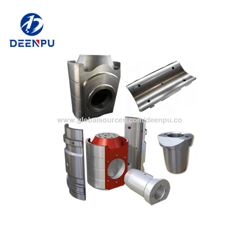
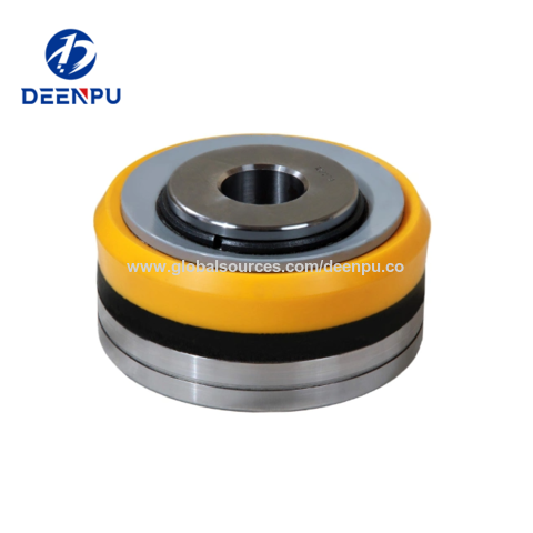
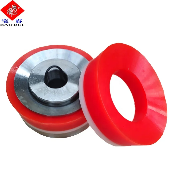
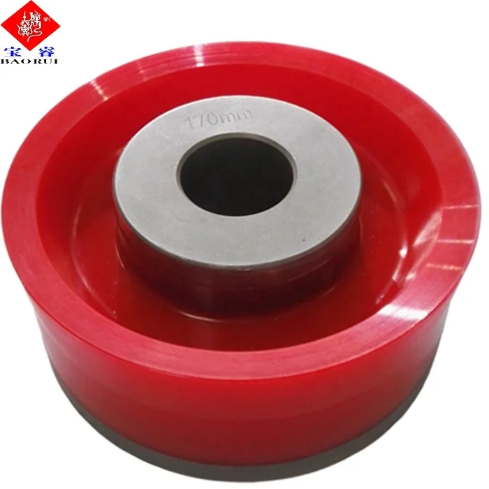
High chrome sleeve liners, zirconia ceramic liners, urethane bonded pistons with long service life, high temperature urethane bonded pistons, replaceable rubber pistons, rubber bonded pistons, a full range of full open, 3 web, 4 web and plate type design valves and seats available in API 4 thru 8 sizes to fit all major mud pumps, a complete line of interchangeable fluid end modules and accessories, for various OEM"s mud pumps such as National, Emsco, Gardner Denver, Bomco, Ideco and Oilwell etc.
The Liberty Process LL8 Progressive Cavity Pump is ideal for abrasive pumping applications such as drilling fluids with sand and grit common in fracking operations. As a Mud Pump, the LL8 Series is a popular model on many mobile pumping rigs in use today. Replacement mud pump parts are available as well from our stock and work on other popular manufacturers models.
LL8 parts are direct drop in aftermarket replacements that work with the *Moyno® L8 series, the *Tarby® TL8 series and *Continental® CL8 Series*. The Liberty unit is a low-cost, maintenance free, dependable drop-in replacement progressive cavity unit.
The Liberty LL8 is a standard flanged pump design manufactured with cast iron or 316 stainless steel pump casings designed in 1, 2, and 3 stages for 75, 150 and 225 psi discharge pressures and a flow rate of 18 up to 100 GPM.
The LL8 is a modular design with simple hardened pinned joint drive assembly. LL8 Rotors are typically hardened tool steel or 316 stainless steel with a hard chrome plating for long life in abrasive pumping applications.
All other wetted parts are either carbon steel or 316 stainless steel. Stators are available in many elastomer materials such as Buna Nitrile, Natural Rubber, EPDM and Viton. The standard seal design is a set of gland packing with a lantern ring set and flush connections. Mechanical seal options for this progressive cavity pump are readily available.
The LL8 represents one of the most popular progressive cavity pumps available for the transport of drilling mud with easily replaceable in-stock parts.

FET manufactures a full range of valves and seats for every drilling and well-servicing application as part of our full line of Osprey® mud pump system solutions. All of our valves and seats can be used in water, water base, oil base and synthetic base mud applications. FET offers additional valves and seats not listed below, including drilling valves, frac valves and well service valves. FET’s QC standards for the dimensional and material specs are extremely rigid in comparison to other manufacturers. Contact your FET representative to learn more.
Heretofore it has been customary for others to flow connect the entire drilling mud flow stream from the borehole to a flow divider apparatus which separates the major flow stream into several flow paths so as to greatly reduce the volume of the drilling mud or chip bearing flow stream which is to be treated for subsequent analysis. Often the flow is improperly divided due to the physical characteristics of the solids and the mechanics of the flow divider, all of which results in inaccurate analysis of the borehole for the reason that one divided flow stream differs in composition or mixture from another divided flow stream. After the mud sample has been reduced in volume by selecting one of the flow streams for analysis, it is necessary to permit the solids to settle by gravity, after which the clarified water is siphoned off or decanted, and the remaining saturated solids or residue heated to evaporate the liquid therefrom.
It is therefore desirable to be able to split a stream of drilling mud containing samples from the chip drilling process into any desired fraction of the main flow stream wherein the smaller fraction of the main flow is identical in composition or mixture to the remainder of the flow. It is also desirable to be able to treat this fraction of flow in an improved manner which removes the solids therefrom, and to be able to relate the retrieved solid samples to the particular depth of the borehole from which the sample originated.
This invention relates to formation chip sampling method for separating solids from drilling mud which may be obtained from an earth boring operation so as to enable subsequent analysis thereof. As the drilling mud flows from the borehole, it exits at the swivel and flows to a separator where the air is removed therefrom. From the separator the flow continues to a splitter where a fraction of the flow is separated from the main flow. The fractional flow continues to a reservoir with the reservoir having fluid level control means associated therewith for supplying makeup water thereto in order to always maintain a fluid level therein. The contents of the reservoir is pumped under a positive pressure to a cyclone separator. The pump flow and the physical dimensions of the cyclone separator are sized with respect to one another so as to provide an optimum separation of solids from the liquid at the cyclone separator. Where deemed desirable, and especially when utilizing the chip drilling process, a screen may be interposed between the splitter means and the reservoir so as to reduce the load on the pump while at the same time maintaining large chips in an undamaged condition which will enhance the subsequent analysis thereof. The screened solids are combined with the solids removed from the cyclone separator and placed in a suitable container for storage or shipment.
A still further object of the present invention is the provision of a method by which formation chip samples are obtained from a chip drilling operation by improvements in separating solids from the drilling mud.
A still further object of the present invention is the provision of formation chip sampling methods which removes air from drilling mud, separates the drilling mud flow stream into a fractional part wherein the fractional part contains solids which are representative of the solids contained within the main flow stream, and which separates the solids from the liquid of the fractional component of the main stream.
Still another object of the present invention is a method of removing solids from drilling mud so as to provide a formation chip sample which can be related to the particular depth of borehole from which the sample originated.
FIG. 1 is a part diagrammatical, part schematical representation in the form of a flow sheet which describes the essence of the method of the present invention;
FIG. 6 is a part diagrammatical, part schematical representation in the form of a flow sheet which describes another embodiment of the present invention;
FIG. 8 is a reduced top plan view of a part of the apparatus disclosed in FIG. 6, with some parts thereof being broken away therefrom in order to better disclose the invention.
As seen in the diagrammatical representation of FIG. 1, the present invention is used in conjunction with a borehole forming operation, broadly indicated by the arrow at numeral 10, wherein there is seen concentrically arranged drill pipe extending into the ground with the upper terminal end thereof being connected to a swivel 12. Drilling fluid, or drilling mud is pumped to the swivel in the usual manner while drilling fluid containing chips and particles of the formation being penetrated are retrieved at gooseneck 16. The gooseneck is flow connected to tangential inlet 17 of air separator means 18. The air separator has an upwardly depending centrally located conduit 19 from which air escapes. The air-free liquid flows through bottom outlet 20 and is directed into a splitter means 21.
The splitter includes a large outlet 22 which is flow connected to mud pit 23 by any suitable means, and to which the major portion of the flow is conducted. Small outlet 24 receives the remaining fraction of the drilling mud which is originally returned from the borehole. The remaining portion or fraction of the mud flows through screen 25 in order to remove large particles or chips therefrom. The fraction of the drill fluid which includes the smaller cuttings or particles which were not retained by the screen continues to flow on to the reservoir at 26. The upwardly opening reservoir has a sloped bottom to which a lower outlet is flow connected to pump means 27.
The pump can be actuated by any suitable means, as for example, a gasoline motor. The pump provides a high pressure flow to tangential inlet 28 of cyclone separator 29. As the drilling fluid flows through the cyclone separator, the liquid is separated from the remaining solids contained therein, with the liquid finally exiting at 30 where it can be flow connected to any suitable disposal means, as for example, the mud pit, while solids fall through lower outlet 31 where they are retrieved within any suitable receptacle 32. A source of makeup water (not shown) is connected to valve means 33 which in turn is controllably flow connected to a journaled float means 34 by the illustrated linkage. The float and valve assembly provides a level controller device for controlling the flow of make-up water into the reservoir so as to maintain a suction for the pump at all times.
FIGS. 2 and 3 show the details of the separator apparatus which includes a gear driven pump 27 having rubber impellers thereon and which is capable of producing a flow rate and pressure consistent with the design of cyclone separator 29 and to the mud flow rate into the reservoir.
The pump is driven by an internal combustion gasoline motor of the following described type: Wisconsin Engine, 3 × 31/4 size. The pump is of the following described type: gear driven, rubber impellers, capable of 40 g.p.m. at 9-15 p.s.i.g., manufactured by Booie. The inlet of the cyclone separator is provided with 40 g.p.m. flow rate. The separator is available from Kerbs Engineering, 1205 Crysler Drive, Menlo Park, California, Model D4B-12.
Looking now to the details of FIGS. 4 and 5, the before mentioned air separator 18 is seen to be in the form of a cylindrical tub having tangential inlet 17 connected to an upper extremity of the sidewall thereof; and with an upwardly depending reduced diameter air outlet 19 being provided at the upper end thereof. Outlet 20 is in the form of a downwardly and outwardly directed elbow which is arranged in overhanging relationship with respect to the splitter so as to cause the mud flowing therefrom to impinge against the rotating vanes of the splitter, as will be pointed out in greater detail later on.
The splitter has an upwardly opening interior as indicated by the arrow at numeral 35 which is formed by the stator of fixed tub portion 36. Within the stator there is rotatably disposed a rotor comprised of cylinder 37 having a multiplicity of radially disposed vanes 38 which rigidly connect the cylinder to a tubular element 39. The tubular element is rigidly affixed to a shaft 40 with the shaft having spaced apart bearings 41, 42, each of which are located at the upper and lower extremity of the shaft so as to rotatably support the shaft from the fixed members 43 and 44. Tubular member 39 is received within the upwardly opening complementary fixed tubular member 45. Inwardly sloped floor members 46, 48 are affixed between adjacent vanes and form spaced apart catch basins between some of the vanes, with the lower extremity of the basins being apertured as seen at 49 so as to communicate the interior of the complementary fixed tubular member therewith.
A pair of spaced apart rails 51 underlie the trough 24 and provides a support means for the before mentioned screen so as to enable the screen to be conveniently interposed between small outlet 24 and the reservoir. While the particular embodiment disclosed herein illustrates each sixth area as being a basin it is preferred that each fourth area between adjacent vanes be provided with a lower bulkhead or floor so as to provide the before mentioned split of 25 percent of the flow. Alternatively, othe rsplits may be achieved by merely varying the number of floor members employed within the rotor.
In the embodiment set forth in FIGS. 6-8, the numerals used in conjunction therewith refer to similar numerals used in conjunction with FIGS. 1-5, wherever possible. As seen in FIGS. 6-8, mud from the drilling operation flows through air separator 118, which may be identical to the air separator of FIGS. 1-5. A screen 125 is interposed between the air separator liquid outlet 120 and the entrance of hopper or reservoir 126. The upper edge portion of the reservoir forms a support for the frame of the screen.
Valve 133 is actuated by float level device 134 in a manner similar to the arrangement of the level controller disclosed in FIGS. 1-5. Outlet 160 is connected to a bypass "T" 161, with the "T" having the illustrated valve therein for flowing mud to the mud pit. Valve 162 connects the "T" to pump 127, which in turn is connected to inlet 128 of separator means 129.
The liquid outlet 130 is freely received within the inlet elbow 163 of storage tank 165 with the outer peripheral wall surface of the outlet being spaced apart from the inner peripheral wall surface of the elbow. Overflow 164 can be flow connected to the mud pit, and is located below the inlet of the elbow so as to maintain the liquid height within the tank at a level which always leaves room for liquid flow from the separator. Outlet 166 is flow connected to the valve 133 of the liquid level control means.
In operation, drilling mud is circulated from a main mud pump (not shown), to the swivel where it is forced through the drill string annulus downhole to the drill bit, and back through the central passageway to the inlet 17 of the air separator. The formation samples cut by the action of the bit are in the form of chips and cuttings, and are transported by the drilling fluid into the air separator 18. The air separator can take on several different forms but preferably is similar to a centrifuge in that a vortex is established by the tangental inlet 17, thereby causing the drilling fluid to be separated from air contained therewithin. The air separator is especially useful where the chip drilling process is supplemented with air drilling, but is not considered indispensable to the process. As drilling mud exits from outlet 20, it impinges against the vertically disposed radiating vanes of the splitter, causing a rotational motion to be imparted into the rotor. Since the rotor is spaced apart from the wall of the stator and journaled at its upper and lower extremity, it will rotate at a r.p.m. or with a peripheral velocity which is dependent upon the flow rate of the drilling mud received therewithin. The major portion of the mud flow stream is free to flow through the spaced apart vanes at 47" and to the outlet 22, while a smaller fraction thereof is intercepted by the catch basins formed by the floor members 48.
As the mud flows through the spaced apart vanes 38, that is, the adjacent vanes which have no floor therebetween, it continues on through the rotor and into the lower extremity of the tub or stator where it then flows through outlet 22 and is directed to the mud pit 23. The smaller fraction of the drilling mud which flows into the catch basin, however, is trapped by the floor member and diverted through aperture 49, into the rotatable tubular member, and into fixed tubular member 45, where it then flows from lower chamber 50 and through outlet 24.
The number of catch basins 48 may be varied to provide any split desired, as for example, one sixty-fourth or one-half of the total returned mud flow may be deemed desirable as a feed rate into the reservoir 26. The number of catch basins determines the formation sample size as well as the load placed on the screen, reservoir, pump, and cyclone.
Trough 24 preferably is arranged in overhanging relationship with respect to reservoir 26 so as to enable fluid therefrom to flow by gravity thereinto. Screen 25 is preferably of 60 mesh size and is interposed between trough 24 and the reservoir by merely resting the edge portions of the screen on the spaced apart support members 51 as generally indicated by the arrow at numeral 25".
Since most chip drilling operations employ a fluid circulation rate of about 140 gallons per minute when making a 41/2 inch diameter hole, it is evident that the fraction of this amount which will be divided out by the splitter and received within the reservoir is dependent upon the ratio of catch basins to the open vanes. Since the pump 27 preferably receives exactly 40 gallons per minute, and assuming a 25 percent split, it is evident that the float 34 must open valve 33 a sufficient amount to supply 5 gallons of fresh make-up water per minute in order to maintain a fluid level within the reservoir.
Pump 27 delivers a constant flow of fluid to the cyclone separator, which can take on several different forms, and preferably is essentially a vertical cylinder with the usual inlet stream 28 being introduced tangentally near the top so as to give a spinning motion to the liquid traveling therethrough. The centrifugal force acting on the suspended solids tends to throw them radially to the side of the cyclone as the solids spiral downward to the conical bottom where they are removed at 31. The separated liquid is disposed of at the top, with the conduit 30 being a conventional outlet. With the cyclone separator operating within its most efficient range, essentially no liquid is lost through the solids outlet, and essentially saturated solids drop into the receptacle 32. It is for this reason that the pump 27 must always operate within its most efficient range, or otherwise the operation of the cyclone will not produce this desired effect.
The sample attained at 32 is related to the borehole depth by changing the screen 25 and receptacle 32 each five foot of hole, although other increments of penetration may be used where deemed desirable. Since the splitter divides out any desired portion of the returned mud, and since the divided portion of the flow stream is identical in composition to the remainder thereof, the present invention provides formation samples which are more representative of the strata being penetrated than has heretofore been possible to attain. All of the suspended solids passing the screen 25 are effectively separated from the liquid in a manner which obviates the necessity of decantation and evaporation treatment as has heretofore been necessary with prior art devices. By utilizing the present invention, each time the screen and receptacle is changed for the next five foot sample, it is now possible to immediately bag the obtained core sample and send it to the geologist. Accordingly, possible contamination of the sample is avoided since it is exposed a minimum length of time to the elements. This also avoids inadvertent interchange or mix-up of the samples.
In carrying out the invention in accordance with the embodiment disclosed in FIGS. 6-7, the large cuttings are obtained on screen 125 and combined with th centrifuged solids obtained at 132. The use of a splitter downstream of air separator 118 is considered optional, depending upon the flow rates involved. While making hole through known strata, the valve at 161 can be opened, while valve 162 is closed, so as to flow all of the mud to the mud pit, thereby leaving the pump and centrifuge inactive until they are needed.
When a mineral bearing strata is encountered, the valve at 161 is closed, the valve at 162 opened, and circulation through pump 127 initiated. Mud now flows into the air separator, through the screen, and into the reservoir. Make-up water flows from 166, 133 and through tangential inlet 167 where the side walls of the reservoir are cleaned of cuttings. The float at 134 maintains a fluid level within the reservoir which enables the pump to provide the separator means with a constant flow so as to achieve optimum efficiency of separation.
Since the overflow pipe 164 is located below the inlet elbow, the storage tank will overflow to the mud pit without affecting the liquid flow from the separator. Outlet 166 provides a constant source of make-up water to valve 133. Since the solids have been removed from the drilling mud, the only contaminate which can be contained within the make-up liquid is dissolved minerals. The reuse of this liquid is preferred to using make-up water which can be obtained from the mud pit for the reason that insoluble minerals are not recirculated through the system. Moreover, soluble minerals will be solublized at a slower rate as the recirculated make-up water dissolves a particular soluble element.
The present invention provides a method of obtaining formation chip samples which permits both a qualitative as well as a quantitative analysis to be achieved since the weight percent of any material obtained in a formation chip sample can be directly related to the total amount of material removed from the borehole. This aspect of the invention is particularly important relative to ores such as copper and molybdenum, for example, since the economical breaking point of molybdenum is at about 0.5 percent, and accordingly 0.1 percent accuracy is very important when making a chemical analysis of the formation chip sample in order to determine the economics of sinking a mine shaft.
The specific splitter means together with the cyclone separator used herein is indespensible for handling ores which tend to float due to their surface tension and particle size. Material of this nature would otherwise be lost because they would float off to the mud pit in the absence of the present method.
While a particular pump and cyclone separator have been disclosed herein for purposes of illustration, it is pointed out that other pumps and other types of cyclone separators or centrifuge means may be used so long as the inlet pressure and flow rate to the cyclone separator is maintained within a range which prevents liquid from falling from the separator into the receptacle, and so long as carry-over of solids into the discharge is avoided.

Spectra offers two fantastic breast pumps – the S1 and the S2. What are the differences, and which one is right for you? Here are the features of each pump, and what you need to know to choose between the two Spectra breast pumps.
Buying a breast pump – especially if you are planning on exclusively pumping – is a huge commitment, and kind of nerve-wracking. You’re going to be spending two hours a day hooked up to your pump, but often you have to buy it without trying it out or seeing it in person.
The S1 and S2 Spectra models are double electric breast pumps. (A “double” pump means that you can pump both breasts at the same time when using it. If you’d like to pump on just one side, it’s possible to set it up to do that, too.)
The three biggest advantages to Spectra pumps cited by users that I interviewed in the Facebook group were comfort, noise level, and customer service.
These two pumps are a little bigger and less portable than some of the other pumps on the market. However, those smaller pumps (like the Freestyle Flex or the Willow) are often much more expensive.
However, Idaho Jones does make a pump belt that you can use to “wear” your Spectra and be more mobile. (It’s basically a fanny pack that’s designed to hold your pump.) You can check it out here and use the code EPUMP10 for 10% off!
The only other thing I would say is that depending on where you live, it may be challenging to go to the store and pick up replacement parts in an emergency (if yours break or you lose a piece). You may want to stock up on extra parts to avoid issues with this.
The S2 is more equivalent to the Medela Pump in Style, given the need for an outlet. Here is a detailed comparison of the pros and cons of the Pump in Style and the Spectra S2.
If you’re buying your breast pump out of pocket, the Medela pumps are generally at a higher price point than the Spectra pumps. The exact prices fluctuate but generally the Medela pumps are $40-$80 more than the comparable Spectra pumps.
This can be useful if you want to continue to use your old pump parts versus buying all new sets, or if you prefer Medela pump parts. (Some people prefer pump parts with a separate flange and connector – it can make using a hands-free pumping bra easier, for example.)
Having a rechargeable battery makes life so much easier – especially if you’re exclusively pumping or will need to move around when you pump. Therefore, I’d highly recommend choosing the S1 if your budget allows.
If your insurance only covers an S2, check and see if they offer the option to upgrade. Some insurance companies offer basic pumps free through insurance, as well as the ability to pay the price difference between the basic pump and an upgraded pump.

The 2,200-hp mud pump for offshore applications is a single-acting reciprocating triplex mud pump designed for high fluid flow rates, even at low operating speeds, and with a long stroke design. These features reduce the number of load reversals in critical components and increase the life of fluid end parts.
The pump’s critical components are strategically placed to make maintenance and inspection far easier and safer. The two-piece, quick-release piston rod lets you remove the piston without disturbing the liner, minimizing downtime when you’re replacing fluid parts.

A wide variety of drill mud pump part options are available to you, such as 1 year, not available and 2 years.You can also choose from new, drill mud pump part,As well as from energy & mining, construction works , and machinery repair shops. and whether drill mud pump part is 1.5 years, 6 months, or unavailable.


 8613371530291