
kirloskar mud pump free sample
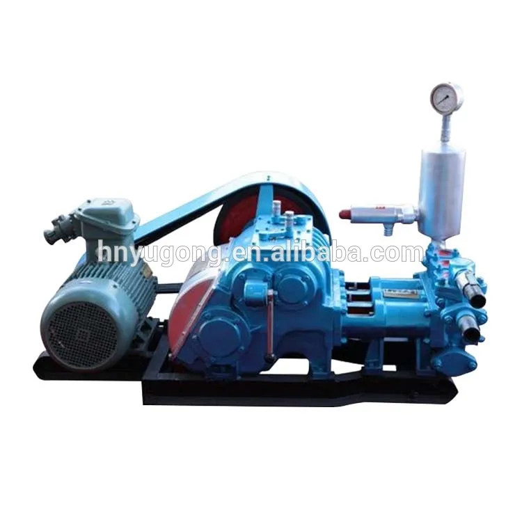
Explore a wide variety of kirloskar pump on Alibaba.com and enjoy exquisite deals. The machines help maintain drilling mud circulation throughout the project. There are many models and brands available, each with outstanding value. These kirloskar pump are efficient, durable, and completely waterproof. They are designed to lift water and mud with efficiency without using much energy or taking a lot of space.
The primary advantage of these kirloskar pump is that they can raise water from greater depths. With the fast-changing technology, purchase machines that come with the best technology for optimum results. They should be well adapted to the overall configuration of the installation to perform various operations. Hence, quality products are needed for more efficiency and enjoyment of the machines" full life expectancy.
Alibaba.com offers a wide selection of products with innovative features. The products are designed for a wide range of flow rates that differ by brand. They provide cost-effective options catering to different consumer needs. When choosing the right kirloskar pump for the drilling project, consider factors such as size, shape, and machine cost. More powerful tools are needed when dealing with large projects such as agriculture or irrigation.
Alibaba.com provides a wide range of kirloskar pump to suit different tastes and budgets. The site has a large assortment of products from major suppliers on the market. The products are made of durable materials to avoid corrosion and premature wear during operations. The range of products and brands on the site assures quality and good value for money.

Explore a wide variety of kirloskar slurry pump on Alibaba.com and enjoy exquisite deals. The machines help maintain drilling mud circulation throughout the project. There are many models and brands available, each with outstanding value. These kirloskar slurry pump are efficient, durable, and completely waterproof. They are designed to lift water and mud with efficiency without using much energy or taking a lot of space.
The primary advantage of these kirloskar slurry pump is that they can raise water from greater depths. With the fast-changing technology, purchase machines that come with the best technology for optimum results. They should be well adapted to the overall configuration of the installation to perform various operations. Hence, quality products are needed for more efficiency and enjoyment of the machines" full life expectancy.
Alibaba.com offers a wide selection of products with innovative features. The products are designed for a wide range of flow rates that differ by brand. They provide cost-effective options catering to different consumer needs. When choosing the right kirloskar slurry pump for the drilling project, consider factors such as size, shape, and machine cost. More powerful tools are needed when dealing with large projects such as agriculture or irrigation.
Alibaba.com provides a wide range of kirloskar slurry pump to suit different tastes and budgets. The site has a large assortment of products from major suppliers on the market. The products are made of durable materials to avoid corrosion and premature wear during operations. The range of products and brands on the site assures quality and good value for money.
Leading Wholesale Distributor of kirloskar dewatering mud pump, kirloskar self priming mud pump - bare pump, lubi dewatering mud pump and crompton dewatering mud pump from Mumbai.

Carrier Global Corporation, Thermax Limited., Kirloskar Pneumatic Company Ltd., Johnson Controls-Hitachi Air Conditioning, LG Electronics, Trane Technologies Company, LLC, ROBUR S.p.A, Others

We warrant that the pump supplied from us is free from defectivematerial and faulty workmanship. This warranty holds good for aperiod of 12 months from the date of commissioning theequipment or 18 months from the date of dispatch from ourfactory, whichever is earlier. Our liability in respect of anycomplaint is limited to replacing part/parts free of charge ex-worksor repairs of the defective part/parts only to the extent that suchreplacement/repairs are attributable or arise solely from faultyworkmanship or defective material.
3 N, NB, NM- 2 vanes enclosed impeller. 1. GENERAL: Q- 3 vanes semi open impeller. 1.1 “SHM” is a non-clog solid handling R- 8 vanes free-flow impeller. pump. SHM series of pumps are designed QP- 3 vanes semi open impeller (for paper to withstand arduous duty conditions stock application only). which normally every solid handling pump has to face on sites. 1.3 Pumps when properly installed and given due care in operation and SHM pumps are horizontal, single stage, maintenance should satisfactorily perform centrifugal, end suction, vertical delivery for a long period. pump with specially designed volute casings and impellers. 1.4 When the pump is received, it should be inspected before installation. If The complete series of SHM pumps with it is not installed immediately, it is to be delivery size ranging from 50 mm to 200 located in dry place. When not in actual mm covers a wide performance range. use, the pump shaft should be rotated once in a month to prevent pitting of 1.2 This booklet covers instructions for bearing surfaces. following types of SHM pump models with impeller types. 2. Safety Instructions:UNIT MODEL IMPELLER TYPE Enclosed Three Free 2.1 General Information Vane Flow Semi Before performing any actions Two Vane Single Vane Open detailed within this instruction, the HealthSHM- 50/26 N NB -- P Q -- R and Safety instructions shall be read and 7 50/32 N -- -- -- -- -- -- fully understood. The instructions in this 65/32 N NB -- P Q -- R 80/26 N -- -- P Q -- R document shall also be read and fullySHM- 80/40 N -- NM P Q -- -- understood. 9 100/26 N -- -- P Q -- R 100/32 N -- -- P Q QP R Whenever the equipment is 150/26 - NB -- -- -- -- -- NB operated, maintained or used in any way,SHM- 100/40 N -- -- P Q QP R the procedures detailed within the Health11 150/26 N -- NM P Q -- R and Safety Dossier and any procedures 150/32 N -- -- P Q -- R detailed within these instructions shall be 150/34 N -- -- -- -- -- -- 150/40 N -- -- -- Q -- R followed. Some hazards cannot be 200/32 N -- -- P Q -- R guarded against and the instructionsSHM- 150/50 N -- -- P Q -- --13 below MUST BE COMPLIED WITH for safe 200/40 N -- -- -- Q -- R operation. These instructions cannot cover all circumstances. It is the responsibility of Note: - Pumps with horizontal delivery are the user of the equipment for maintaining also available upon request. safe working practices at all times. Note: - A) the complete range of SHM 2.1.1 Kirloskar Brothers Limited (KBL) pumps is covered by four driving units, products are designed for installation in thereby reducing inventory and achieving designated areas, which are to be kept interchangeability of parts. clean and free of obstructions that may B) The above models can be offered with restrict safe access to the controls and following impellers. maintenance access points. P- Single vane enclosed impeller 4 Pump nameplate is fitted to each by KBL could result in bodily injury orunit and must not be removed. Loss of property damage.this plate could make identificationimpossible. This in turn could affect safety 2.5 Within the manual, safetyand cause difficulty in obtaining spare instructions are marked with safetyparts. Such accidental loss of nameplate symbols.or damage if occurs, contact KBLimmediately. Hazard.2.1.2 Access to the equipment shouldbe restricted to the personnel responsible This symbol refers tofor installation, operation and maintenance general mechanical aspects of safety.and they must be qualified, trainedadequately and supplied with theappropriate tools for their respective tasks. Hazard.
2.1.3 KBL firmly insists that allpersonnel responsible for installation, This symbol refers tooperation and maintenance of the electrical safety.equipment must read the manual beforeany work is done. 2.6 Transport, Handling and Storage Instructions:2.1.4 Ear defenders should be worn 2.6.1 Transport.where the specified equipment noise level Pumps are dispatched in dulyexceeds locally defined safe levels. Safety assembled condition. Lubricating oil in theglasses or goggles should be worn where bearing housing is drained prior toworking with pressurized systems and dispatch of pump if the pump is oilhazardous substances. Other personal lubricated. Pumps are protected againstprotection equipment must be worn, corrosion and packed for transport bywhere local rules apply. normal road, rail and sea carriers. 2.6.2 Handling2.2 DO NOT wear loose or frayedclothing or jewellery, which could catchon the controls or becomes trapped in the Crushing Hazard.equipment. When lifting the pump or pump set, use lifting equipment having a safe working2.3 Operation of the equipment for the load rating suitable for the weightapplication other than for which it is specified. Use suitable slings for lifting anysupplied can increase the risk from pump, not provided with lifting points. Thehazards. Please consult KBL before making use of suitable forklift truck and four chainsuch change in the application of the crane sling equipment is recommended butequipment. locally approved equipment rating may be used. Pump should be slung as shown.2.4 Improper installation, operationand maintenance of the product supplied
Fill the bearing housing with recommended grease to ensure that the shaft and bearings remain rust free. Fig. 1Pump set must be lifted from the lifting 2.6.3.3 Exposed or Extreme Conditionsholes provided using suitable four chain Storage.lifting equipment. For exposed storage or extreme variants in atmospheric or environmental conditions, please refer to KBL for special storage instructions to suit the conditions acceptable.
3.1 For location, preparing foundation, installation, alignment, piping, general maintenance, trouble shooting, etc., the instructions given in our publication - Fig. 2 ’GENERAL INSTRUCTIONS FOR INSTALLATION OPERATION AND2.6.3 Storage. MAINTENANCE OF KIRLOSKAR2.6.3.1 Temporary Storage for up to six CENTRIFUGAL PUMPS’ which is alsoweeks. printed along with this booklet must be If the pump unit is not to be used followed very carefully.immediately it should be stored carefully ina horizontal position, in a sheltered, dry 3.2 MOUNTING AND ALIGNMENTlocation. Additional rust preventive should A spacer type flexible coupling is used tobe applied to all unpainted carbon steel or connect pump shaft to the driver. By usingcast-iron parts and should not be removed spacer type of coupling, the completeuntil final installation. rotating unit can be removed from the volute without removing pump casing or2.6.3.2 Long Term Storage. rotor and without disconnecting pipingDo not remove protection covers or connections. This also avoids anypackaging until removal is necessary for realignment of pump and motor after re-installation. If the packaging or suction or assembly of rotating unit.suction and discharge covers are removedfor inspection purposes, cover it by proper 3.3 ALIGNMENTmeans to protect the pump and maintain ALWAYS REMEMBER “A FLEXIBLEthe safety. COUPLING IS NOT A UNIVERSAL JOINT”.
6 Correct alignment is essential for the SHM Pumps Tapping Connection Chart. smooth operation of the pump. There are two types of misalignment between the Code Description Size Location of connection pump shaft and the drive shaft, which are: CL-1 Stuffing box 3/8 ˝ On stuffing box housing cooling Water- BSP bottom left, viewed from 1) Angular misalignment – Shaft with Inlet for hot DE. axis concentric, but not parallel. model only. CL-2 Stuffing box 3/8˝ On stuffing box housing 2) Parallel misalignment – Shaft with cooling water- BSP top right, viewed fromaxis parallel, but not concentric. outlet for hot DE. model only. STEEL STRAIGHT STEEL STRAIGHT INCORRECT ANGULAR EDGE EDGE MISALIGNMENT D1 Delivery casing ½˝ On delivery casing drain BSP bottom side towards suction. D2* Drip pan (against ½˝ On bearing housing CORRECT INCORRECT PARALLEL STEEL STRAIGHT EDGE order only) drain. BSP bottom. MISALIGNMENT
Fig. 3 D3* Circulation line 1/4˝ On pump discharge connection from BSP nozzle on driving side. This misalignment is checked by casing. using a straight edge or any other device D4* Bearing housing 1/4˝ On bearing housing as shown in figure given above. oil drain for oil BSP bottom. lubrication only. F1 Wear ring 1/4˝ On suction neck right 3.4 Before commissioning the flushing. BSP viewed from suction pumpset, please ensure: side. G1* Gauge 3/8 ˝ On suction neck left 1) The pipe connections are flushed connection- BSP viewed from suction and tightened properly. suction side. side. G2* Gauge 3/8 ˝ On pump discharge 2) Alignment is proper. connection- BSP nozzle on suction side. discharge side. H* Oil breathing cap On bearing housing top. for oil lubrication 20mm 3.5 Please refer to diagram given below only. Drill. for plugs and piping connections in SHM K* Constant level 1/4˝ On bearing housing left, pumps. oiler for oil. BSP viewed from DE. For oil lubrication only. SL- Stuffing box 1/4˝ On stuffing box housing 1$ sealing inlet. BSP bottom right viewed D3 G2 from DE. H SL- Stuffing box 1/4˝ On stuffing box housing 2# sealing outlet. BSP top left viewed from DE.
G1 F1 D2 D1 D4 VIEW FROM SUC.SIDE (SUCTION FLANGE) * -This special provision is on request ELEVATION only (against order). SL2 CL2 # -Plugged in case of grease stuffing SL2 box sealing. $- Grease nipple in case of greaseK SL1 stuffing box sealing. SL1 CL1 3.6 SHM pumps are grease lubricated VIEW FROM DRIVING END VIEW FROM DRIVING END (ST. BOX COOLING as standard supply. Grease nipples are (ST. BOX WITHOUT COOLING ARRANGEMENT) ARRANGEMENT) provided on bearing cover and bearing cartridge. Fig. 4 3.7 Optional supply of oil lubrication is available. The pump is provided with constant level oiler.
8Replenish the visible reserve supply of oil Check the following things and regulatein the container as oil is used up. Please if needed –ensure that air ‘GROOVE’ provided on 1) The pump is running smooth.Aluminum body on which plastic 2) The flow of sealing liquid andcontainer rests is not clogged with dust / cooling water is uninterrupted. Iffiber, oil film, etc. This groove allows necessary, provide sight glass in theatmospheric air to enter inside the body, piping.to maintain oil level in bearing housing. 3) The bearings are not getting abnormally hot.4. OPERATION: 4) The gland is properly tightened to give leakage of approximate 60-804.1 Before starting the pump check the drops per minute through stuffing box.following: 5) Head and capacity developed by the pump is as specified.1) The pump rotates freely by hand. 6) Power consumption is within limit.2) Fill the grease/oil for the bearings, if 7) Ensure that there is no mechanicalnot done earlier. The bearings are packed friction in the pump.with grease in the factory for grease 8) Stop the pump immediately, if any,lubricated pumps. defects are detected. Do not start the3) However, if the pump is stored for alonger time it is necessary to refill the pump unless the defects are rectified. Report immediately to the supplier, if itgrease in the bearings. Check the level of is not possible to rectify the defects.oil in the constant level oiler when oillubricated. 4.4 During stopping the pump4) The sealing liquid and cooling waterconnections are properly tightened and 1) Close the valve on the delivery line.adjusted. 2) Stop the motor.5) The direction of rotation of driver. It 3) Close the cooling water and sealingshould correspond to the direction of liquid connections.rotation of pump. 4) If the pump is not required to be6) The pump casing and the suction operated for a long time, drain thepipeline is fully primed with the liquid. casing completely. If the pump is7) Valve on delivery side is closed. required to be stored for a long time, the8) The cock for pressure gauge bearing housing should be driedconnection is closed. internally with hot air and should be9) The stuffing box packing is properly flushed with moisture free protectivetightened. such as light oil or kerosene.
4.2 Starting the pump1) Start the pump. Let the prime mover 5. TECHNICAL DATA:pick up its full speed.2) Open the valve on delivery line 5.1 Direction of rotation:gradually.3) Regulate the required flow by The direction of rotation is clockwiseadjusting the delivery valve. when viewed from driving end.4) Open the cock for pressure gauge 5.2 Specification of bearings, oil seals,connection. bearing lock nuts, ‘O’ rings, etc.
5.4 Specifications of stuffing box packing, gasket packing, etc.Part Description Unit No.Code SHM-7 SHM-9 SHM-11 SHM-13Packing ring arrangement 2+L+3 2+L+3 2+L+3 2+L+3with lantern ring43001 Gland packing size 10x10x1080 10x10x1260 12.5x12.5x1330 12.5x12.5x1620 for 5 rings mm mm mm mm (Champion style 3116)68200 Gasket for 32x50x1 38.5x56x1 52x64x1 58x75x1 impeller mm mm mm 38.5x56x1 nut/screw mm (FERROLITE NAM for lock nut 37) (IDxODxThick)51500 Gasket for shaft 48x55x1 38x62x1 72.5x80x1 82.5x90x1 sleeve mm mm mm mm (FERROLITE NAM 37) IDxODxThick51100 Gasket for casing 265x285x1 265x258x1 265x258x1 420x440x1 cover and pump 330x350x1 330x350x1 330x350x1 515x535x1 casing mm 405x425x1 405x425x1 mm (FERROLITE NAM mm mm 37) IDxODxThick52300 ‘O’ ring for 80x3 mm 100x3 mm 123x3 mm 132x3 mm cooling chamber(IDxThick)5.5 Cooling of stuffing box pumping liquid should not exceed5.5.1 Cool the packed gland stuffing 140°C.box when pumping liquid temperatureis above 90°C. However, with stuffingbox cooling, the temperature of
115.5.2 Quantity of stuffing box cooling 5.6 Interchangeability:water with reference to temperature Parts standardization is optimizedand nominal impeller diameter in cms. utilizing interchangeable components to cover a very wide performance. ThisFull nominal Cooling water quantity unique feature enables the customer toimpeller (m3/hr) at various have very low spare parts inventorydiameter. pumping liquid even though he may have many sizes temperatures. of these pumps. Interchangeability 110°C 140°C26 chart is given in following chart. 0.21 0.2432 0.23 0.2840 0.26 0.31
SHM 7 SHM 9 N, P, NB 1 2 3 4 5 6 - 7 8 8 9 1 NM - - - - - - - 16 - 8 - PUMP CASING Q, R 17 - 18 19 20 21 - 22 - 23 24 2 QP - - - - - - 30 - - - -INSPECTION HOLE COVER 1 1 1 1 2 2 2 1 3 3 3 3 N 1 2 3 4 5 6 - 7 - 8 9 1 P 16 - 17 18 19 20 - 21 - 22 23 2 NB 27 - - 28 - - - - 29 - - IMPELLER NM - - - - - - - 30 - 31 - Q 32 - 33 34 35 36 - 37 - 38 39 4 R 45 - 46 47 48 49 - - - 50 51 5 QP - - - - - - 56 - - - - CASING RING N, P, NB, NM 1 2 2 3 4 4 - 2 5 5 5 6 COOLING CHAMBERS 1 1 1 1 2 2 2 2 2 3 3 3 GLAND 1 1 1 1 2 2 2 2 2 3 3 3 LANTERN RING 1 1 1 1 2 2 2 2 2 3 3 3 GLAND PACKING SIZE 1 1 1 1 2 2 2 2 2 3 3 3 SHAFT 1 1 1 1 2 2 3 2 2 4 4 4 SHAFT SLEEVE 1 1 1 1 2 2 2 2 2 3 3 3LIQUID DEFLECTOR P.S. 1 1 1 1 2 2 2 2 2 3 3 3 IMPELLER KEY 1 1 1 1 2 2 2 2 2 3 3 3 COUPLING KEY 1 1 1 1 2 2 2 2 2 3 3 3
14 worn out or shaft sleeve might have6. PREVENTIVE MAINTENANCE: worn out or lantern ring is displaced. In Preventive maintenance schedule is case the packings are worn out all the the periodical checks and precautions packing rings should be replaced. If the by which possibilities of failures and pumps are fitted with mechanical seal, breakdowns are minimized. there should not be any product leakage from stuffing box.6.1 Daily Checks: 6.2.4 The alignment of the pump unit6.1.1 Hourly record of suction and should be checked. Due to operationaldelivery pressure, discharge quantity, vibrations, atmospheric temperature orinput to the pump driver should be stress induced by the weight of themaintained. piping, the alignment may get disturbed.6.1.2 Bearing temperature, oil level,stuffing box leakage / stuffing box 6.2.5 Sufficient quantity of suitabletemperature, cooling water inlet and type of lubricant should be ready foroutlet temperature should be checked. daily and emergency use.This gives an idea of mechanicalperformance of the pump. 6.2.6 Calibrate the measuring instrument.6.1.3 Noise and vibrations are thefirst signs of impending troubles like 6.3 Annual Checks:cavitation, air lock, bearing failure,choking of impeller or casing and such 6.3.1 The pump should be overhauledother operating troubles. The pump completely to check the clearance andperformance should therefore be to replace worn-out parts. Clearanceschecked for noise and vibrations. between impeller and casing rings, shaft sleeves and throat bush, lantern6.2 Periodical Checks: ring and shaft sleeve, etc., are very important. The bearings should be6.2.1 The temperature of the bearing cleaned thoroughly and lubricated.should be measured by thermometer orany other device. Safe maximum 6.3.2 The effects of liquid handled onworking temperature of the bearing is pump components should be checked.80°C. If abnormal corrosion, erosion is observed, the component should be6.2.2 The lubricants of the bearing replaced with that of suitable material.should be checked. The lubricant mightget contaminated with foreign material 6.3.3 The auxiliary pipelines andor get blackened due to overheating. In functioning of the auxiliary systemsuch cases, bearings should be flushed should be checked. The main pipe alsoand charged with fresh lubricants. should be checked for scaling, leakage, etc.6.2.3 Check for the stuffing boxleakage. Normal leakage of 60-80 6.3.4 The measuring instruments,drops per minute is recommended for gauges, etc., should be recalibrated.safe operation. If the leakage is more 6.3.5 Full running test may be carriedthe stuffing box packing might have out to check whether there is any fault 15in the performance, in comparison with 7.2.6 Remove the bolts from pumporiginal performance. feet and base. 7.2.7 Remove the pump from bed6.3.6 Piping supports should be and take it on to a table for stripping.checked so that the pipes do not 7.2.8 Unscrew and remove the nutsinduce unwanted stresses on the of the studs holding the casing withpump. casing cover and/or with bearing housing.7. OVERHAULING: 7.2.9 Lift the rotating unit subassembly by eyebolt (30000)With normal daily operation, the pump provided on bearing housing (24000)will be due for overhaul after about one and remove it from delivery casingyear. This work is to be done by skilled (10500).personnel. Complete pump is to be 7.2.10 Hold the pump coupling andtaken out from bed. unscrew the impeller nut (33002) /screw by using box spanner.7.1 Procedure for Dismantling and 7.2.11 Remove the impellerRe-assembling (15100/15300/16600) from shaft byWhile dismantling and re-assembling, using a puller.the cross-sectional assembly drawing 7.2.12 Remove the casing cover sub-and specification parts list should be assembly along with gland packedreferred. stuffing box, if casing cover is sand- witched type.7.2 Dismantling: If casing cover is held by studsFollow the following simple steps to and nuts on to the bearing housing,dismantle the pump. remove these nuts and take out casing cover sub-assembly.7.2.1 Isolate power supply to motor. 7.2.13 Remove the sleeve (31100)7.2.2 Shut off valves controlling flow from pump shaft. If necessary, use ato and from the pump. puller.7.2.3 Drain the liquid from pump by 7.2.14 Remove the liquid deflectorremoving the drain plug (60100) or (23600).open the pump casing (10500) drain 7.2.15 Unscrew the grub screwcock. holding the coupling and take out7.2.4 Remove all auxiliary tubing and coupling from shaft. Make use ofpiping. puller.Drain the lubricating oil from the 7.2.16 Remove the screws holding thebearing housing (24000) if oil bearing cover (27100) and cartridgelubricated and remove constant level (24100) to the bearing housingoiler (44300). (24000). Remove bearing cover7.2.5 In case of pumps with spacer (27100) NDE.type flexible coupling disconnect 7.2.17 Remove the shaft (18000)coupling (pump half and motor half) along with bearings and DE cartridgefrom the coupling spacer and remove (24100) from the bearing housingcoupling spacer. Coupling spacer shall (24000).fall down. In case of ordinary flexible 7.2.18 Remove the circlips (48500)couplings, remove motor from the from the cartridge by circlip puller andbase. remove the cartridge (24100) by slight hammering. 167.2.19 Hold the shaft (18000) andremove the bearing nut. Take out the c) Do not use hammer to fit thelock washer. bearings. Do not damage the shaft7.2.20 Remove the bearings surface especially where it is in(26001 & 26002) from the shaft by contact with oil seal.use of bearing puller.
7.2.21 Remove the oil seals (50001) 7.3.2 Tighten bearing lock nut (33600)from cartridge and bearing cover using after inserting lock washer (41500) forthe holes provided in the oil seal cover. bearing locking in proper position. Fold7.2.22 Remove the nuts holding the one lip of lock washer in slot of bearingsplit gland (22900). lock nut to lock it.7.2.23 Take out the clamping plateand remove gland halves. 7.3.3 Put oil seal (50001) in the7.2.24 Remove the gland packings bearing cartridge DE (24100). Insert DE(43000) and lantern ring (22700). bearing along with shaft in bearing cartridge.7.3 Re-assembly: Put ‘O’ ring on the cartridge inThis procedure covers re-assembly of case of oil lubrication only. Insertpump after complete dismantling of the internal circlip (48500) in the innerpump. Before re-assembly, all the parts groove of the cartridge. Put a spacershould be thoroughly cleaned in on bearing cartridge, in case of SHM-N,kerosene, petrol or benzene to remove SHM-R and SHM-P pumps and shims inthe dust, rust, etc. After cleaning the case of SHM-Q pumps. Insert theworn-out parts should be replaced with bearing cartridge from DE of the pumpnew. shaft. 7.3.4 Insert the shaft along with ball7.3.1 Mount drive side (26001) and bearings at DE and NDE and bearingpump side (26002) deep groove ball cartridge at DE into the bearing housingbearings on the shaft (18000). (24000) from driving end. Caution: 7.3.5 Tighten the bearing cartridge on the bearing housing with the help of a) Use arbour press while fitting hexagonal screws. the bearings. However, it is 7.3.6 Replace oil seal (50002) in recommended that bearings should bearing cover NDE (27100). Tighten be heated in oil bath at temperature the bearing cover NDE on bearing 70 to 800C and then fitted. (If hot housing with the help of hexagonal oil bath is not available then screws. ARBOUR PRESS must be used). 7.3.7 Slide the liquid deflector (23600) from NDE of shaft. Tighten the deflector on shaft by using grub screw. Use gloves while fitting 7.3.8 Slide the clamping plate (22400) bearings from hot oil bath. from NDE of shaft. b) Slide inboard ball bearing on 7.3.9 Push the shaft sleeve (31100) shaft by hand, make sure that it is into the shaft till it touches the collar square with shaft. Press evenly the on the shaft. inner race of the bearing until 7.3.10 Fit the stuffing box neck bearing is seated firmly against the bush (35000) into the casing cover shaft shoulder. (22000). 177.3.11 Put the gasket (51500) on For 9 & 11 units insert the Helicoilthe impeller hub in proper position. screw lock insert (47900) in impeller7.3.12 Fit the impeller key (32000) nut (33002) and tighten it on the shafton the shaft. It should enter partly in at NDE.the shaft sleeve.7.3.13 Put the casing cover (22000) For 13 unit nut/lock nut arrangement ison the bearing housing. Tighten it by used for impeller locking.studs and nuts to the bearing housing. a) Tighten impeller nut7.3.14 Push the impeller (33002) fully.(15100/15300/16600) on the shaft till b) Tighten impeller lock nutit touches the shaft sleeve. (33001) fully.7.3.15 Fix the coupling key (32100) c) Hold impeller lock nuton shaft at DE. Put the spacer coupling firmly in position and slightlyhalf pump side on the shaft and tighten loosen impeller nut. This willthe grub screw to fix the coupling. ensure positive locking of impeller.7.3.16 Insert the Helicoil screw lockinsert (47900) at NDE of shaft for 7-unit and tighten impeller screw (66900)in shaft by holding thecoupling.
7.3.17 Slide this complete back pullout assembly into pump casing (10500). Insert studs in the pump casing (10500) and casing cover (22000). Tighten all nuts on the stud firmly and evenly. 7.3.18 In case of pumps with gland packings only, insert the gland packing (43001) and lantern ring in two halves (22700) in the order of 2+L+3. 7.3.19 Put the split gland in two halves (22900) with clamping plate (22400) and tighten the gland stud nuts. 7.3.20 Rotate the shaft by hand and ensure free rotation. 7.3.21 Fit all the accessories such as sealing water, flushing water, cooling water connections as per order. 7.3.22 Make suction and delivery Fig. 6 piping connections properly.
PART CODE PART DESCRIPTION 10500 Pump casing*15100 Impeller enclosed*18000 Pump shaft*19000 Casing wear ring 20900 Spacer for cartridge 22000 Casing cover 22100 Cooling chamber (for hot model only) 22400 Clamping plate 22700 Lantern ring 22900 Split gland 23600 Liquid deflector 24000 Bearing housing 24100 Bearing cartridge 25100 Support foot*26001 Bearing DE*26002 Bearing NDE 27100 Bearing cover 30000 Lifting eye bolt*31100 Shaft sleeve*32000 Key for impeller*32100 Key for coupling 33600 Round lock nut*35000 Stuffing box bush*41500 Lock washer for bearing nut*43000 Gland packing 44101 Grease nipple for bearing cover 44102 Grease nipple for bearing cartridge 44103 Grease nipple for grease sealing 44300 Constant level oiler 44400 Oil feeding plug*47900 Helicoil screw lock insert*48500 Internal circlip for bearing cartridge.*50001 Oil seal driving side*50002 Oil seal non-driving side*51100 Gasket for casing cover*51201 Gasket for cooling chamber inside (for hot model only)*51202 Gasket for cooling chamber outside (for hot model only)*51401 Gasket for bearing cover*51500 Gasket for impeller and shaft sleeve*51600 Gasket for inspection hole cover*52300 ‘O’ ring for bearing cartridge*52500 ‘O’ ring for casing cover and cooling chamber (for hot model only) 53001 Pipe nipple for casing cover sealing inlet 53002 Pipe nipple for casing cover sealing outlet
20 CROSS SECTIONAL ASSEMBLY OF (SHM-N,NB,NM & P PUMPS (UNIT 7) 47000
PART CODE PART DESCRIPTION 10500 Pump casing*15300 Impeller semiopen*18000 Pump shaft 22000 Casing cover 22100 Cooling chamber (for hot model only) 22400 Clamping plate 22700 Lantern ring 22900 Split gland 23600 Liquid deflector 24000 Bearing housing 24100 Bearing cartridge 25100 Support foot*26001 Bearing DE*26002 Bearing NDE 27100 Bearing cover 30000 Lifting eye bolt*31100 Shaft sleeve*32000 Key for impeller*32100 Key for coupling 33600 Round lock nut 33701 Acorn nut for wear plate 33702 Hexagonal nut for inspection*35000 Stuffing box bush*41500 Lock washer for bearing nut*43000 Gland packing 44101 Grease nipple for bearing cover 44102 Grease nipple for bearing cartridge 44103 Grease nipple for grease sealing 44300 Constant level oiler 44400 Oil feeding plug*46000 Wear plate 47000 Inspection hole cover for pump casing 47102 Protection cover-suction side.*47900 Helicoil screw lock insert*48500 Internal circlip for bearing cartridge.*50001 Oil seal driving side*50002 Oil seal non-driving side*51100 Gasket for casing cover*51201 Gasket for cooling chamber inside (for hot model only)*51202 Gasket for cooling chamber outside (for hot model only)*51400 Metallic gasket for cartridge*51401 Gasket for bearing cover*51500 Gasket for impeller and shaft sleeve*51600 Gasket for inspection hole cover*52201 ‘O’ ring for wear plate*52202 ‘O’ ring for wear plate 22*52300 ‘O’ ring for bearing cartridge*52500 ‘O’ ring for casing cover and cooling chamber (for hot model only) 53001 Pipe nipple for casing cover sealing inlet 53002 Pipe nipple for casing cover sealing outlet 53101 Pipe nipple for cooling chamber inlet (for hot model only) 53102 Pipe nipple for cooling chamber outlet (for hot model only) 54001 Socket for sealing pipe nipple 54002 Socket for sealing pipe nipple 58100 Hexagonal nut for casing stud 58201 Hexagonal nut for stud of casing cover/bearing holder 58202 Hexagonal nut for stud of gland 59000 Stud for casing 59101 Stud for casing cover/bearing holder 59102 Stud for gland 59400 Stud for wear plate 59600 Stud for inspection hole cover 60001 Pipe plug for suction gauge connection 60002 Pipe plug for delivery gauge connection 60100 Pipe plug for casing drain 60200 Pipe plug for sealing pipe nipple outlet 60500 Pipe plug for bearing housing drain 60900 Pipe plug for flushing 61000 Cylindrical pin for casing cover 62600 Washer for acorn nut of wear plate 63001 Hexagonal screw for casing cover release 63002 Hexagonal screw for bearing cartridge 63100 Hexagonal screw for bearing cover 63200 Hexagonal screw for support foot*65000 Hexagonal socket grub screw for casing wear ring 65400 Hexagonal socket grub screw for liquid deflector 65900 Hexagonal screw for bearing cartridge 66600 Cap screw for stuffing box bush*66900 Screw for impeller 67101 Cooling nameplate inlet 67102 Cooling nameplate outlet 67601 Sealing nameplate inlet 67602 Sealing nameplate outlet*68200 Gasket for impeller/impeller screw*68400 Gasket for acorn nut of wear plate
23 47000 CROSS SECTIONAL ASSEMBLY OF 51600 53001 SHM-Q PUMPS (UNIT 7) 60200 54001 ST. BOX SEALING OUTLET ST. BOX SEALING INLET PLUGED 1/4" BSP DELIVERY 44103
22400 51100 24100 48500 60500 50002 43000 PARTS LIST FOR SHM-R (UNIT-7) PUMPS
PART CODE PART DESCRIPTION 10500 Pump casing 13000 Pump casing spacer*16600 Impeller free flow*18000 Pump shaft 20900 Spacer for cartridge 22000 Casing cover 22100 Cooling chamber (for hot model only) 22400 Clamping plate 22700 Lantern ring 22900 Split gland 23600 Liquid deflector 24000 Bearing housing 24100 Bearing cartridge 25100 Support foot*26001 Bearing DE*26002 Bearing NDE 27100 Bearing cover 30000 Lifting eye bolt*31100 Shaft sleeve*32000 Key for impeller*32100 Key for coupling 33600 Round lock nut 33701 Acorn nut for wear plate 33702 Hexagonal nut for inspection*35000 Stuffing box bush*41500 Lock washer for bearing nut*43001 Gland packing 44101 Grease nipple for bearing cover 44102 Grease nipple for bearing cartridge 44103 Grease nipple for grease sealing 44300 Constant level oiler 44400 Oil feeding plug*46000 Wear plate 47000 Inspection hole cover for pump casing 47102 Protection cover-suction side*47900 Helicoil screw lock insert*48500 Internal circlip for bearing cartridge*50001 Oil seal driving side*50002 Oil seal non-driving side*51100 Gasket for casing cover*51201 Gasket for cooling chamber inside (for hot model only)*51202 Gasket for cooling chamber outside (for hot model only)*51401 Gasket for bearing cover*51500 Gasket for impeller and shaft sleeve*51600 Gasket for inspection hole cover
PART CODE PART DESCRIPTION 10500 Pump casing*15100 Impeller enclosed*18000 Pump shaft*19000 Casing wear ring 20900 Spacer for cartridge 22000 Casing cover 22100 Cooling chamber (for hot model only) 22400 Clamping plate 22700 Lantern ring 22900 Split gland 23600 Liquid deflector 24000 Bearing housing 24100 Bearing cartridge*26001 Bearing DE*26002 Bearing NDE 27100 Bearing cover 30000 Lifting eye bolt*31100 Shaft sleeve*32000 Key for impeller*32100 Key for coupling*33002 Impeller nut 33600 Round lock nut*35000 Stuffing box bush*41500 Lock washer for bearing nut*43000 Gland packing 44101 Grease nipple for bearing cover 44102 Grease nipple for bearing cartridge 44103 Grease nipple for grease sealing 44300 Constant level oiler 44400 Oil feeding plug*47900 Helicoil screw lock insert*48500 Internal circlip for bearing cartridge*50001 Oil seal driving side*50002 Oil seal non-driving side*51100 Gasket for casing cover*51201 Gasket for cooling chamber inside (for hot model only)*51202 Gasket for cooling chamber outside (for hot model only)*51401 Gasket for bearing cover*51500 Gasket for impeller and shaft sleeve*51600 Gasket for inspection hole cover*52300 ‘O’ ring for bearing cartridge*52500 ‘O’ ring for casing cover and cooling chamber (for hot model only) 53001 Pipe nipple for casing cover sealing inlet 53002 Pipe nipple for casing cover sealing outlet 53101 Pipe nipple for cooling chamber inlet (for hot model only) 28 53102 Pipe nipple for cooling chamber outlet (for hot model only) 54001 Socket for sealing pipe nipple 54002 Socket for sealing pipe nipple 58100 Hexagonal nut for casing stud 58201 Hexagonal nut for stud of casing cover/bearing holder 58202 Hexagonal nut for stud of gland 59000 Stud for casing 59101 Stud for casing cover/bearing holder 59102 Stud for gland 59600 Stud for inspection hole cover 60001 Pipe plug for suction gauge connection 60002 Pipe plug for delivery gauge connection 60100 Pipe plug for casing drain 60200 Pipe plug for sealing pipe nipple outlet 60500 Pipe plug for bearing housing drain 60900 Pipe plug for flushing 61000 Cylindrical pin for casing cover 63001 Hexagonal screw for casing cover release 63002 Hexagonal screw for bearing cartridge 63100 Hexagonal screw for bearing cover*65000 Hexagonal socket grub screw for casing wear ring 65400 Hexagonal socket grub screw for liquid deflector 65900 Hexagonal screw for bearing cartridge 66600 Cap screw for stuffing box bush 67101 Cooling nameplate inlet 67102 Cooling nameplate outlet 67601 Sealing nameplate inlet 67602 Sealing nameplate outlet*68200 Gasket for impeller/impeller nut
29 47000 CROSS SECTIONAL ASSEMBLY OF 51600 53001 SHM-N,NB,NM & P PUMPS (UNIT 9 & 11) 60200 54001 ST. BOX SEALING OUTLET ST. BOX SEALING INLET PLUGED 1/4" BSP
60100 41500 35000 60500 50002 22400 43000 24100 20900 48500 26002 23600 22000 51100 PARTS LIST FOR SHM-Q, QP (UNIT-9 & 11) PUMPS
PART CODE PART DESCRIPTION 10500 Pump casing*15300 Impeller semiopen*18000 Pump shaft 22000 Casing cover 22100 Cooling chamber (for hot model only) 22400 Clamping plate 22700 Lantern ring 22900 Split gland 23600 Liquid deflector 24000 Bearing housing 24100 Bearing cartridge*26001 Bearing DE*26002 Bearing NDE 27100 Bearing cover 30000 Lifting eye bolt*31100 Shaft sleeve*32000 Key for impeller*32100 Key for coupling*33002 Impeller nut 33600 Round lock nut 33701 Acorn nut for wear plate 33702 Hexagonal nut for inspection*35000 Stuffing box bush*41500 Lock washer for bearing nut*43000 Gland packing 44101 Grease nipple for bearing cover 44102 Grease nipple for bearing cartridge 44103 Grease nipple for grease sealing 44300 Constant level oiler 44400 Oil feeding plug*46000 Wear plate 47000 Inspection hole cover for pump casing 47102 Protection cover-suction side*47900 Helicoil screw lock insert*48500 Internal circlip for bearing cartridge*50001 Oil seal driving side*50002 Oil seal non-driving side*51100 Gasket for casing cover*51201 Gasket for cooling chamber inside (for hot model only)*51202 Gasket for cooling chamber outside (for hot model only)*51400 Metallic gasket for cartridge*51401 Gasket for bearing cover*51500 Gasket for impeller and shaft sleeve*51600 Gasket for inspection hole cover*52201 ‘O’ ring for wear plate*52202 ‘O’ ring for wear plate 31*52300 ‘O’ ring for bearing cartridge*52500 ‘O’ ring for casing cover and cooling chamber (for hot model only) 53001 Pipe nipple for casing cover sealing inlet 53002 Pipe nipple for casing cover sealing outlet 53101 Pipe nipple for cooling chamber inlet (for hot model only) 53102 Pipe nipple for cooling chamber outlet (for hot model only) 54001 Socket for sealing pipe nipple 54002 Socket for sealing pipe nipple 58100 Hexagonal nut for casing stud 58201 Hexagonal nut for stud of casing cover/bearing holder 58202 Hexagonal nut for stud of gland 59000 Stud for casing 59101 Stud for casing cover/bearing holder 59102 Stud for gland 59400 Stud for wear plate 59600 Stud for inspection hole cover 60001 Pipe plug for suction gauge connection 60002 Pipe plug for delivery gauge connection 60100 Pipe plug for casing drain 60200 Pipe plug for sealing pipe nipple outlet 60500 Pipe plug for bearing housing drain 60900 Pipe plug for flushing 61000 Cylindrical pin for casing cover 62600 Washer for acorn nut of wear plate 63001 Hexagonal screw for casing cover release 63002 Hexagonal screw for bearing cartridge 63100 Hexagonal screw for bearing cover*65000 Hexagonal socket grub screw for casing wear ring 65400 Hexagonal socket grub screw for liquid deflector 65900 Hexagonal screw for bearing cartridge 66600 Cap screw for stuffing box bush 67101 Cooling nameplate inlet 67102 Cooling nameplate outlet 67601 Sealing nameplate inlet 67602 Sealing nameplate outlet*68200 Gasket for impeller/impeller nut*68400 Gasket for acorn nut of wear plate
32 47000 CROSS SECTIONAL ASSEMBLY OF 51600 53001 SHM-Q, QP PUMPS (UNIT 9 & 11) 60200 54001 DELIVERY ST. BOX SEALING OUTLET ST. BOX SEALING INLET PLUGED 1/4" BSP
24100 26002 51400 23600 22000 43000 PARTS LIST FOR SHM-R (UNIT-9 & 11) PUMPS
PART CODE PART DESCRIPTION 10500 Pump casing 13000 Pump casing spacer*16600 Impeller free flow*18000 Pump shaft 20900 Spacer for cartridge 22000 Casing cover 22100 Cooling chamber (for hot model only) 22400 Clamping plate 22700 Lantern ring 22900 Split gland 23600 Liquid deflector 24000 Bearing housing 24100 Bearing cartridge*26001 Bearing DE*26002 Bearing NDE 27100 Bearing cover 30000 Lifting eye bolt*31100 Shaft sleeve*32000 Key for impeller*32100 Key for coupling*33002 Impeller nut 33600 Round lock nut 33701 Acorn nut for wear plate 33702 Hexagonal nut for inspection*35000 Stuffing box bush*41500 Lock washer for bearing nut*43001 Gland packing 44101 Grease nipple for bearing cover 44102 Grease nipple for bearing cartridge 44103 Grease nipple for grease sealing 44300 Constant level oiler 44400 Oil feeding plug*46000 Wear plate 47000 Inspection hole cover for pump casing 47102 Protection cover-suction side.*47900 Helicoil screw lock insert*48500 Internal circlip for bearing cartridge.*50001 Oil seal driving side*50002 Oil seal non-driving side*51100 Gasket for casing cover*51201 Gasket for cooling chamber inside (for hot model only)*51202 Gasket for cooling


 8613371530291