
maintenance of mud pump manufacturer

Many things go into getting the most life out of your mud pump and its components — all important to extend the usage of this vital piece of equipment on an HDD jobsite. Some of the most important key points are covered below.
The most important thing you can do is service your pump, per the manufacturer’s requirements. We get plenty of pumps in the shop for service work that look like they have been abused for years without having basic maintenance, such as regular oil changes. You wouldn’t dream of treating your personal vehicle like that, so why would you treat your pump like that.
Check the oil daily and change the oil regularly. If you find water or drilling mud contamination in the oil, change the oil as soon as possible. Failure to do so will most likely leave you a substantial bill to rebuild the gear end, which could have been avoided if proper maintenance procedures would have been followed. Water in the oil does not allow the oil to perform correctly, which will burn up your gear end. Drilling mud in your gear end will act as a lapping compound and will wear out all of the bearing surfaces in your pump. Either way it will be costly. The main reasons for having water or drilling mud in the gear end of your pump is because your pony rod packing is failing and/or you have let your liners and pistons get severely worn. Indication of this is fluid that should be contained inside the fluid end of your pump is now moving past your piston and spraying into the cradle of the pump, which forces its way past the pony rod packing. Pony rod packing is meant to keep the oil in the gear end and the liner wash fluid out of the gear end. Even with brand new packing, you can have water or drilling fluid enter the gear end if it is sprayed with sufficient force, because a piston or liner is worn out.
There is also usually a valve on the inlet of the spray bar. This valve should be closed enough so that liner wash fluid does not spray all over the top of the pump and other components.
Liner wash fluid can be comprised of different fluids, but we recommend just using clean water. In extremely cold conditions, you can use RV antifreeze. The liner wash or rod wash system is usually a closed loop type of system, consisting of a tank, a small pump and a spray bar. The pump will move fluid from the tank through the spray bar, and onto the inside of the liner to cool the liner, preventing scorching. The fluid will then collect in the bottom of the cradle of the pump and drain back down into the collection tank below the cradle and repeat the cycle. It is important to have clean fluid no matter what fluid you use. If your liners are leaking and the tank is full of drilling fluid, you will not cool the liners properly — which will just make the situation worse. There is also usually a valve on the inlet of the spray bar. This valve should be closed enough so that liner wash fluid does not spray all over the top of the pump and other components. Ensure that the water is spraying inside the liner and that any overspray is not traveling out of the pump onto the ground or onto the pony rod packing where it could be pulled into the gear end. If the fluid is spraying out of the cradle area and falling onto the ground, it won’t be long before your liner wash tank is empty. It only takes a minute without the cooling fluid being sprayed before the liners become scorched. You will then need to replace the pistons and liners, which is an avoidable costly repair. Make a point to check the liner wash fluid level several times a day.
Liner wash fluid can be comprised of different fluids, but it is recommended to just using clean water. In extremely cold conditions, you can use RV antifreeze.
Drilling fluid — whether pumping drilling mud, straight water or some combination of fluid — needs to be clean. Clean meaning free of solids. If you are recycling your fluid, make sure you are using a quality mud recycling system and check the solids content often throughout the day to make sure the system is doing its job. A quality mud system being run correctly should be able to keep your solids content down to one quarter of 1 percent or lower. When filling your mud recycling system, be sure to screen the fluid coming into the tanks. If it is a mud recycling system, simply make sure the fluid is going over the scalping shaker with screens in the shaker. If using some other type of tank, use an inline filter or some other method of filtering. Pumping out of creeks, rivers, lakes and ponds can introduce plenty of solids into your tanks if you are not filtering this fluid. When obtaining water out of a fire hydrant, there can be a lot of sand in the line, so don’t assume it’s clean and ensure it’s filtered before use.
Cavitation is a whole other detailed discussion, but all triplex pumps have a minimum amount of suction pressure that is required to run properly. Make sure this suction pressure is maintained at all times or your pump may cavitate. If you run a pump that is cavitating, it will shorten the life of all fluid end expendables and, in severe cases, can lead to gear end and fluid end destruction. If the pump is experiencing cavitation issues, the problem must be identified and corrected immediately.
The long and the short of it is to use clean drilling fluid and you will extend the life of your pumps expendables and downhole tooling, and keep up with your maintenance on the gear end of your pump. Avoid pump cavitation at all times. Taking a few minutes a day to inspect and maintain your pump can save you downtime and costly repair bills.

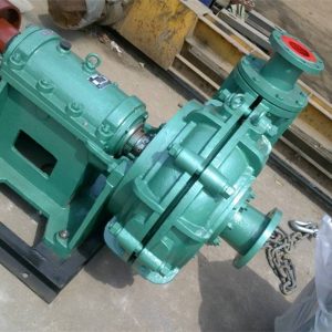
The mud pump mainly transports drilling fluid with high sand content, large specific gravity and high viscosity to the bottom of the well at high pressure during the drilling process.
When working, it is used to cool the drill bit, drive the drilling rig, clean the drilling tool, scour the bottom of the well, fix the well wall, break the rock, and take out the cuttings when returning from the bottom of the well, reduce the friction between the hole wall and the drilling tool, and protect the hole wall from collapsing.
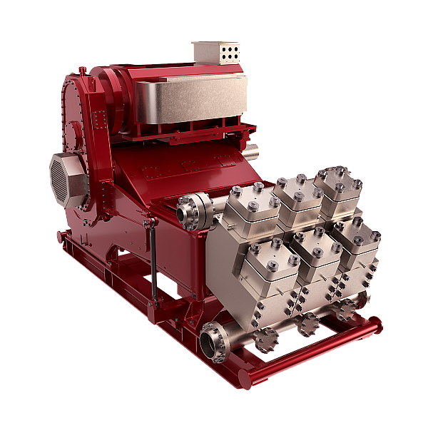
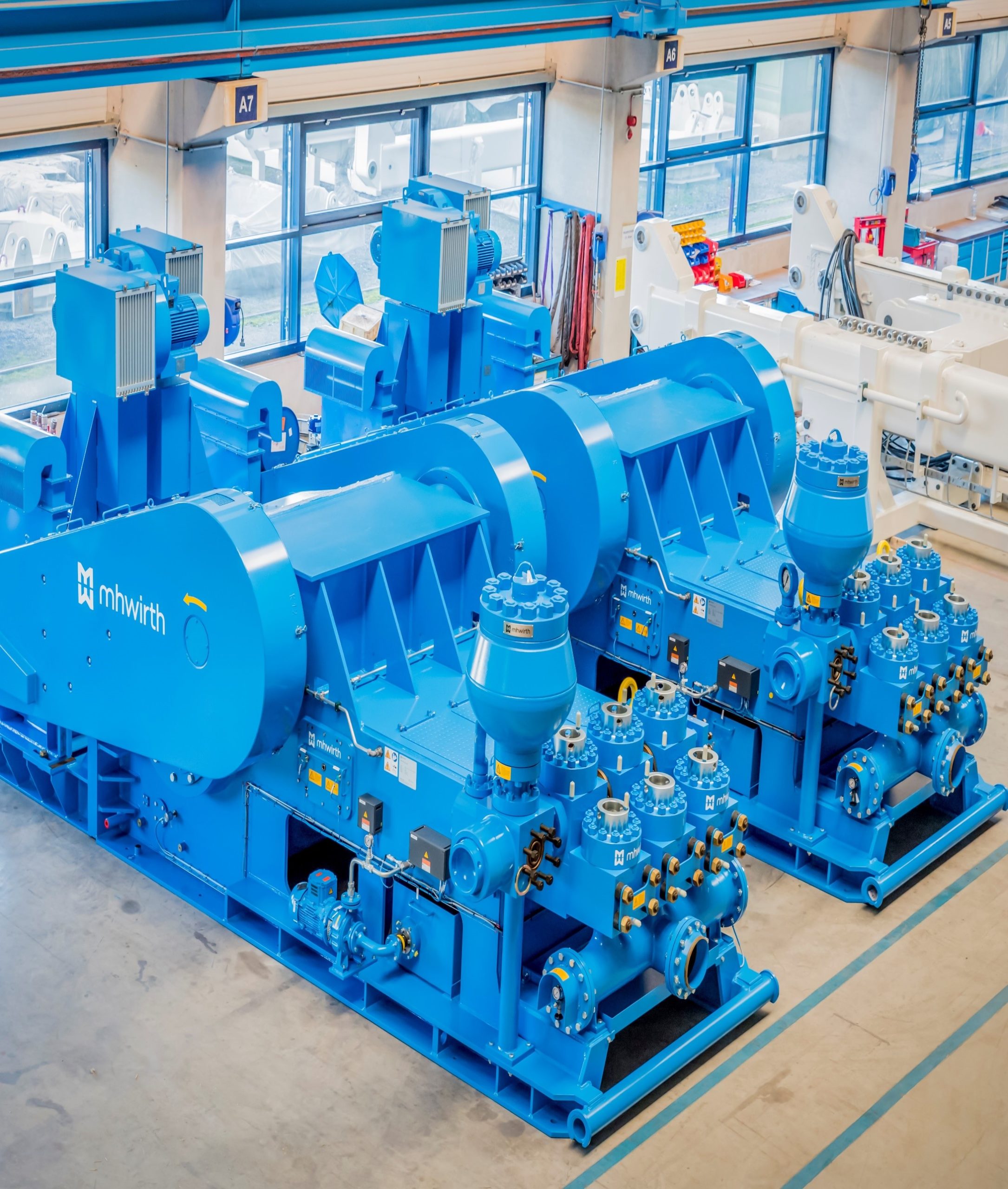
Usually the mud pump can be divided into two parts - the power end and the hydraulic end, and its working process can be divided into two steps of suction and discharge.
The power end of the mud pump is composed of connecting rod, eccentric wheel, cross head, crank, etc., which are used to transmit power, convert movement speed and movement mode, so as to provide suitable power for the hydraulic end.
The hydraulic end is composed of a piston, a pump cylinder, a suction pipe, a suction valve, a discharge pipe, a discharge valve, etc. It can convert the mechanical energy into the internal energy of the liquid, which is used for the transportation of mud.
Under the alternating process of suction and discharge, the purpose of circulating and pressurizing the flushing fluid can be achieved. The medium conveyed by the mud pump usually has high viscosity, high sand content, high pressure and certain corrosiveness. Reasonable daily maintenance and maintenance can prolong the service life of the pump.
The mud pump must be installed on a relatively stable foundation. Before the mud pump is turned on, the lubrication condition, tightening state, fitting clearance, etc. of the various components in the pump should be carefully checked.
The frequent pumping of the mud pump should be avoided as much as possible. When the pump is turned on or reversed, the vaporization of the conveying medium in the pump should be prevented, and the temperature of the medium in the pump should not change greatly during the conveying process. It is due to the uneven heating of the pump body caused by the temperature change, which may lead to deformation and aging of the components in the mud pump.
When the mud pump is transporting medium with higher temperature, the pump should be fully warmed before starting, and the pump can be started when the temperature of the pump body is consistent with the temperature of the medium being transported.
The particle size of the sand transported by the mud pump during the construction process is related to the service life of the vulnerable parts of the mud pump. Air leakage is not allowed in the suction pipeline of the mud pump. The size of the particles passing through the pump should meet the requirements to avoid large particles so as to avoid clogging the mud pump with large particles.
The bearing, pump casing and impeller of the mud pump are the most vulnerable parts. The bearing of the mud pump is bent or has a coaxial deviation with the bearing seat, which will increase the wear of the pump parts and cause the vibration of the pump body.
Most of the damage to the blades of the mud pump is caused by the cavitation of the pump or the inhalation of solid and metal impurities. It is necessary to check and replace the vulnerable parts frequently, or try to use more advanced anti-wear technical measures to increase the service life of wearing parts.
The daily maintenance and maintenance of the china hydraulic mud pump should be carried out by special personnel, and the commonly used and easily damaged mud pump accessories should be equipped for emergency use.
Regularly check and maintain the various parts of the mud pump, solve problems in time, and try to avoid problems and losses during the operation of the mud pump.
How to maintain the mud pump well, it is necessary to ensure that the oil quantity and quality of the lubricating oil are clean, part of the oil bottom needs to be released every month and part of the new oil needs to be replenished, and the oil can be changed every six months.
The bearing assembly is clean and dust-free. Check the temperature change of each part of the bearing to see if there is any abnormal noise. If the temperature is too high, the bearing will be burnt. Always check the working conditions of the mud pump piston and cylinder liner so that the piston can be replaced in time.
Check the use of the valve cover and cylinder head sealing ring, check the wear and erosion of the valve seat, valve body, and valve rubber, and replace it in time. normal.
Check the piston and safety pin of the safety valve, and replace the safety pin of the safety valve installed on the driving shaft in time to ensure that the mud pump can operate safely under drilling conditions.
The mud pump needs a comprehensive disassembly inspection every two years to detect the clearance of the bearing, maintenance and repair or direct replacement, and regular disc pumping of the mud pump in order to prolong the service life of the mud pump.

Prior check to the start of a mud pump for clear water inlet and outlet pipes, buttered front and rear bearings and a filled packing. The China mud pump should be equipped with a high-pressure water pump, which pumps water to the sealing fill with a pressure greater than that of the mud pump. As a protection to the fill, never turn off the water pump while the mud pump is in its working state. Otherwise, the sealing part is of immediate wear.
The service life of the mud pump depends on the clearance between the impeller and the guard plate. An unreasonable clearance is responsible for the vibration and the noise of the pump and the damage of overflowing parts. Therefore, when it comes to the impeller replacement, the clearance shall meet the requirements of the design drawing by adjusting screws on the rear bearing. Take the suction capacity of mud into account for the allowable suction range of the mud pump is determined by water transported.
The Construction Department shall have some professional person responsible for the maintenance and repair of the construction machinery. Regular check and maintenance of the mud pump and other machinery, such as the drilling mud pump parts, are useful for the early detection and a prompt solution.
Pay attention to the size of sediment particles, among which the large ones are prone to wear the vulnerable parts of the China mud pumpsuch as pump shells, bearings, impellers, and so on. Timely maintain the use and replace the damaged. Take advanced anti-wear measures to lengthen the service life of vulnerable parts, which can downturn the cost and up forward the efficiency. Meanwhile, keep backup vulnerable parts in stock in case of unexpected replacement needs.
We keep your mud pumps running in first class condition – providing onsite inspections, repairs and complete overhaul as well as all associated parts.
Periodically we’ll inspect for wear, cracks and damage to critical components such as bearings, bull gear and pinion, conrods and crossheads. We’ll check the condition of your seals and other rubber goods and look for oil contamination. We’ll inspect your frame and ensure your pump is set up as per the manufacturer’s recommended tolerances, providing feedback and detailed reporting.
Where overhaul is required we’ll take care of complete disassembly, cleaning and NDT. Repairs will be made to machined components as necessary. Bearings, seals and other components will be replaced in line with our inspections. Motors will be overhauled, lube systems serviced and pulsation dampeners recertified. We’ll also check your fluid ends are in spec and can repair or replace. Your pump is then fully reassembled and commissioned.
We can do all of this on site or you can ship your crankshaft to a RigQuip location for workshop overhaul. Either way, we’ll work closely with your rig crew and provide first class start up support.

Mud pump refers to a machine that transports mud or water and other flushing fluid into the borehole during drilling. Mud pumps are an important part of drilling equipment, sometimes called sewage pumps and slurry pumps.
(1) Before operating the mud pump, it should be installed on a fixed foundation frame or foundation, and there must be no looseness; after installation, it must be carefully checked whether the joints are tight, the direction of electric rotation is correct, and the clutch is flexible. Reliable, the pipe connection is tight and reliable, the bottom valve is flexible and effective.
(2) In order to ensure the normal operation of the mud pump, the pump should be rotated by hand to make the piston try to make two reciprocating motions. It is determined that there is no obstruction in the machine and the line insulation is good, and the no-load movement can be performed. After the pump body starts to move, can not immediately increase the load, and then gradually increase after the mud pump is running normally.
(3) When the mud pump starts to operate, always pay attention to the sealing condition of each sealing device. If there is a bad seal, it should be adjusted in time. In order to ensure the normal use of the tie rod and the auxiliary rod, it is necessary to apply lubricating oil frequently; It is also necessary to frequently check the sediment content in the mud, and the sand content requirement cannot exceed 10%.
(4) If the mud pump needs to change speed during the operation, it should stop the pump and then shift the gear before starting the operation. It should not be directly changed during the running process. The mud pump with several speeds should be reliable in splash lubrication. During the operation, several speeds will be operated separately, and the time will be no less than 30 seconds.
(5) If the mud pump is abnormal during operation or if the water weight, the pressure is abnormal or the temperature is abnormally high, the pump should be stopped. In normal operation, if there is the no-load condition, stop the pump in time, if the pump is stopped for a long time. It is necessary to open all the water discharge holes, loosen the cylinder head, lift the bottom valve water release rod, and completely drain the mud and sand in the pump body and the pipeline. If it is not used for a long time, it is necessary to thoroughly clean the mud sand of each part. Grease, the lubricant in the crankcase is exhausted, in order to prevent rust, but also take anti-rust and anti-corrosion measures.
Mud pumps are the heart of a drilling operation. TSM designs and manufactures extremely reliable and easy-to-maintain mud pumps, eliminating unnecessary maintenance and downtime.

abstractNote = {The following proposal is based heavily on exponential wear" functions. By simply slowing the main pump down to half rated speed and compensating with the other standby" pump at the same speed, each pump contributes an equal share of required output. This results in remarkable parts life increase, approaching well over twice that of conventional two pump standby" operations (one running and one standby) on typical rig systems. The corresponding reduction in mechanical maintenance is worth noting considering that, presently, the cost of pump parts may reach about $1 million over the life of two drilling rig mud pumps. A single pump operated at reduced speed exhibits enormous parts life increase, but a second pump is needed to make up required output. Even though the number of parts is doubled there is still a relevant economic benefit from increasing parts life.},
Shandong Zhongtan Machinery Co., Ltd. recently launched professional maintenance and consulting services for mud pumps. Whether you are a user of Zhongtan and whether you are using a Zhongtan mud pump, you can dial our after-sales service number: 0635 -6912799, to inquire about the use and maintenance of the mud pump. Through the judgment of our professional after-sales personnel, we will provide you with corresponding maintenance services, including but not limited to video guidance, sending accessories, door-to-door maintenance, etc.
Zhongtan Company has 20 years of professional mud pump manufacturing experience, strong technical accumulation and advanced production technology, as well as experienced engineering and technical personnel, professionally repairing various domestic pumps and imported pumps.
The policy set forth below outlines the personal data that Power Zone Equipment may collect, how Power Zone Equipment uses and safeguards that data, and with whom we may share it. This policy is intended to provide notice to individuals regarding personal data in an effort to be compliant with the data privacy laws and regulations of the jurisdictions in which Power Zone Equipment operates.
Power Zone Equipment is committed to maintaining all reasonable precautions to ensure the privacy and security of personal data gathered by Power Zone Equipment. During your use of our website or through other communications with Power Zone Equipment, personal data may be collected and processed by Power Zone Equipment. In general, Power Zone Equipment collects personal contact information (e.g. name, company, address, telephone number and e-mail address), which you knowingly provide either by registration, requesting quotes, answering questions or otherwise for use in our commercial relationship. At times we may collect additional personal data that you voluntarily provide, including, but not limited to, job title, additional contact information, date of birth, hobbies, areas of interest, and professional affiliations.
Power Zone Equipment’s website is intended to be used by Power Zone Equipment customers, commercial visitors, business associates, and other interested parties for business purposes. Personal data collected by Power Zone Equipment through its website or by other means is used in support of our commercial relationship with you, including, but not limited to, the processing of customer orders, orders from vendors, managing accounts, learning about customers’ needs, responding to inquiries, and providing access to information. Also, in compliance with the laws and regulations of the relevant jurisdiction to support our relationship with you:
we (or a third party on our behalf) may use personal data to contact you about a Power Zone Equipment offer in support of your business needs or to conduct online surveys to understand better our customers’ needs; and
Power Zone Equipment is the commercial operator of its website and uses service providers to assist in hosting or otherwise acting as data processors, to provide software and content for our sites and to provide other services. Power Zone Equipment may disclose personal data supplied by you to these third parties who provide such services under contract to protect your personal data. In addition, where consistent with the laws and regulations of the relevant jurisdiction, Power Zone Equipment may disclose personal data if such disclosure:
For our customers in Switzerland and the European Union (EU), please note that Power Zone Equipment is a US based company. If you use our websites or web portals or, all information, including personal information, may be transferred to Power Zone Equipment (including subcontractors that may be maintaining and/or operating our website) in the United States and elsewhere and may be transferred to third parties that may be located anywhere in the world. Although this may include recipients of information located in countries where there may be a lower level of legal protection for your personal information than in your location country, we will protect your information in accordance with requirements applicable to your information and/or location. Specifically, for data transfers out of the EU, Power Zone Equipment will utilize data transfer agreements containing the Standard Contractual Clauses. By using our websites or web portals, you unambiguously consent to the transfer of your personal information and other information to the United States and elsewhere for the purposes and uses described herein.
When you access Power Zone Equipment’s websites or web portals, we may automatically (i.e., not by registration) collect non-personal data (e.g. type of Internet browser and operating system used, domain name of the website from which you came, number of visits, average time spent on the site, pages viewed). We may use this data and share it with our worldwide affiliates and related service providers to monitor the attractiveness of our websites and improve their performance or content. In this case, processing is performed on an anonymous basis and at Power Zone Equipment’s discretion.
In addition, certain online technical applications or other interactions you have with Power Zone Equipment may require the entry of business and technical data. By providing the requested information, you are consenting to the processing and storage of such information by Power Zone Equipment. Unless Power Zone Equipment is advised that you want this information removed from Power Zone Equipment’s server, such information may be retained by Power Zone Equipment and used for future commercial communications. A request for removal of this information can be made at the contact information provided below. Power Zone Equipment will take all reasonable precautions to assure that no such information will be provided or divulged to other third parties, except, if applicable, those third parties performing site hosting, maintenance, and related site service activities.
Cookies are information stored automatically on a website user’s computer. When a user views Power Zone Equipment’s website(s), Power Zone Equipment may store some data on the user’s computer in the form of a “cookie” to automatically recognize the user upon future visits to Power Zone Equipment’s website(s). Power Zone Equipment will make reasonable efforts to ensure compliance with the laws and regulations of relevant jurisdictions with regard to cookies.
Power Zone Equipment will not knowingly collect personal data from children under the age of 18. Power Zone Equipment’s website(s) is not intended for individuals under 18 years of age
Power Zone Equipment will take reasonable precautions to protect personal data in its possession secure against the risk of loss, misuse, unauthorized access, disclosure, alteration and destruction. Power Zone Equipment periodically reviews its security measures in an effort to ensure the privacy of personal data.
Power Zone Equipment will use personal data only in ways that are compatible with the purposes for which it was collected or subsequently authorized by you. While Power Zone Equipment will take reasonable steps to ensure that personal data is relevant to its intended use, accurate, complete, and current, Power Zone Equipment is also relying upon each individual to assist in providing accurate updates of his or her personal data.
Power Zone Equipment website(s) may contain “links” to websites owned and operated by third parties. By accessing these links, which are provided for your convenience, you will leave our site and will be subject to the privacy practices of the other website. This policy does not apply to any personal information you provide to unrelated third parties.
In general, Power Zone Equipment will only retain personal data for as long as needed for the specific purpose of processing and in accordance with Power Zone Equipment’s records management policy, or as otherwise required by the laws and regulations of a particular jurisdiction. For example, data will be retained during the time period that you are authorized to use Power Zone Equipment website(s), including any Power Zone Equipment tools accessible through our website(s). Upon termination of such authorization, your personal data related to use of Power Zone Equipment website(s) will be removed.
Upon request, Power Zone Equipment will grant individuals reasonable access to personal data that it holds about them. In addition, Power Zone Equipment will take reasonable steps to permit individuals to correct, amend, or delete information that is demonstrated to be inaccurate or incomplete. Power Zone Equipment also relies upon each individual to assist in providing accurate updates of his or her personal data. In order to access, correct, amend, or delete the personal data Power Zone Equipment holds about an individual, the individual should contact the following:
If your personal data is processed in the EU or you are a resident of the EU, the EU General data Protection Regulation grants you certain rights under the law. In particular, the right to access, correct, or delete the personal data Power Zone Equipment holds about you.
To the extent required by applicable law, Power Zone Equipment will grant individuals reasonable access to personal data that Power Zone Equipment holds about them and will take reasonable steps to permit such individuals to correct, amend, or delete information that Power Zone Equipment holds about them. Power Zone Equipment also relies upon each individual to assist in providing accurate updates of his or her personal data. In order to access, correct, amend, or delete the personal data Power Zone Equipment holds about an individual, the individual should contact his or her Power Zone Equipment commercial contact or contact us at the following email address:sales@powerzone.com.
If you have a comment, question, or complaint about how Power Zone Equipment is handling your personal data, we invite you to contact us in order to allow us to resolve the matter. In addition, individuals located in the EU may submit a complaint regarding the processing of their personal data to the EU data protection authorities (DPAs). The following link may assist you in finding the appropriate DPA:http://ec.europa.eu/justice/data-protection/bodies/authorities/index_en.htm.

Maintaining /monitoring the mud pumps and mud pits during operations. Notifying the Driller immediately of any unexplained pit level increases/decreases Verify and record drilling fluid properties at ...
Perform daily inspections and maintenance on electrical equipment. Comply with the permit to work and isolation systems. Carry out periodic maintenance according to the guidelines Maintain, troubleshoot ...
and decisivemanner Otherduties as required by the Rig Manager Minimum Qualifications: Ability to perform essential functions of this position with or without reasonable accommodations. Previous ...
and decisivemanner Otherduties as required by the Rig Manager Minimum Qualifications: Ability to perform essential functions of this position with or without reasonable accommodations. Previous ...
and decisivemanner Otherduties as required by the Rig Manager Minimum Qualifications: Ability to perform essential functions of this position with or without reasonable accommodations. Previous ...
Assist internal and external customers with troubleshooting of Rig Equipment (Top Drive, Catwalk, Wrench, Drawworks, VFDs, Generators, Mud Pumps, BOP) Expeditiously work to troubleshoot and resolve downtime ...
include but are not limited to safely and efficiently performing all tasks within the Rig Operations Areas of the Platform at the direction and under the supervision of the Crane Operator. Tasks may include ...
and special projects as may be directed. Additional functions N/A Qualifications Necessary qualifications, skills and abilities Able to identify and understand functionality of various rig equipment. ...
and special projects as may be directed. Qualifications Necessary qualifications, skills and abilities Able to identify and understand functionality of various rig equipment. Able to identify and understand ...
Our Technical Sales Representative (TSR) is responsible for building on a very high level of product line & operational knowledge and experience to proactively and strategically sell specific tools, technologies ...
Assist higher level technicians, as well as work independently with minimal supervision. Promote a safe and quality environment in which to work Perform preventative maintenance requirements and maintain ...
include but are not limited to: Safely and efficiently performing all tasks on the rig floor and B.O.P. area under the direction and supervision of the Driller. Operating the tongs, slips, and spinners ...
and special projects as may be directed. Qualifications Necessary qualifications, skills and abilities A High School diploma is required. Should have at least 2 years of specific work experience. Must ...
Please note that we are planning to come to the following countries for Recruitment Campaign in the month of May 2023 - Romania - Azerbaijan - Croatia Minimum requirement/ Basic Function Carries out the ...
as required by the Driller, Derrickhand or Rig Manager Minimum Qualifications: Ability to perform essential functions of this position with or without reasonable accommodations Ability to ...
Assists the Driller, Derrickman and/or Motorman in carrying out all routine, non-routine and emergency operational activities around the rig floor areas or any other area of the rig location as designated ...
as required by the Driller, Derrickhand or Rig Manage Minimum Qualifications: Ability to perform essential functions of this position with or without reasonable accommodations Ability to ...
Assists the Crew Pusher and/or TRS Lead in carrying out all routine, non-routine and emergency operational activities around the rig floor areas or any other area of the rig location as designated by ...
ISO 9002 certified distributor of a wide range of pumps & related process equipment including: diaphragm, progressive cavity, Leakproof canned motor centrifugal, Hastelloy C process centrifugal, corrosion resistant gear, epoxy, internal gear, Hydra-cell high pressure diaphragm, centrifugal, Iwaki centrifugal, modular drum and container, centrifugal, side channel & vertical inline, centrifugal & multi-stage centrifugal. Custom manufacturer of fiberglass sump & spill-stop pumps. Services include pump repair, re-building industrial mechanical equipment to factory standards & dynamic balancing. UL certified for rebuilding Class I, Group C & D, Division I, XP equipment. Factory authorized service for most products.

SDS PMS Equipment: Mud Pump Department: Mechanical Manufacturer: Gardner Denver Frequency: Annually Model: PZ-8/9 Issued: PSS Code: GA-327-32 Completed:Item Level Inspect Description
1. [M3] [ ] Insure proper work permits are obtained before performing maintenance on this equipment. 2. [M3] [ ] Insure personnel performing this maintenance is familiar with the equipment and manufacturer"s operation and maintenance manual before beginning. 3. [M2] [ ] Make arrangements with the Rig Superintendent before performing this task and insure that it will not affect the drilling operations. 4. [E2] [ ] Isolate and tag out the electric power to the mud pump. 5. [M3] [ ] Close and tag out the pump suction and discharge valves.
Condition Evaluation Particulars Equipment Description: Manufacturer Model: Serial Number PSS Code & Tag Number: Maximum Input Power Driven By: Rig Name District Date of Condition Evaluation: Cummulative Hours on Pump: Hours/Date of Last Condition Evaluation Person in Charge of Condition Evaluation
SDS PMS Equipment: Mud Pump Department: Mechanical Manufacturer: Gardner Denver Frequency: Annually Model: PZ-8/9 Issued: PSS Code: GA-327-32 Completed:Item Level Inspect Description
1. [M3] [ ] Inspect condition of lube oil. If in good condition take a representitive sample and send for laboratory analysis.
2. [M3] [ ] If lube oil is contaminated, drain and flush the crankcase. Clean out the settling chamber in the forward part of the power end floor. Thoroughly clean the oil troughs and the compartment in top of the crosshead guide. Clean the element in the breather cap and clean the suction screen. Refill using Shell Omala 220.or equivalent oil; 130 US gallons. 3. [M3] [ ] Drain and flush clean the chain drive case. Clean the breather element. Refill using Shell Vitrea 150 or equivalent oil 4. [M3] [ ] Remove the all bearing and crankcase covers for inspection of the following components. Insure nothing drops inside. 1. Check the safety retaining wires on all bolts including the main bearing hold down bolts, eccentric bearing retainer bolts and gear retainer bolts. Replace any broken wires after re- tightening the bolts. Refer to crankshaft assembly section for torque values. 2. Visually inspect all bearings for damage or wear while rotating pump slowly. With a feeler gauge check and record all bearing diametrical clearances. Record the condition and clearances on the Checking Form below. 3. Inspect the ring wear and oil seal condition on the left and right side main bearings. 4. Inspect all main and eccentric bearings for cracked inner & outer bearing races. Inspect the bronze bearing cages for damage or cracks. 5. Make a complete visual inspection of all components checking for looseness, wear or damage. 6. Check the main and pinion gears for condition and wear. Measure and record the backlash. 7. Check each connecting rod retaining bolts for tightness and retaining wires for proper installation. 8. Run lube oil pump and insure all nozzles are free and clear and have a good spray pattern. 5. [M3] [ ] Remove the diaphragm stuffing box and plate. Check the safety retaining wires of the extension rods insuring none broken or missing. Where wire is broken or missing inspect all bolts for crack and thread damage. Retorque to 350 - 370 ft/lbs. Re-install all safety retaining wires. 6. [M3] [ ] Renew lip oil seal and "O" rings, clean and replace plate and stuffing box. Torque bolts to 12 - 18 ft/lbs.
SDS PMS Equipment: Mud Pump Department: Mechanical Manufacturer: Gardner Denver Frequency: Annually Model: PZ-8/9 Issued: PSS Code: GA-327-32 Completed:Item Level Inspect Description
7. [M3] [ ] Remove the ispection covers for the crossheads and carry out the following ispections: 1. Check crosshead pin retainer bolt tightness using torque wrench. Torque value 210 ft/lbs. Insure all locking wire is properly installed 2. Measure the play of the bearing, roller and crosshead pin. Record the readings on the checking form below. 3. Check crosshead clearance, use a feeler gauge between crosshead and upper crosshead guide. Do not operate pump with less than 0.010" clearance. Record the clearances on the Checking Sheet below. They should be .010 - .020. 4. Inspect crosshead and guides for condition and uniform wear. Insure there are no scratches or abnormal wear on the upper or lower slide guides. 5. Check the crosshead slide to frame bolts for tightness. 6. Check the pony rod (extension rod) surface condition for damage or scratches. A deterirated surface will cause premature failures of seals. 7. Check the pony rod to crosshead bolts for correct tighness.
8. [M3] [ ] Check for proper crosshead alignment. Refer to manufacturer"s manual for correct method to use. Record below: Top Front Top Back #1 Cylinder #2 Cylinder #3 Cylinder Note: If the centreline of the extension rod exceeds 0.015" low, re-shimming of guides is necessary
Misalignment can be detected by uneven wear on the pony (extension) rods. Premature liner wear will also be a result. Refer to the mud pump fluid end log book for signs of premature liner wear.
9. [M3] [ ] Check all drive chain and sprockets for wear. New chain - 20 P. = 30" Worn out chain = 30.750" Record the measurements on the Checking Sheet below. 10. [M3] [ ] Inspect and test run the chain oil pump. Overhaul and align as necessary. 11. [M3] [ ] Inspect and test run the gear oil pump. Overhaul and align as necessary. 12. [M3] [ ] Renew the oil pump filter element. 13. [M3] [ ] Inspect and test run the flushing pump. Overhaul, repack and align as necessary.
SDS PMS Equipment: Mud Pump Department: Mechanical Manufacturer: Gardner Denver Frequency: Annually Model: PZ-8/9 Issued: PSS Code: GA-327-32 Completed:Item Level Inspect Description
14. [M3] [ ] Inspect the pony rod end and clamp for wear, damage and cracks. It is essential that a good face to face spigot connection of these rods is maintained. Improper tightening, dirt or debris on the faces when clamped up or the mixing of clamp halves, can lead to fatique cracking of the clamp area. Insure that drilling department is installing the clamps correctly. They must always be torqued evenly with equal gaps between clamp halves is maintained.
15. [M3] [ ] Clean breathers on chain case and gear box. 16. [M3] [ ] Restore power to unit and remove tag. 17. [M3] [ ] Check chain lube oil pressure and record ________ psi. 18. [M3] [ ] Check gear box lube oil pressure and record ________ psi. 19. [M3] [ ] Simulate electric driven gear lube oil pump failure: Record pressure_________ psi. Min 30 psi, max 40 psi. 20. [M3] [ ] Make a complete internal inspection to insure all tools and rags have been removed. Replace all covers and reconnect the pony rod clamp. Make a complete inspection around unit insuring pump condition is ready for operation.
CAUTION: Use extreme caution whenever using RTV for sealing the gaskets faces. Do not use RTV if possible. In many cases pumps have been totally ruined, when too much RTV is applied; the excess gets squeezed into the pump mixing in the oil and eventually plugging oil passages resulting in failures.
Maximum Allowable Bearing Wear The following are figures found to be pactical and acceptable in determining the condition of the bearings. These figures apply provided that the bearings have passed a visual inspection. The highest values are extreme outer limits and in some cases the bearing may begin to spall which will result in damage to other components. Bearing wear and spalling will first be detected in a lube oil analysis.
0.008 - 0.010 Okay to run untill the next annual inspection 0.011 - 0.013 Replace at the next scheduled maintenance. 0.014 - 0.016 Replace at first opportunity. 0.017 and greater Stop Pump and replace immediately.
21. [M3] [ ] Enter details of completion on PMS history card. and file a copy of the completed Condition Evaulation form in the maintenance file.
SDS PMS Equipment: Mud Pump Department: Mechanical Manufacturer: Gardner Denver Frequency: Annually Model: PZ-8/9 Issued: PSS Code: GA-327-32 Completed:Item Level Inspect Description
File: Document1 Last Revised: November 14, 2017 Page 5 of 9 Drilling Services
SDS PMS Equipment: Mud Pump Department: Mechanical Manufacturer: Gardner Denver Frequency: Annually Model: PZ-8/9 Issued: PSS Code: GA-327-32 Completed:Item Level Inspect Description
Guidelines for Replacing a Roller Chain Roller chain is recognized as an exceptionally dependable means for the positive transmission of power. To assure optimum performance and maximum efficiency, it is desirable to anticipate the occasional need for chain replacement, thereby avoiding unexpected interruption or delays in operation. Joint wear, certain overload conditions, metal fatigue, or pitch elongation will limit the useful life of any chain; therefore, the following information will aid in determining when chain replacement is advisable. Effects of Chain Wear During operation, chain pins and bushings slide against each other as the chain engages, wraps, and disengages from its sprockets. Even when the parts are well-lubricated, some metal-to-metal contact does occur, and these parts eventually will wear. This progressive joint wear elongates chain pitch, causing the chain to lengthen and ride higher on the sprocket teeth. The number of teeth in the large sprocket determines the amount of joint wear that can be tolerated before the chain jumps or rides over the ends of the sprocket teeth. When this critical degree of elongation is reached, the chain must be replaced.
Determination of Chain Wear An evaluation of a chain"s useful service life requires an analysis of pitch elongation. By placing a certain number of pitches under tension, elongation can be measured. When elongation equals or exceeds the limits in Table 1, chain should be replaced. The following procedure is suggested: 1. Remove chain from sprockets and lay on smooth, horizontal surface or suspend vertically. To remove slack from a chain measured in a horizontal position, refer to Table2 and apply the load indicated for the size chain involved. If chain must be measured while on sprockets, remove slack on a span of chain and apply sufficient tension to keep chain taut. See Figure below. 2. When chain is properly tensioned, consult Table 1 for the number of pitches which should be measured. This number is determined by chain size and number of teeth in largest sprocket. Pitches should be measured from center to center of pins as shown in Figure above. A steel tape will facilitate accurate measurement. If chain has offset links, do not include them in the measured segment. Select the appropriate column according to number of teeth in largest sprocket and compare published figure with measurement taken. If measurement equals or exceeds figure in Table 1, chain should be replaced.
SDS PMS Equipment: Mud Pump Department: Mechanical Manufacturer: Gardner Denver Frequency: Annually Model: PZ-8/9 Issued: PSS Code: GA-327-32 Completed:Item Level Inspect Description
Chain Measuring Length Number of Teeth in the Largest Sprocket Number ANSI Pitch Number Nominal Length of Chain (inches) When Replacement is Required Inches Of Length Pitches Inches 35 .375 32 12.00 12.38 12.34 12.31 12.28 12.25 12.22 12.19 12.16 40 .500 24 12.00 12.38 12.34 12.31 12.28 12.25 12.22 12.19 12.16 50 .625 20 12.50 12.88 12.59 12.81 12.78 12.75 12.72 12.69 12.66 60 .750 16 12.00 12.38 12.34 12.31 12.28 12.25 12.22 12.19 12.16 80 1.00 24 24.00 24.75 24.69 24.63 24.56 24.50 24.44 24.38 24.31 100 1.250 20 25.00 25.75 25.69 25.63 25.56 25.50 25.44 25.38 25.31 120 1.500 16 24.00 24.75 24.69 24.63 24.56 24.50 24.44 24.38 24.31 140 1.750 14 24.50 25.25 25.19 25.13 25.06 25.00 24.94 24.88 24.81 160 2.000 12 24.00 24.75 24.69 24.63 24.56 24.50 24.44 24.38 24.31 180 2.250 11 24.75 25.50 25.44 25.38 25.31 25.25 25.19 25.13 25.06 200 2.500 10 25.00 25.50 25.44 25.38 25.31 25.25 25.19 25.13 25.06 240 3.000 8 24.00 24.75 24.69 24.63 24.56 24.50 24.44 24.38 24.31
If a chain breaks or fails due to broken pins, sidebars, or rollers, emergency temporary repairs may be required in order to avoid a long shutdown. However, replacement of the entire chain is preferred for the following reasons: 1. If one section of a chain has broken because of fatigue, other sections probably have suffered fatigue damage as well and are subject to early failure. 2. If the chain has been broken by a single high overload, parts other than those at the point of failure are usually bent or severely weakened.
SDS PMS Equipment: Mud Pump Department: Mechanical Manufacturer: Gardner Denver Frequency: Annually Model: PZ-8/9 Issued: PSS Code: GA-327-32 Completed:Item Level Inspect Description
Proper chain tension is obtained by adjusting the sag (catenary) in the unloaded span. For most horizontal and inclined drives, chain should be installed with a depth of sag amounting to approximately 2% of the sprocket centers. See Table 3 for proper sag for various sprocket centers. To measure sag, pull the bottom span of the chain taut, allowing all of the excess chain to accumulate in the upper span. Then, place a straightedge on top of the sprockets and use a scale to measure sag. See figure below. For drives on vertical centers, or those subject to conditions such as shock loads, rotation reversals, or dynamic braking, install chain almost taut. It is essential to inspect such drives regularly for correct chain tension.
Table 3. Chain Sag Based On 2% of Sprocket Centers Sprocket Centers, Sag in Inches Inches 20 .50 30 .63 40 .88 60 1.25 80 1.63 100 2.00 125 2.50
SDS PMS Equipment: Mud Pump Department: Mechanical Manufacturer: Gardner Denver Frequency: Annually Model: PZ-8/9 Issued: PSS Code: GA-327-32 Completed:Item Level Inspect Description

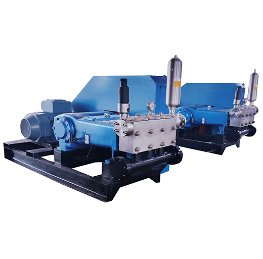
F 1300 mud pump for oil drilling have features of solid and compact structure, small volume, good and reliable performance. It can meet the drilling requirements such as high pressure and big displacements whether in land drilling or off-shore drilling.
F 1300 mud pumps have a longer stroke and can be operated at a lower stroke, thus improved the water supplying performance effectively and extended the lifetime of mud pump fluid end parts greatly.


 8613371530291