
mh wirth mud pump manual free sample

Our precise equipment design and production processes reduce wear and tear, as well as, maintenance downtime and costs. Our precise machining makes shimming obsolete; the pump is ready to use after set-up and runs smoothly throughout the operation. Very low noise and vibrations levels increase the HSSE performance.
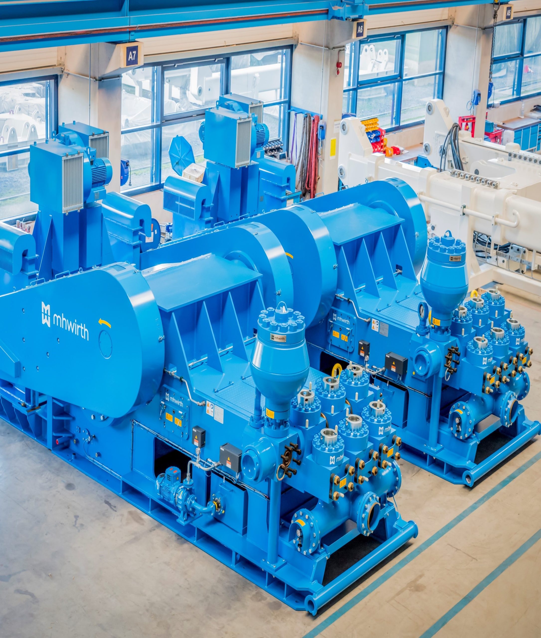
With a large variety of drives, motor and skid configurations, HMH provides a mud pump solution for any project and drilling requirement. We deliver high pressure triplex mud pumps with a maximum discharge pressure between 5 000 and 10 000 psi and power ratings between 1 000 and 2 200 hp.
Our mud pumps reduce service costs and increase operational efficiency. Our unique gear driven drive has an extended lifetime of up to 50 000 hours and is more durable than traditional chain or belt driven drives. Our hydraulic quick release system allows fast and safe replacement of fluid end parts.
The 1600 hp mud pumps are designed to circulate drilling fluid under high pressure (up to 7 500 psi) down the drill string to support any project requirements.
The 2200 hp mud pumps are designed for circulating drilling fluid under high pressure (up to 10 000 psi) down the drill string to support especially deep drilling operations.

MHWirth provides global drilling lifecycle services (DLS) to all drilling equip-ment and systems customers around the world. Uninterrupted installation,commissioning and operation are essential benefits for our customers due tofinancial gains. Besides training, personnel for installation and commission-ing, and providing support throughout the operational phase, the supply ofspare parts is a vital part of our service.
We are a professional provider of OEM (Original Equip- With DLS offices and warehouses situated in local hubs,ment Manufacturer) parts with a vision to be the pre- we are always close to your project. Our experiencedferred partner for the supply of spare parts. We guaran- Service Account Managers are ready and available totee our customers the constant availability of all critical support you in resolving any difficulties that may occurreplacement parts and delivery within 24 hours – and of – if need be within a matter of hours – anywhere in thecourse all our delivered components come with a com- world.prehensive performance guarantee. Mud pump consumables
Fluid ends manufactured both from carbon steel and The valve chambers have been designed to complystainless steel as alternative material have a very posi- with the requirements for valve installation according totive impact on the lifecycle costs for triplex pumps API specification 7K.operating under difficult conditions. The stainless steelmodules have a lifespan that exceeds the general two- Inlet and outlet valve bonnets, and all of the componentyear lifespan associated with carbon steel modules. parts therein, are identical and can be easily inter-Consequently, they are economically viable, but are changed. Valve bonnets incorporate a hydraulically-op-depending on various parameters out of the operating erated bolt-tensioning system, which permits the rapidconditions. and safe removal of internal elements.
1 Only suitable for TPK 800 – 1000 to serial no. 46 | 2 Only suitable for TPK 1300-1600 from serial no. 47 to serial no. 57Mud pump consumables
We offer fluid end parts and consumables suitable for various types of mudpumps for each individual application. The hydraulic quick release systemguarantees low downtimes when replacing fluid end parts, and ensures thehighest possible degree of safety (HSE).
We offer two types of mud pump liners. They are de- gally-cast high-chrome sleeves for a greater hardness.signed to be highly durable for operating pressures of A retaining lip at the rear of the liner helps to maintainup to 7 500 psi. the internal chrome/iron wear sleeve and protects against the high pressures encountered in today’sPremium chrome liners market applications. Production with computer-con-We offer high chrome-plated liners for the triplex mud trolled machining ensures tighter tolerances and con-pumps. All liners have forged-steel external hulls, sistent durability and value. The liner is set to matchwhich provide resistance to hoop stress, and centrifu- the pressure rating of the pump for each liner size.
Premium chrome liners Zirconia liners Mud pump consumables
Zirconia liners The improved wear properties directly results in anZirconia liners are commonly used with MHWirth TPK extended service life for the sleeve, while the improvedseries mud pumps. These liners do not produce ID impact strength leads to a reduction in the significantridges which are common in high-chrome liners. ID costs for the replacement of broken liners in the field.ridges are a cause of piston failure. Zirconia sleeves As a consequence of the finer surface finish, there isare much harder than chrome sleeves and are also less friction with the elastomer-metal pump pistons,more durable, resulting in reduced rig downtimes and which in turn ensures an extended piston life andlower ownership costs. The liners are available in sizes reduced pump-cooling requirements.ranging from 4 ½’’ to 7’’. With a zirconia liner, less maintenance at the pumpRegarding its properties, zirconia has three important is required, due to the extended service life achievedadvantages compared other premium liners: for both pistons and liners, consequently leading to a Better impact strength¡ safer environment. Harder¡ Finer surface¡ Zirconia ceramic liners have been proven to be the most cost-effective liners in use in the industry today. These liners offer the consistent quality needed for reliable pump performance, improved safety, and cost savings.
Premium chrome liners Zirconia liners Mud pump consumables
Our different types of mud pump pistons are suitable Seal designfor various applications. Our pistons are designed to This piston uses a guide belt to help direct the pistondeliver maximum performance under almost all drilling into the liner while reducing the wear on the piston rub-conditions. The pistons have sizes ranging from 4 ½” to ber. With the guide belt, small degrees of misalignment7 ½” and are used with all MHWirth mud pump types. can be compensated for and a proper fit in the liner isThey are fully interchangeable with other API-compatible ensured.pistons. The most common piston types recommendedby us are described below; additional alternatives areavailable upon request. Stingray piston These pistons are designed to resist wear and abrasionStandard black piston with guide belt in service applications involving high pressures and non-These pistons are designed to resist wear and abrasion aqueous mud systems.in medium service applications involving water-basedmud environments. Applications All drilling applications featuring any type of synthetic ¡ Applications and oil-based drilling mud (OBM) All drilling applications featuring water-based drilling¡ Can withstand temperatures of up to 212 ° F (100 ° C) ¡ muds Operating pressure ranges from 1 000 psi to 7 500 psi ¡ Can withstand temperatures of up to 225 ° F (107 ° C)¡ One piston per open hole drilling section ¡ Operating pressure ranges from 1 000 psi to 7 500 psi¡ Stingray compoundBlack compound An improved ‘bull-nose’ lip design and urethane of ¡ The piston rubber is made from specially formulated the highest quality enable the stingray to significantlycompounds which are resistant to the effects of outperform the leading competition.heat, oil and water. A fabric-reinforced backing of Two different urethanes bonded together for superior ¡ the piston rubbers creates a wear-resistant seal. performance. All urethane pistons require adequateThe hub is formed from a high-grade steel to ensure cooling for optimum operation.high tensile strength and a long service life. 30 % more urethane compared to cup lip piston ¡ Bonded to hub for increased strength ¡ Cut-back hub protects liner ¡
Standard black piston Stingray piston Stingray HT extreme piston with guide belt Mud pump consumables
Seal design Stingray HT extreme compound Designed especially for triplex pumps to maximise¡ Superior design and high-temperature urethane of the ¡ performance highest quality enable the stingray HT to significantly Constant seal prevents any fluids being squirted by¡ outperform the leading competition piston Bonded dual hardness with 45 % more urethane com- ¡ Solid lip aids piston alignment in liner¡ pared to other pistons Superior abrasion resistance¡ Special additive to reduce friction between piston and ¡ liner. All urethane pistons require adequate cooling forStingray HT extreme piston optimum operation.These pistons are designed to resist wear and abrasion Enhanced chemical degradation resistance ¡ in service applications involving high temperatures and Premium urethane compounds with higher tensile ¡ non-aqueous mud systems. strength
Applications Seal design All drilling applications featuring any type of synthetic¡ Designed especially for triplex pumps to maximise ¡ & oil-based drilling mud (OBM) performance Can withstand temperatures of up to 300° F (148° C)¡ Constant seal prevents any fluids being squirted by ¡ Operating pressure ranges from 1 000 psi to 7 500 psi¡ piston One piston per open hole drilling section¡ Higher seal area moves piston hub away from liner ¡ Seal allows piston to run more concentrically in liner ¡
MHWirth offers a full range of valves and seats for triplex Cross web (CW) valvespumps. There are two different designs for valves and The cross web valve is made from carburised premiumseats which can be selected according to the specific alloy steel to resist wear, to provide an accurate seal,drilling conditions. and to protect against washout or damage to the pump. The original 3-web design allows a maximum flow areaFull open (FO) valves through the seat while providing a maximum seatingFull open valves enable uniform fluid end loading, lead- area for the valve. The body consists of a one-piece de-ing to a longer fluid end life. Virtually no warpage due to sign that contains the insert to the fullest extent with theheat treatment has been encountered because of very minimum use of the material. A patented polyurethanesmall insert extrusion gaps. The axisymmetric shape insert is equipped with a double angle (55 °) seal contactresults in nearly-uniform seat warpage. Serrations in the surface, which allows cylinder priming to be maintainedvalve insert groove lock insert in place, thereby reducing during pump shutdown.swelling of the insert in all environments. The valves are intended for all drilling operations withThe proven design minimises metal-to-metal bearing pressures of up to 7500 psi and a maximum operatingarea between valve and web seat with larger flows temperature of 300°F (149 ° C) for the cross web valveinvolved, increasing valve and seat lives. HT and 170°F (77 ° C) for the cross web valve. The large bearing area on the valve seat promotes a long serviceThe newly-developed insert compound has a tempera- life.ture rating of 300 °F (149 ° C) for the full open HT and160 ° F (71° C) for the full open valve. All are designed inaccordance with API 7K (styles # 6 and # 8).
Full open (FO) valve Cross web (CW) valve Mud pump consumables
Before any maintenance work is carried out, read the pump safety guidelines thoroughly and ¡ apply whenever applicable. Periodically review the information in the safety section with all persons who operate or work ¡ on the pumps.
WARNING! Wear safety harnesses, and ensure safe access is provided to all mud pump items which ¡ cannot be reached from floor/deck level.
Work on the mud pump may only be performed by physically, mentally and technically ¡ competent, duly authorised and certified personnel. Use the permit to work system (PTWS)! ¡ The work area must be adequately lit to assure sufficient all round vision. ¡ Hydraulic hand pump pressure gauges must be calibrated periodically. ¡ Maintain a good housekeeping regime during any service/repair on the mud pumps. ¡ Spare parts should always meet the technical requirements specified by the manufacturer. ¡ This is ensured when using MHWirth original spare parts. Ensure that adequate and suitable tools and equipment are available to perform all mainte- ¡ nance work. Mud pump consumables
CAUTION! Pump, motors, lubrication oil, pipe work and gearboxes may reach temperatures approach- ¡ ing 60°C during normal operation. Maintenance personnel shall be made aware of this and sufficient cooling off time shall be allowed before commencing work on hot parts.
WARNING! Stop and isolate the mud pump from all sources of hydraulic energy and the electrical power ¡ supply as per the operator’s lock out procedure. The pump must be completely depressurised before attempting any work on the fluid end or ¡ piston and liner assemblies. Bursting bladder of pre-charged suction and discharge dampener may cause serious injury ¡ to personnel and damage to equipment. Jets and leaks from high pressure oil may be fatal. Ensure the system is switched off, ¡ depressurised and locked out before any work is performed on the mud pump.
Use only adaptors and reduction pieces which have been approved by RK Kutting. ¡ The lines must be inspected at regular intervals. ¡ Before each installation, the hoses must be inspected for damage, kinks, wear, corrosion, ¡ cracks and other kinds of damage. It is absolutely essential to replace damaged hoses immediately. ¡ Use only hoses with a known working pressure. ¡ To extend the service life of the hose, use only clean media. ¡ If a malfunction is suspected, immediately shut down the product or machine in which the- ¡ hose is installed andreplace the hose. The maximum permitted operating pressure is determined by the weakest element in the ¡ installation.Mud pump consumables
Picture Description Part no All tools in our standard tool package are supplied in an aluminium box, except the piston assembly tool Fig 10 1 Liner puller 11002584 which is mounted to the pump frame local to the fluid end. 1 Fig 11 1 Valve cover puller 11012412 The size of the aluminium box is: L x W x H 1 200 mm x 800 mm x 500 mm Fig 12 1 High pressure hydraulic pump 10234283
Used for pulling the cylinder liners clear of the Used for removing the valve covers on the discharge fluid end. valve housing and the suction valve housings. Mud pump consumables
Fig 12: hydraulic pump Fig 13: hydraulic tool for suction valve Part no: 10234283 housing Part no: 11002814 The hand pump is used to pressurise the various stud tensioning devices used during regular maintenance Four hydraulic tensioning nuts and one hydraulic and for expelling the valve seat. It is also used to break manifold is used to tension the studs that fasten the taper lock on some bearings. the suction valve housing to the discharge valve housing.
This is used to turn the jacking screw as part of the This is used in conjunction with the socket wrench hydraulic bolt tensioning procedure, used for installation for valve closure drawing (part no: 10234304), and and removal of the discharge and suction valve closures. used in conjunction with driveshaft turning in order The torque bar (part no: 11002706) from the standard to turn the driveshaft by hand during maintenance tools set is used in conjunction with this tool. procedures.Mud pump consumables
The pressure intensifier is used in conjunction with the Fig 23: Piston assembly tool hydraulic pump. It increases the pressure output of the Part no: 11019861 pump threefold to 3 000 bar (43 500 psi). It is used to expel the valve seats in the discharge valve housings The piston assembly tool is used to install and the suction valve housings. and de-install the piston on the piston rod. Mud pump consumables
Fig 24 1 Special wear ring pulling device 11004321 The special tools will reduce human work-load during regular standard maintenance activities and can be ordered upon request.Fig 25 1 Manual valve seat puller ”cross web“ 11023700
Fig 25: manual valve seat Fig 26: manual valve seat puller for “cross web” seats puller for “full open” seats Part no: 11023700 Part no: 11051795Mud pump consumables
Details concerning your spare parts order at a glance We want to make the process of ordering spare parts as simple as possible for you. Simply choose the type and size of your MHWirth mud pump from the table below and order the corresponding spare parts (using the part numbers) at www.myDrilling.com. If you need additional information or have further questions, please contact your local Service Account Manager.
Operating pressure: max. 5 bar Flow rate: 25 l/min Power supply: Compressed air 6 – max. 8,4 bar Weight approximately: 170 kg Mud pump consumables
Mechanical valve seat puller – – Wear ring puller 11004321 11031722 –API style # 6Hydraulic valve seat puller 210325413 – Liner puller 11041842 – Suitable from serial no. 17 upwardsAPI style # 6 3 Only for pumps which are equipped with hydraulic quick release systemMud pump consumables
3 Only for pumps which are equipped with hydraulic quick release system Mud pump consumables
3 Only for pumps which are equipped with hydraulic quick release system | 4 Only for “modification kit”Mud pump consumables
Amplifier for hydraulic puller 10234285 10234285 Liner puller 11002584 – TPK 1600 suitable from serial no. 58 upwards TPK 2000 suitable from serial no. 58 upwards 5 Only for p umps which are equipped with hydraulic quick release system Mud pump consumables
Mechanical valve seat puller 11051795 11023700 Wear ring puller 11004321 11004045 –API style # 8Hydraulic valve seat puller 10234283 3 10234283 3 Liner puller 10234300 – –API style # 8Amplifier for hydraulic puller 10234285 10234285 3 Only for pumps which are equipped with hydraulic quick release systemContact
Lokbatan District,Salyan Highway - 15th km Australia Contact InformationAZ1063 Baku 96 Raubers Road, Northgate spare.parts@mhwirth.comAzerbaijan 4013 Queensland marketing@mhwirth.com+994 12 5650 965 Australia mhwirth.com +61 7 3164 900
Global Operational Support Center Middle East 24/7 technical support for critical Level 20, Platinum Tower issues on operational rigs Jumeirah Lakes Towers +47 3805 7911 Dubai +47 9911 2000 United Arab Emirates 911support@mhwirth.com +971 4 550 6200
mhwirth.com © 2020 MHWirth 51000721.4-0920
MHWirth’s field-proven top drives are designed to perform safe, effective and uninterrupted operations for both conventional and RamRig solutions; on land and offshore installations.
It is equipped with a valve to dial, remote control operated, which reduces the loss and leakage of drilling mud when the reviews coming out or is disconnected after driving over the rig floor.
Reduce costs by streamlining the drill: MHWirth DDM-650HY Top Drive eliminates downtime caused by the difficulty of putting the bushing of the rotary dial. In travel is eliminated and time required for the swivel and kelly back in its holster.
Rotation and continuous circulation during the movement of the drill string, the most important feature in the top drive drilling, and pumping capacity to rotate continuously while-putting reviews or reviews, out of the hole. Only where necessary continuous rotation can be applied to traffic while entering or leaving the hole with the drill string in directional or horizontal wells. Reduce friction between the drill string and the walls of the hole, and in the case of probable landslides packaging effectively remove the effect of rotation and movement.
MHWirth DDM-650HY Top Drive is a more secure and easier to implement, simultaneously, torsion and tension that is required in point operations free and loosened the string.
Connections are screwed and unscrewed at any level of the tower: The driller has a better control of the well to be able to connect and move the string at any height of the tower, rather than relying on a manual valve control and having to dial up and connect and swivel.
![]()
The piston is one of the parts that most easily become worn out and experience failure in mud pumps for well drilling. By imitating the body surface morphology of the dung beetle, this paper proposed a new type (BW-160) of mud pump piston that had a dimpled shape in the regular layout on the piston leather cup surface and carried out a performance test on the self-built test rig. Firstly, the influence of different dimple diameters on the service life of the piston was analyzed. Secondly, the analysis of the influence of the dimple central included angle on the service life of the piston under the same dimple area density was obtained. Thirdly, the wear of the new type of piston under the same wear time was analyzed. The experimental results indicated that the service life of the piston with dimples on the surface was longer than that of L-Standard pistons, and the maximum increase in the value of service life was 92.06%. Finally, the Workbench module of the software ANSYS was used to discuss the wear-resisting mechanism of the new type of piston.
The mud pump is the “heart” of the drilling system [1]. It has been found that about 80% of mud pump failures are caused by piston wear. Wear is the primary cause of mud pump piston failure, and improving the wear-resisting performance of the piston-cylinder friction pair has become the key factor to improve the service life of piston.
Most of the researchers mainly improve the service life of piston through structural design, shape selection, and material usage [1, 2]. However, the structure of mud pump piston has been essentially fixed. The service life of piston is improved by increasing piston parts and changing the structures of the pistons. However, the methods have many disadvantages, for example, complicating the entire structure, making piston installation and change difficult, increasing production and processing costs, and so on. All piston leather cup lips use rubber materials, and the material of the root part of the piston leather cup is nylon or fabric; many factors restrict piston service life by changing piston materials [3]. Improving the component wear resistance through surface texturing has been extensively applied in engineering. Under multiple lubricating conditions, Etsion has studied the wear performance of the laser surface texturing of end face seal and reciprocating automotive components [4–6]. Ren et al. have researched the surface functional structure from the biomimetic perspective for many years and pointed out that a nonsmooth surface structure could improve the wear resistance property of a friction pair [7, 8]. Our group has investigated the service life and wear resistance of the striped mud pump piston, and the optimal structure parameters of the bionic strip piston have improved piston service life by 81.5% [9]. Wu et al. have exploited an internal combustion engine piston skirt with a dimpled surface, and the bionic piston has showed a 90% decrease in the average wear mass loss in contrast with the standard piston [10]. Gao et al. have developed bionic drills using bionic nonsmooth theory. Compared with the ordinary drills, the bionic drills have showed a 44% increase in drilling rate and a 74% improvement in service life [11]. The present researches indicate that microstructures, like superficial dimples and stripes, contribute to constituting dynamic pressure to improve the surface load-carrying capacity and the wear resistance of the friction pair [12–21].
In nature, insects have developed the excellent wear-resistant property in the span of billions of years. For instance, the partial body surface of the dung beetle shows an irregularly dimpled textured surface with the excellent wear-resistant property that is conducive to its living environment [7, 8, 22]. The dung beetle, which is constantly active in the soil, shows a body surface dimple structure that offers superior drag reduction. These dimples effectively reduce the contact area between the body surface and the soil. Moreover, the friction force is reduced. Therefore, the dung beetle with the nonsmooth structure provides the inspiration to design the bionic mud pump piston. This paper proposed a new type of piston with dimpled morphology on its surface and conducted a comparative and experimental study of different surface dimpled shapes, thus opening up a new potential to improve the service life of the mud pump piston.
A closed-loop circulatory system was used in the test rig, which was built according to the national standard with specific test requirements. The test rig consisted of triplex single-acting mud pump, mud tank, in-and-out pipeline, reducer valve, flow meter, pressure gauge, and its principle, as shown in Figure 1. Both the pressure and working stroke of the BW-160 mud pump are smaller than those of the large-scale mud pump, but their operating principles, structures, and working processes are identical. Therefore, the test selected a relatively small BW-160 triplex single-acting mud pump piston as a research object, and the test results and conclusion were applicable to large-scale mud pump pistons. The cylinder diameter, working stroke, reciprocating motion velocity of piston, maximum flow quantity, and working pressure of the BW-160 triplex single-acting mud pump were 70 mm, 70 mm, 130 times/min, 160 L/min, and 0.8–1.2 MPa, respectively.
The mud pump used in the test consisted of water, bentonite (meeting the API standard), and quartz sand with a diameter of 0.3–0.5 mm according to actual working conditions. The specific gravity of the prepared mud was 1.306, and its sediment concentration was 2.13%. Whether mud leakage existed at the venthole in the tail of the cylinder liner of the mud pump was taken as the standard of piston failure. Observation was made every other half an hour during the test process. It was judged that the piston in the cylinder failed when mud leaked continuously; its service life was recorded, and then it was replaced with the new test piston and cylinder liner. The BW-160 mud pump is a triplex single-acting mud pump. The wear test of three pistons could be simultaneously conducted.
The mud pump piston used in the test consisted of a steel core, leather cup, pressing plate, and clamp spring. The leather cup consisted of the lip part of polyurethane rubber and the root part of nylon; the outer diameter on the front end of the piston was 73 mm, and the outer diameter of the piston tail was 70 mm, as shown in Figure 2. We proceeded in two parts during the design of the dimpled layout pattern because the piston leather cup consisted of two parts whose materials were different. The dimples at the lip part of the leather cup adopted an isosceles triangle layout pattern, and the dimples at the root part were arranged at the central part of its axial length, as shown in Figure 3(a). Dimple diameter (D, D′), distance (L), depth (h), and central included angle (α) are shown in Figure 3. The dimples on the piston surface were processed by the CNC machining center. Since then, the residual debris inside the dimples was cleaned.
Table 1 shows that average service lives of L-Standard, L-D1, L-D2, and L-D3 were 54.67 h, 57.17 h, 76.83 h, and 87.83 h, respectively. Therefore, the mud pump pistons with dimples provide longer service life than the L-Standard piston. As the dimple diameter increases, the piston service life was improved, and the largest percentage increase of the service life was 60.65%. The service life of the L-D4 piston was about 81.17 h, which increased by 7.94% compared with that of the L-D2 piston, indicating that the piston with dimples at the leather cup root could improve piston service life.
Figure 4 illustrates the surface wear patterns of pistons with different dimple diameters in the service life test. Figures 4(a) and 4(a′) show wear patterns on the surface of the L-Standard piston. This figure shows that intensive scratches existed in parallel arrangement on the piston leather cup surface, enabling high-pressure mud to move along the scratches from one end of the piston to the other easily, which accelerated the abrasive wear failure with the abrasive particles of the piston. Figures 4(b), 4(b′), 4(c), 4(c′), 4(d), and 4(d′) show the wear patterns of the leather cup surfaces of L-D1, L-D2, and L-D3 pistons, respectively. Figures 4(b), 4(b′), 4(c), 4(c′), 4(d), and 4(d′) show that the scratches on the leather cup surface became shallower and sparser and the surface wear patterns improved more obviously as the dimple diameter increased. If the piston leather cup surface strength was not affected to an extent as the dimple diameter increased, the reduced wear zone near the dimple would become greater and greater, indicating that the existence of dimples changed the lubricating status of the leather cup surface, their influence on nearby dimpled parts was more obvious, and they played active roles in improving the service life of the piston.
Figure 5 displays the wear patterns of the leather cup root parts of the L-D4 and L-D2 test pistons. The wear patterns of the nylon root parts of the L-D4 pistons are fewer than those of the L-D2 pistons, as shown in Figure 5. When the leather cup squeezed out high-pressure mud as driven by the piston steel core, it experienced radial squeezing while experiencing axial wear. Therefore, the area with the most serious wear was the piston leather cup root part, and the friction force at the leather cup root was much greater than that at the other areas. The rapid wear at the root decreased the piston load-carrying capacity and then affected the service life of piston. The dimples at the piston leather cup root could reduce the wear of the piston leather cup root and improve the service life of piston.
Figure 6 shows the surface wear patterns of the L-S1 and L-S2 test pistons. In Figures 6(a) and 6(a′), the scratches on the piston leather cup surface became sparse and shallow in the dimpled area. Figures 6(b) and 6(b′) show that the wear was slight in the area close to the dimples. The farther the scratches were from the dimpled area, the denser and deeper the scratches would be. The L-S1 piston had a small dimple central included angle, which was arranged more closely on the piston surface. The lubricating effects of oil storage in each row of dimples were overlaid very well, which was equivalent to amplifying the effect of each row of dimples in Figure 6(b), making the wear on the whole piston leather cup surface slight, preventing the entry of high-pressure mud into the frictional interface, and lengthening the service life of piston.
During the operation of the mud pump piston, the outside surface of the piston leather cup comes in contact with the inner wall of the cylinder liner and simultaneously moves to push the mud. The lip part of the piston leather cup mainly participated in the piston wear and exerted a sealing effect, while the piston root part mainly exerted centralizing and transitional effects. In the mud discharge stroke, the lip part of the piston experienced a “centripetal effect,” and a gap was generated between the lip part and the cylinder liner. The greater the contact pressure between the lip part and cylinder liner of the piston was, the smaller the gap was, and the entry of high-pressure mud into the contact surface between the piston and cylinder liner was more difficult. The piston root easily experienced squeezing under high pressure, and the smaller the equivalent stress caused by the piston root was, the more difficult the squeezing to occur. Hence, the contact pressure at the lip part of the piston and the equivalent stress at the root were analyzed, and they would provide a theoretical basis for the piston wear-resisting mechanism. The ANSYS Workbench module was used to perform a comparative analysis between the contact pressure at the lip part and the equivalent stress at the root of the three kinds of pistons (i.e., L-Standard piston, L-S1 piston, and L-D1 piston). The service life of the L-S1 piston exhibited the best improvement effect, whereas that of the L-D1 piston demonstrated the worst improvement effect. The piston adopted a 1 mm hexahedral grid, and the grid nodes and elements are as shown in Table 4.
The lubricating oil on the mud pump piston surface could reduce the wear of piston and cylinder liner and improve the service life of pistons with the reciprocating movement. The lubricating oil would eventually run off and lose lubricating effect, which would result in piston wear. The finite element fluid dynamics software CFX was used to establish the fluid domain model of the dimpled and L-Standard pistons and analyze the lubricating state on the piston surface. The piston surface streamlines are shown in Figure 10. This figure shows that the lubricating fluid did not experience truncation or backflow phenomenon when passing the surface of the L-Standard piston. When the lubricating fluid flowed through the surface of the dimpled piston, it presented a noncontinuous process. Its flow velocity at the dimpled structure slowed down obviously because it was blocked by the dimpled structure.
When the piston moved in the cylinder liner, a small quantity of solid particles in mud entered gap of piston and cylinder liner and participated in abrasion. The dimpled structure on the piston surface could store some abrasive particles (as shown in Figure 6(a′)) during the piston wear process to prevent these particles from scratching the piston and cylinder liner and generating gullies, thus avoiding secondary damage to the piston and cylinder liner and improving the piston service life.
This paper presented a dimpled-shape mud pump piston; that is, the piston leather cup surface had a dimpled array morphology in regular arrangement. The experimental results can provide the basic data for design engineering of the mud pump piston with a long service life. The comparative analyses of service life and wear patterns for dimpled mud pump pistons and L-Standard pistons were conducted. The main results and conclusions were summarized as follows:(1)The service life of the mud pump piston with dimpled morphology on the surface improved in comparison with that of the L-Standard piston, and the service life increase percentages were from 4.57% to 92.06%.(2)The piston service life would increase with the dimple diameter under the same dimpled arrangement pattern, and the maximum increase in the value of service life was 60.65%.(3)The service life of the piston with dimples increased by 7.94% in comparison with that with none.(4)Under the same dimpled arrangement patterns and area densities, the tighter and closer the dimples were arranged on the piston surface, the longer the service life of piston was, and the maximum increase in the value of service life was 92.06%.(5)Under the same wear time, the wear of the dimpled piston slightly decreased in comparison with that of the L-Standard piston, and the minimum value of wear mass percentage was 3.83%.(6)The dimpled shape could not only change the stress state of the piston structure, improve piston wear resistance, and reduce root squeezing, but also increase oil storage space, improve lubricating conditions, and enable the accommodation of some abrasive particles. Furthermore, the dimpled shape was the key factor for the service life improvement of the mud pump piston.


 8613371530291