
mission mud pump valves free sample

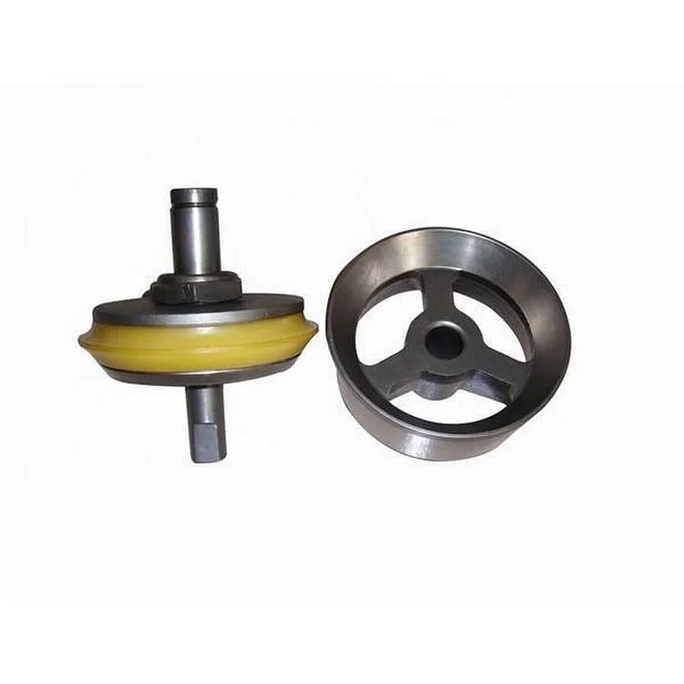
We can supply many kinds of mud pump spare parts to fit your drilling needs, suiting to almost all popular mud pumps in the world.. Such as valve, valve seats, liner, piston, fluid end parts, crankshaft Assembly, Pinionshaft assembly, valve cover, liner cage, liner nut, valve seat puller, extension rod and piston rod, bearing, cylinder etc.
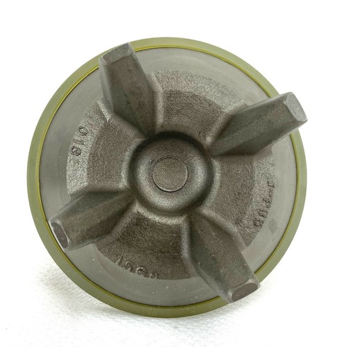
The valve and seat are made of forged alloy steel with deep carburized wear surface. We offer a full range of valves and seats which include full open valve and seat, 3 web / 4 web design valve and seat.
GEA is one of the world"s largest suppliers of systems and components to the food, beverage and pharmaceutical industries. The international technology group, founded in 1881, focuses on machinery and plants, as well as advanced process technology, components, and comprehensive services. With more than 18,000 employees working across five divisions and 62 countries, the group generated revenues of more than EUR 4.7 billion in fiscal year 2021. GEA plants, processes, components and services enhance the efficiency and sustainability of production processes across the globe. They contribute significantly to the reduction of CO2 emissions, plastic usage and food waste. In doing so, GEA makes a key contribution toward a sustainable future, in line with the company’s purpose: "Engineering for a better world".

The hydraulic pump transmits mechanical energy into hydraulic energy. This is done by the movement of fluid which is the transmission medium. There are several types of hydraulic pumps including gear, vane and piston. All of these pumps have different subtypes intended for specific applications such as a bent-axis piston pump or a variable displacement vane pump. All hydraulic pumps work on the same principle, which is to displace fluid volume against a resistant load or pressure.
Hydraulic valves are used in a system to start, stop and direct fluid flow. Hydraulic valves are made up of poppets or spools and can be actuated by means of pneumatic, hydraulic, electrical, manual or mechanical means.
Hydraulic actuators are the end result of Pascal’s law. This is where the hydraulic energy is converted back to mechanical energy. This can be done through use of a hydraulic cylinder which converts hydraulic energy into linear motion and work, or a hydraulic motor which converts hydraulic energy into rotary motion and work. As with hydraulic pumps, hydraulic cylinders and hydraulic motors have several different subtypes, each intended for specific design applications.
There are several components in a hydraulic system that are considered vital components due to cost of repair or criticality of mission, including pumps and valves. Several different configurations for pumps must be treated individually from a lubrication perspective. However, regardless of pump configuration, the selected lubricant should inhibit corrosion, meet viscosity requirements, exhibit thermal stability, and be easily identifiable (in case of a leak).
There are many variations of vane pumps available between manufacturers. They all work on similar design principles. A slotted rotor is coupled to the drive shaft and turns inside of a cam ring that is offset or eccentric to the drive shaft. Vanes are inserted into the rotor slots and follow the inner surface of the cam ring as the rotor turns.
The vanes and the inner surface of the cam rings are always in contact and are subject to high amounts of wear. As the two surfaces wear, the vanes come further out of their slot. Vane pumps deliver a steady flow at a high cost. Vane pumps operate at a normal viscosity range between 14 and 160 cSt at operating temperature. Vane pumps may not be suitable in critical high-pressure hydraulic systems where contamination and fluid quality are difficult to control. The performance of the fluid’s antiwear additive is generally very important with vane pumps.
As with all hydraulic pumps, piston pumps are available in fixed and variable displacement designs. Piston pumps are generally the most versatile and rugged pump type and offer a range of options for any type of system. Piston pumps can operate at pressures beyond 6000 psi, are highly efficient and produce comparatively little noise. Many designs of piston pumps also tend to resist wear better than other pump types. Piston pumps operate at a normal fluid viscosity range of 10 to 160 cSt.
There are two common types of gear pumps, internal and external. Each type has a variety of subtypes, but all of them develop flow by carrying fluid between the teeth of a meshing gear set. While generally less efficient than vane and piston pumps, gear pumps are often more tolerant of fluid contamination.
Internal gear pumps produce pressures up to 3000 to 3500 psi. These types of pumps offer a wide viscosity range up to 2200 cSt, depending on flow rate and are generally quiet. Internal gear pumps also have a high efficiency even at low fluid viscosity.
External gear pumps are common and can handle pressures up to 3000 to 3500 psi. These gear pumps offer an inexpensive, mid-pressure, mid-volume, fixed isplacement delivery to a system. Viscosity ranges for these types of pumps are limited to less than 300 cSt.
Today’s hydraulic fluids serve multiple purposes. The major function of a hydraulic fluid is to provide energy transmission through the system which enables work and motion to be accomplished. Hydraulic fluids are also responsible for lubrication, heat transfer and contamination control. When selecting a lubricant, consider the viscosity, seal compatibility, basestock and the additive package. Three common varieties of hydraulic fluids found on the market today are petroleum-based, water-based and synthetics.
Elevated temperatures cause the water in the fluids to evaporate, which causes the viscosity to rise. Occasionally, distilled water will have to be added to the system to correct the balance of the fluid. Whenever these fluids are used, several system components must be checked for compatibility, including pumps, filters, plumbing, fittings and seal materials.
When selecting lubricants, ensure that the lubricant performs efficiently at the operating parameters of the system pump or motor. It is useful to have a defined procedure to follow through the process. Consider a simple system with a fixed-displacement gear pump that drives a cylinder (Figure 2).
Collect all relevant data for the pump. This includes collecting all the design limitations and optimum operating characteristics from the manufacturer. What you are looking for is the optimum operating viscosity range for the pump in question. Minimum viscosity is 13 cSt, maximum viscosity is 54 cSt, and optimum viscosity is 23 cSt.
Check the actual operating temperature conditions of the pump during normal operation. This step is extremely important because it gives a reference point for comparing different fluids during operation. Pump normally operates at 92ºC.
Using the manufacturer’s data for the pump’s optimum operating viscosity, find the value on the vertical viscosity axis of the chart. Draw a horizontal line across the page until it hits the yellow viscosity vs. temperature line of the lubricant. Now draw a vertical line (green line, Figure 5) to the bottom of the chart from the yellow viscosity vs. temperature line where it is intersected by the horizontal optimum viscosity line. Where this line crosses, the temperature axis is the optimum operating temperature of the pump for this specific lubricant (69ºC).
Repeat Step 8 for maximum continuous and minimum continuous viscosities of the pump (brown lines, Figure 5). The area between the minimum and maximum temperatures is the minimum and maximum allowable operating temperature of the pump for the selected lubricant product.
Find the normal operating temperature of the pump on the chart using the heat gun scan done in Step 2. If the value is within the minimum and maximum temperatures as outlined on the chart, the fluid is suitable for use in the system. If it is not, you must change the fluid to a higher or lower viscosity grade accordingly. As shown in the chart, the normal operating conditions of the pump are out of the suitable range (brown area, Figure 5) for our particular lubricant and will have to be changed.
This rig features a Mission 4-by-5 centrifugal pump. Courtesy of Higgins Rig Co.Returning to the water well industry when I joined Schramm Inc. last year, I knew that expanding my mud pump knowledge was necessary to represent the company"s mud rotary drill line properly. One item new to me was the centrifugal mud pump. What was this pump that a number of drillers were using? I had been trained that a piston pump was the only pump of any ability.
As I traveled and questioned drillers, I found that opinions of the centrifugal pumps varied. "Best pump ever built," "What a piece of junk" and "Can"t drill more than 200 feet with a centrifugal" were typical of varying responses. Because different opinions had confused the issue, I concluded my discussions and restarted my education with a call to a centrifugal pump manufacturer. After that conversation, I went back to the field to continue my investigation.
For the past eight months, I have held many discussions and conducted field visits to understand the centrifugal pump. As a result, my factual investigation has clearly proved that the centrifugal pump has a place in mud rotary drilling. The fact also is clear that many drilling contractors do not understand the correct operational use of the pump. Following are the results of my work in the field.
High up-hole velocity - High pump flow (gpm) moves cuttings fast. This works well with lower viscosity muds - reducing mud expense, mixing time and creating shorter settling times.
Able to run a desander - The centrifugal"s high volume enables a desander to be operated off the pump discharge while drilling without adding a dedicated desander pump.
6. Sticky clays will stall a centrifugal pump"s flow. Be prepared to reduce your bit load in these conditions and increase your rpm if conditions allow. Yes, clays can be drilled with a centrifugal pump.
7. Centrifugal pumps cannot pump muds over 9.5 lbs./gal. Centrifugal pumps work best with a 9.0 lbs./gal. mud weight or less. High flow rate move cuttings, not heavy mud.
The goal of this article has been to increase awareness of the value of the centrifugal pump and its growing use. Although the centrifugal pump is not flawless, once its different operating techniques are understood, drilling programs are being enhanced with the use of this pump.
If you wish to learn more, please talk directly to centrifugal pump users. Feel free to call me at 314-909-8077 for a centrifugal pump user list. These drillers will gladly share their centrifugal pump experiences.

My first days as an MWD field tech I heard horror stories surrounding what is commonly referred to as “pump noise”. I quickly identified the importance of learning to properly identify this “noise”. From the way it was explained to me, this skill might prevent the company you work from losing a job with an exploration company, satisfy your supervisor or even allow you to become regarded as hero within your organization if you’ve proven yourself handy at this skill.
“Pump noise” is a reference to an instability in surface pressure created by the mud pumps on a modern drilling rig, often conflated with any pressure fluctuation at a similar frequency to pulses generated by a mud pulser, but caused by a source external to the mud pulser. This change in pressure is what stands in the way of the decoder properly understanding what the MWD tool is trying to communicate. For the better part of the first year of learning my role I wrongly assumed that all “noise” would be something audible to the human ear, but this is rarely the case.
A mud pulser is a valve that briefly inhibits flow of drilling fluid traveling through the drill string, creating a sharp rise and fall of pressure seen on surface, also known as a “pulse”.
Depending on if the drilling fluid is being circulated in closed or open loop, it will be drawn from a tank or a plastic lined reservoir by a series(or one) mud pumps and channeled into the stand pipe, which runs up the derrick to the Kelly-hose, through the saver sub and down the drill-pipe(drill-string). Through the filter screen past an agitator or exciter, around the MWD tool, through a mud motor and out of the nozzles in the bit. At this point the fluid begins it’s journey back to the drilling rig through the annulus, past the BOP then out of the flow line and either over the shale shakers and/or back in the fluid reservoir.
Developing a firm grasp on these fundamentals were instrumental in my success as a field technician and an effective troubleshooter. As you can tell, there are a lot of components involved in this conduit which a mud pulser telemeters through. The way in which many of these components interact with the drilling fluid can suddenly change in ways that slightly create sharp changes in pressure, often referred to as “noise”. This “noise” creates difficulty for the decoder by suddenly reducing or increasing pressure in a manner that the decoder interprets a pulse. To isolate these issues, you must first acknowledge potential of their existence. I will give few examples of some of these instances below:
Suction screens on intake hoses will occasionally be too large, fail or become unfastened thus allowing large debris in the mud system. Depending on the size of debris and a little bit of luck it can end up in an area that will inhibit flow, circumstantially resulting in a sudden fluctuation of pressure.
This specifically is a term used to refer to the mud motor stator rubber deterioration, tearing into small pieces and passing through the nozzles of the bit. Brief spikes in pressure as chunks of rubber pass through one or more nozzles of the bit can often be wrongly interpreted as pulses.
Sometimes when mud is displaced or a pump suction isn’t completely submerged, tiny air bubbles are introduced into the drilling fluid. Being that air compresses and fluid does not, pulses can be significantly diminished and sometimes non-existent.
As many of you know the downhole mud motor is what enables most drilling rigs to steer a well to a targeted location. The motor generates bit RPM by converting fluid velocity to rotor/bit RPM, otherwise known as hydraulic horsepower. Anything downhole that interacts with the bit will inevitably affect surface pressure. One of the most common is bit weight. As bit weight is increased, so does surface pressure. It’s important to note that consistent weight tends to be helpful to the decoder by increasing the amplitude of pulses, but inconsistent bit weight, depending on frequency of change, can negatively affect decoding. Bit bounce, bit bite and inconsistent weight transfer can all cause pressure oscillation resulting in poor decoding. Improper bit speed or bit type relative to a given formation are other examples of possible culprits as well.
Over time mud pump components wear to the point failure. Pump pistons(swabs), liners, valves and valve seats are all necessary components for generating stable pressure. These are the moving parts on the fluid side of the pump and the most frequent point of failure. Another possible culprit but less common is an inadequately charged pulsation dampener. Deteriorating rubber hoses anywhere in the fluid path, from the mud pump to the saver sub, such as a kelly-hose, can cause an occasional pressure oscillation.
If I could change one thing about today’s directional drilling industry, it would be eliminating the term “pump noise”. The misleading term alone has caused confusion for countless people working on a drilling rig. On the other hand, I’m happy to have learned these lessons the hard way because they seem engrained into my memory. As technology improves, so does the opportunities for MWD technology companies to provide useful solutions. Solutions to aid MWD service providers to properly isolate or overcome the challenges that lead to decoding issues. As an industry we have come a lot further from when I had started, but there is much left to be desired. I’m happy I can use my experiences by contributing to an organization capable of acknowledging and overcoming these obstacles through the development of new technology.


 8613371530291