
mud pump 10 hp free sample
Voltage:___V, Frequency:___hz2, What material pump can you supply?A05, Natural rubber, ceramics, polyurethane etc.3, Can you supply special or OEM parts?Yes, please send me the detailed drawing or parts code to check.4, Do you only supply pumps? Could you supply driven equipment?Yes, sure ,the pumps could be coupled with motor and diesel engine, below brands for your reference:

They are generally run on diesel, gasoline, and electricity. 15 Hp mud pumps work more efficiently in smaller formations like 15 hp mud pumps, but the 15 Hp mud pumps have a traction in the form of a pump, where the traction mud pump is lessertive.
There are many varieties of mud pumps on the platform, such as the 15 Hp boat pump, and 15 Hp mud pump in terms of their usage, they are also called 15 Hp boat pump, and 15 Hp electric pump for example. 15 Hp mud pump is also called the 15 Hp boat pump, and the Hp mud pump in the form of a 15 hp gas pump, while 15 Hp mud pumps are generally divided in two types: 15 hp boat pump, 15 hp electric pump, and 15 hp mud pump for among purposes.
Both Hp mud pumps and hp mud pumps have a tons, on the other hand, the piston pump is a rocket- push type, allowing the pressure to be pushed through the suction pipe.
There are many varieties of water pumps for 15 hours, depending on the size and usage of the pump. 15 hp mud pumps are 15 in 30, and the hp water pumps can 15 up to 15 hours, depending on the size and the design of the pumps.

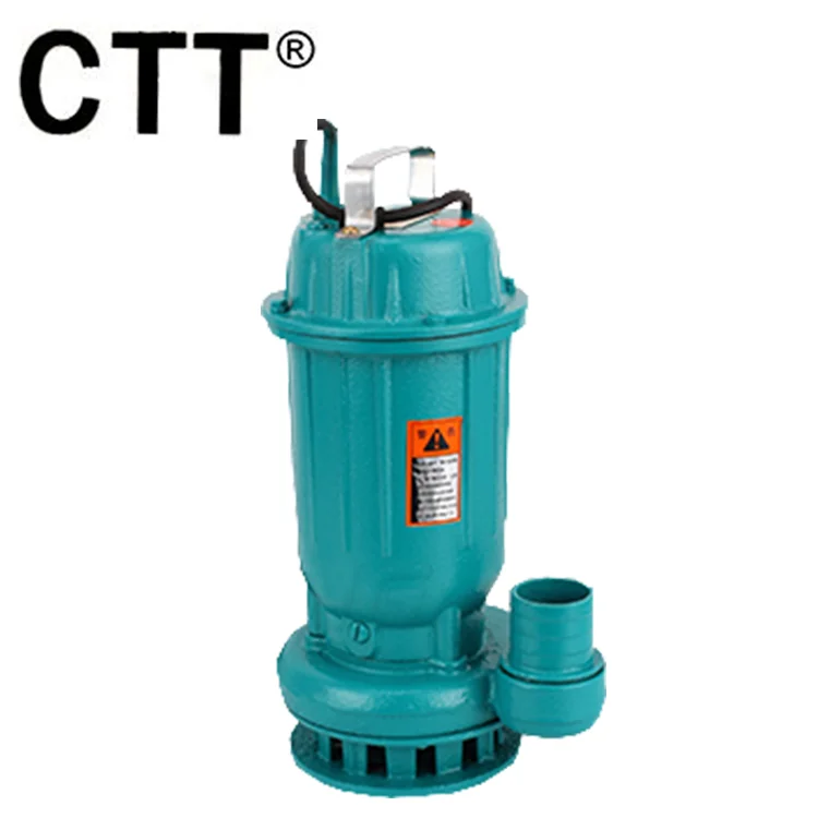
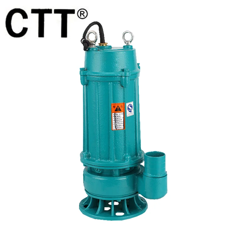
Pump body thick. The pump body is made of high quality pig iron, durable and equipped with a thickened base. Thickened impeller, wear-resistant and dry rotating.
(Place the vertical mud pump upright or tilted in the liquid. Make sure the pump case is completely submerged in water. In addition, the motor part can not be immersed in water.)
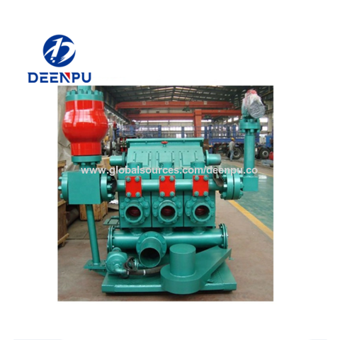
There are two main parts to a mud pump: the fluid end and the power end. The fluid end is where the actual pumping takes place. The components of the fluid end consist of valves, pistons (or plungers), and liners. Since the fluid end is in constant contact with the material being pumped, most modern designs allow for quick replacement of worn components as needed. This dramatically extends the life of a unit without having to completely replace the pump. The power end of a mud pump is responsible for taking the input power, typically through a driveshaft, and converting it into the reciprocating motion needed for the pistons. In most mud pump applications, the power end uses a crosshead crankshaft for this conversion.
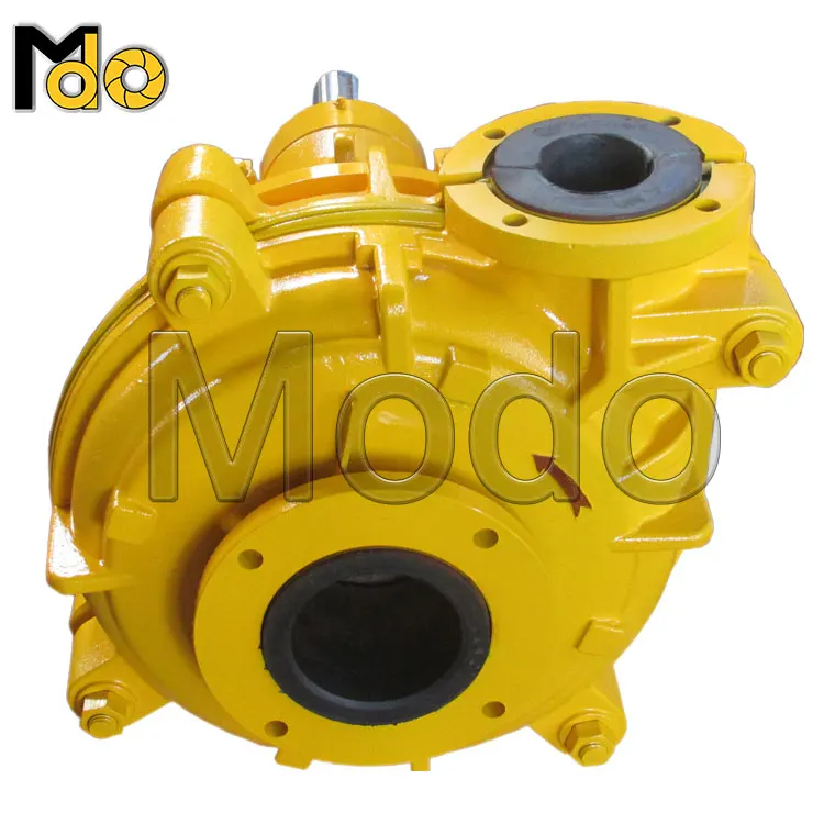
The DAE Pumps Submersible Slurry Pumps are designed for an extensive range of applications. With their robust designs, submersible slurry pumps move slurry, sand, and other material with ease. Heavy-duty submersible slurry pumps from DAE Pumps are capable of pumping solids up to2112 GPM with as much as 102 HP. DAE Pumps submersible slurry pumps are available in a wide range of models in 3-inch, 4-inch, 6-inch, and 8-inch sizes.
Our non-clogging submersible slurry pumps are the toughest in the industry and have the largest apertures to facilitate the handling of slurry with the most challenging solids. The high-efficiency high chrome agitator lifts up to 2.5-inch settled solids. The robust design uses heavy-duty bearings to withstand shocks and overloads and a double silicon carbide mechanical seal for duty application.
DAE Pumps robust submersible slurry pumps are made to perform. The unique sealing system and modular design make them the most flexible pumps on the market. Easy to use and maintain, these pumps provide the optimum maintenance solution and can be easily fitted at the job site. These heavy-duty submersible slurry pumps offer a motor protection system with a built-in starter and optional automatic level control. The hardened high-chrome impellers and adjustable wear-resistant rubber diffuser feature ensure durability in the toughest environments.
At DAE Pumps, we have a complete range of high-quality submersible slurry pumps made for dewatering and dredging the most abrasive media, like sand, with high solid content in quarries and mining operations. The user-friendly design and easy-to-use submersible sand and slurry pumps are why they are the preferred choice for submersible pumps.
Submersible slurry pumps and submersible sand pumps offer the highest in quality and strength over other submersible pumps. They are capable of moving large amounts of sand and slurry with ease and without clogging. DAE Pumps submersible sand and slurry pumps withstand the abrasive material that passes through them on a consistent basis and provide the power to move the material. The following is to help understand pump specifications for selecting the right submersible slurry pump or sand pump for you. A DAE Pumps representative is also available.
The size of the submersible pump is important when connecting the discharge end. The hose or pipe that connects to the pump should match the discharge or the pump. If fitting an adjustment to the end of the submersible slurry pump, the fitting can only work when goes downward in size, not upward. Typically, the pump size limits the gallons per minute a submersible slurry pump is capable of pumping. The larger the pump size, the more allowable volume, and solids sizes.
The power of the electrical submersible slurry pump is determined by the motor size in horsepower. The more horsepower, the more material it can move (volume), and the higher the head of which it can pump. When moving sand and slurry, it is important to take horsepower into consideration. As sand and slurries can be heavy, this causes friction that slows down the movement of the material. If there is too much friction and the submersible sand pump is not powerful enough to push the sand or slurry, the material will start to settle in the hose or piping, and not deliver to the final destination.
When selecting a submersible slurry or sand pump be sure to understand the volume of the material you are looking to move. Submersible pump specifications are typically based on pumping water. When pumping sand, slurry, and other solids, DAE Pumps industrial slurry pumps move between 15% to 30% solids. Therefore, the remaining 70% to 85% is water. While a 100 GPM sand pump can process about 15% material, thus 15 GPM of sand, a 100 GPM slurry pump can process about 30% material, thus 30 GPM of slurry. This all varies depending on how aggressive the operator is with the pump. Ensuring the correct power of a sand pump is essential for delivering sand the distance needed because sand is heavy and settles. Not enough power will leave sand in the hose and backup. Knowing the liquid viscosity is important for ensuring proper pumping. Ask DAE Pumps for assistance with a viscosity test to ensure accurate pump selection.
In addition to the amount of material you pump, you want to make sure there is a consistent inflow of water or fluid replacing liquid and material that is being pumped out for the proper operation. Lack of fluid is never good for submersible pumps.
Here are a couple of equations and examples to help figure out how much material a submersible slurry pump can move and approximately how long it will take to move your material.
The head is the height at which the pump can raise water. The weight of a gallon of water at room temperature is 8.33 lbs. If all that is being pumped is room temperature water, the height a submersible slurry pump could pump that water is the max head stated on the pump specifications. However, submersible slurry pumps and submersible sand pumps are pumping more than just room-temperature water. They are pumping sand, silt, rocks, mud, debris, and other types of slurries. These slurries have a different weight that is more than the weight of water. Thus, the head of a pump that is pumping slurries and sand is going to be less than the stated head on a pump.
The size of solids is that can pass through a submersible slurry pump are typically determined by the allowable area between the pump’s impeller and the volute. Submersible pumps are designed with more or less separation for the type of material they are intended to handle. Those with more separation are submersible slurry pumps because they can process larger materials. The submersible pump with less separation is a drainage pump that does not move many solids.
Your dewatering needs are our top priority. Our electrical submersible pumps support all your dewatering application needs for drainage, slurry, and sludge. Visit our dewatering applications section to learn more about various types of dewatering needs.
The non-clogging Miramar Submersible Slurry Pumps are the toughest and have the largest apertures to facilitate the handling of slurry with the most challenging solids. The high-efficiency high chrome agitator lifts settled solids up to 2.5-inches. The robust design uses heavy-duty bearings to withstand shocks and overloads and a double silicon carbide mechanical seal for duty application. The Miramar Slurry Pumps offer 3-inch, 4-inch, and 6-inch models, with the ability to move up to 2112 GPM.
DAE Pumps Miramar L430 Submersible Slurry Pumps are built to move abrasive materials with solids up to 0.8-inches. With a 3-inch discharge, these slurry pumps process material at 247 GPM up to 47-feet via a 5 HP motor. This 60Hz pump is available in 460V.
The low-cost DAE Pumps Tampa 337 provides ideal suction and movement of solids up to 1-inch through a 3-inch discharge. The ergonomic Tampa 337 submersible slurry pumps transfer solids and liquids at a flow rate of up to 343 GPM and with 5 HP. Read More…
DAE Pumps Tampa 355 provides reliable suction and movement of solids up to 1-inch through a 3-inch discharge. The ergonomic Tampa 355 submersible slurry pumps transfer solids and liquids at a flow rate of up to 449 GPM and with 5 HP. Read More…
The durable and efficient DAE Pumps Tampa 437 provides improved suction and movement of solids up to 1-inch through a 4-inch discharge. The ergonomic Tampa 437 submersible slurry pumps transfer solids and liquids at a flow rate of up to 476 GPM and with 5 HP. Read More…
The durable and efficient DAE Pumps Tampa 437 provides improved suction and movement of solids up to 1-inch through a 4-inch discharge. The ergonomic Tampa 437 submersible slurry pumps transfer solids and liquids at a flow rate of up to 476 GPM and with 5 HP. Read More…
3The Lansing 340 submersible slurry pump is solid and easy to move slurry, water, or any other material. DAE Pumps’ heavy-duty, submersible slurry pumps can handle up to 2112 GPM solids. They also have a maximum power output of 102 horsepower. DAE Pumps Submersible Drainage Pumps are available in many sizes, including3-inch,4-inch,6-inch, and8-inch.
The Lansing 340 submersible slurry pump has a 4kW or 5.5HP, and it is non-clogging and can handle the most challenging solids. The high-efficiency, high chrome agitator, is capable of lifting 2.5-inch solids. For duty use, the sturdy design incorporates heavy-duty bearings for shocks and overloads.
The rugged DAE Pumps Miramar L540 Submersible Slurry Pumps process abrasive materials with solids up to 1-inch. These durable slurry pumps with 4-inch discharge move material at 308 GPM up to 57-feet via a 7 HP motor. This 60Hz pump is available in 460V.
DAE Pumps Tampa 455 provides greater suction and movement of solids up to 1-inch through a 4-inch discharge. The ergonomic Tampa 455 submersible slurry pumps transfer solids and liquids at a flow rate of up to 594 GPM and with 7.5 HP. Read More…
4The Lansing 460 submersible slurry pump is solid and easy to move slurry, water, or any other material. DAE Pumps’ heavy-duty, submersible slurry pumps can handle up to 2112 GPM solids. They also have a maximum power output of 102 horsepower. DAE Pumps Submersible Drainage Pumps are available in many sizes, including3-inch,4-inch,6-inch, and8-inch.
The Lansing 60 submersible slurry pump has a 6kW or 8HP, and it is non-clogging and can handle the most challenging solids. The high-efficiency, high chrome agitator, is capable of lifting 2.5-inch solids. For duty use, the sturdy design incorporates heavy-duty bearings for shocks and overloads.
The reliable DAE Pumps Tampa 475 provides increased suction and movement of solids up to 1-inch through a 4-inch discharge. The ergonomic Tampa 475 submersible slurry pumps transfer solids and liquids at a flow rate of up to 655 GPM and with 10 HP. Read More…
Offering the same high-quality, the DAE Pumps Miramar L640 Submersible Slurry Pumps move abrasive materials with solids up to 1-inch. With a 4-inch discharge, these heavy-duty slurry pumps process material at 440 GPM up to 75-feet via a 12 HP motor. This 60Hz pump is available in 460V.
The heavy-duty DAE Pumps Miramar L740 Submersible Slurry Pumps transfer abrasive materials with solids up to 1-inch. With a 4-inch discharge, the Miramar L740 slurry pumps move material at 616 GPM up to 85-feet via a 15 HP motor. This 60Hz pump is available in 460V.
The efficient DAE Pumps Tampa 4110 provides enhanced suction and movement of solids up to 1-inch through a 4-inch discharge. The ergonomic Tampa 4110 submersible slurry pumps transfer solids and liquids at a flow rate of up to 819 GPM and with 15 HP. Read More…
DAE Pumps Miramar L840 Submersible Slurry Pumps move abrasive materials with solids up to 1-inch. With a 4-inch discharge, these reliable slurry pumps process material at 660 GPM up to 98-feet via a 20 HP motor. This 60Hz pump is available in 460V.
DAE Pumps Galveston 3304 pumps with a combined strainer with a partially open stand and agitator allows for ideal suction and movement of solids up to 1.5-inches with a 4-inch discharge. The Galveston 3304 submersible slurry pumps transfer solids and liquids at a flow rate of up to 792 GPM and with 30 HP. Read More…
The high power 4-inch DAE Pumps Miramar L940 Submersible Slurry Pumps move abrasive materials with solids up to 1.5-inches. These 4-inch discharge submersible slurry pumps move liquids and solids at 880 GPM up to 171-feet via a 50 HP motor. This 60Hz pump is available in 460V.
The DAE Pumps Tampa 6110 provides high suction and movement of solids up to 1.4-inches through a 6-inch discharge. The ergonomic Tampa 6110 submersible slurry pumps transfer solids and liquids at a flow rate of up to 977 GPM and with 15 HP. Read More…
The Lansing 690 submersible slurry pump is solid and easy to move slurry, water, or any other material. DAE Pumps’ heavy-duty, submersible slurry pumps can handle up to 2112 GPM solids. They also have a maximum power output of 102 horsepower. DAE Pumps Submersible Drainage Pumps are available in many sizes, including3-inch,4-inch,6-inch, and8-inch.
The Lansing 690 submersible slurry pump has a 9kW or 12HP, and it is non-clogging and can handle the most challenging solids. The high-efficiency, high chrome agitator, is capable of lifting 2.5-inch solids. For duty use, the sturdy design incorporates heavy-duty bearings for shocks and overloads.
DAE Pumps Tampa 6150 provides enhanced suction and movement of solids up to 1.4-inches through a 6-inch discharge. The ergonomic Tampa 6150 submersible slurry pumps transfer solids and liquids at a flow rate of up to 1136 GPM and with 20 HP. Read More…
The highly efficient DAE Pumps Tampa 6150-L provides even greater suction and movement of solids up to 1.4-inches through a 6-inch discharge. The ergonomic Tampa 6150-L submersible slurry pumps transfer solids and liquids at a flow rate of up to 1453 GPM and with 20 HP. Read More…
DAE Pumps Tampa 6220 provides ideal suction and movement of solids up to 1.2-inches through a 6-inch discharge. The ergonomic Tampa 6220 submersible slurry pumps transfer solids and liquids at a flow rate of up to 1268 GPM and with 30 HP. Read More…
DAE Pumps Galveston 3306 pumps with a combined strainer with a partially open stand and agitator allows for ideal suction and movement of solids up to 2.5-inches with a 6-inch discharge. The Galveston 3306 submersible slurry pumps transfer solids and liquids at a flow rate of up to 1848 GPM and with 30 HP. Read More…
DAE Pumps Galveston 3506 pumps with a combined strainer with a partially open stand and agitator allows for ideal suction and movement of solids up to 1.5-inches with a 6-inch discharge. The Galveston 3506 submersible slurry pumps transfer solids and liquids at a flow rate of up to 2112 GPM and with 50 HP. Read More…
DAE Pumps Galveston 3506-H pumps with a combined strainer with a partially open stand and agitator allows for ideal suction and movement of solids up to 1.5-inches with a 6-inch discharge. The Galveston 3506-H submersible slurry pumps transfer solids and liquids at a flow rate of up to 1848 GPM and with 50 HP. Read More…
DAE Pumps Miramar L1060 Submersible Slurry Pumps are built to move abrasive materials with solids up to 2.5-inches. With a 6-inch discharge, these slurry pumps process material at 1320 GPM up to 108-feet via a 60 HP motor. This 60Hz pump is available in 460V.
The Miramar L1060 is made of aluminum alloy for high corrosion resistance and the high-chrome (55HRC) impellers provide great wear resistance. The wide base is designed for stability while standing in thick material.
DAE Pumps Galveston 3756 pumps with a combined strainer with a partially open stand and agitator allows for ideal suction and movement of solids up to 1.5-inches with a 6-inch discharge. The Galveston 3756 submersible slurry pumps transfer solids and liquids at a flow rate of up to 2112 GPM and with 75 HP. Read More…
DAE Pumps Miramar L1160 Submersible Slurry Pumps offer the ultimate performance in slurry pumping. This top-of-the-line pump easily handles the most abrasive materials with solids up to 2.5-inches. This heavy-duty slurry pump with a 6-inch discharge transfers material at 2112 GPM up to 174-feet via a 101 HP motor. This 60Hz pump is available in 460V.
The Lansing 8150 submersible slurry pump is solid and easy to move slurry, water, or any other material. DAE Pumps’ heavy-duty, submersible slurry pumps can handle up to 2112 GPM solids. They also have a maximum power output of 102 horsepower. DAE Pumps Submersible Drainage Pumps are available in many sizes, including3-inch,4-inch,6-inch, and8-inch.
The Lansing 8150 submersible slurry pump has a 15kW or 20HP, and it is non-clogging and can handle the most challenging solids. The high-efficiency, high chrome agitator, is capable of lifting 2.5-inch solids. For duty use, the sturdy design incorporates heavy-duty bearings for shocks and overloads.
The reliable DAE Pumps Tampa 8220 provides the highest suction and movement of solids up to 1.4-inches through an 8-inch discharge. The ergonomic Tampa 8220 submersible slurry pumps transfer solids and liquids at a flow rate of up to 1664 GPM and with 30 HP. Read More…
DAE Pumps Galveston 3508 pumps with a combined strainer with a partially open stand and agitator allows for ideal suction and movement of solids up to 2.5-inches with an 8-inch discharge. The Galveston 3508 submersible slurry pumps transfer solids and liquids at a flow rate of up to 2112 GPM and with 50 HP. Read More…
DAE Pumps Galveston 3758 pumps with a combined strainer with a partially open stand and agitator allows for ideal suction and movement of solids up to 2.5-inches with an 8-inch discharge. The Galveston 3758 submersible slurry pumps transfer solids and liquids at a flow rate of up to 2112 GPM and with 75 HP. Read More…
The Lansing 8220 submersible slurry pump is solid and easy to move slurry, water, or any other material. DAE Pumps’ heavy-duty, submersible slurry pumps can handle up to 2112 GPM solids. They also have a maximum power output of 102 horsepower. DAE Pumps Submersible Drainage Pumps are available in many sizes, including3-inch,4-inch,6-inch, and8-inch.
The Lansing 8220 submersible slurry pump has a 22kW or 30HP, and it is non-clogging and can handle the most challenging solids. The high-efficiency, high chrome agitator, is capable of lifting 2.5-inch solids. For duty use, the sturdy design incorporates heavy-duty bearings for shocks and overloads.
DAE Pumps Miramar Submersible Slurry Pumps are economical equivalent pumps to Atlas Copco dewatering slurry pumps. The Miramar pumps offer the same high-quality material and performance as Atlas Copco WEDA series. Contact us today to find out more about how DAE Pumps can help you with all your dewatering and material moving needs.

Triplex mud pumps pump drilling mud during well operations. An example of a typical triplex mud pump 10 shown in FIG. 1A has a power assembly 12, a crosshead assembly 14, and a fluid assembly 16. Electric motors (not shown) connect to a pinion shaft 30 that drives the power assembly 12. The crosshead assembly 14 converts the rotational movement of the power assembly 12 into reciprocating movement to actuate internal pistons or plungers of the fluid assembly 16. Being triplex, the pump"s fluid assembly 16 has three internal pistons to pump the mud.
As shown in FIG. 1B, the pump"s power assembly 14 has a crankshaft 20 supported at its ends by double roller bearings 22. Positioned along its intermediate extent, the crankshaft 20 has three eccentric sheaves 24-1 . . . 24-3, and three connecting rods 40 mount onto these sheaves 24 with cylindrical roller bearings 26. These connecting rods 40 connect by extension rods (not shown) and the crosshead assembly (14) to the pistons of the pump"s fluid assembly 16.
In addition to the sheaves, the crankshaft 20 also has a bull gear 28 positioned between the second and third sheaves 24-2 and 24-3. The bull gear 28 interfaces with the pinion shaft (30) and drives the crankshaft 20"s rotation. As shown particularly in FIG. 1C, the pinion shaft 30 also mounts in the power assembly 14 with roller bearings 32 supporting its ends. When electric motors couple to the pinion shaft"s ends 34 and rotate the pinion shaft 30, a pinion gear 38 interfacing with the crankshaft"s bull gear 28 drives the crankshaft (20), thereby operating the pistons of the pump"s fluid assembly 16.
When used to pump mud, the triplex mud pump 10 produces flow that varies by approximately 23%. For example, the pump 10 produces a maximum flow level of about 106% during certain crankshaft angles and produces a minimum flow level of 83% during other crankshaft angles, resulting in a total flow variation of 23% as the pump"s pistons are moved in differing exhaust strokes during the crankshaft"s rotation. Because the total flow varies, the pump 10 tends to produce undesirable pressure changes or “noise” in the pumped mud. In turn, this noise interferes with downhole telemetry and other techniques used during measurement-while-drilling (MWD) and logging-while-drilling (LWD) operations.
In contrast to mud pumps, well-service pumps (WSP) are also used during well operations. A well service pump is used to pump fluid at higher pressures than those used to pump mud. Therefore, the well service pumps are typically used to pump high pressure fluid into a well during frac operations or the like. An example of a well-service pump 50 is shown in FIG. 2. Here, the well service pump 50 is a quintuplex well service pump, although triplex well service pumps are also used. The pump 50 has a power assembly 52, a crosshead assembly 54, and a fluid assembly 56. A gear reducer 53 on one side of the pump 50 connects a drive (not shown) to the power assembly 52 to drive the pump 50.
As shown in FIG. 3, the pump"s power assembly 52 has a crankshaft 60 with five crankpins 62 and an internal main bearing sheave 64. The crankpins 62 are offset from the crankshaft 60"s axis of rotation and convert the rotation of the crankshaft 60 in to a reciprocating motion for operating pistons (not shown) in the pump"s fluid assembly 56. Double roller bearings 66 support the crankshaft 60 at both ends of the power assembly 52, and an internal double roller bearing 68 supports the crankshaft 60 at its main bearing sheave 64. One end 61 of the crankshaft 60 extends outside the power assembly 52 for coupling to the gear reducer (53; FIG. 2) and other drive components.
As shown in FIG. 4A, connecting rods 70 connect from the crankpins 62 to pistons or plungers 80 via the crosshead assembly 54. FIG. 4B shows a typical connection of a connecting rod 70 to a crankpin 62 in the well service pump 50. As shown, a bearing cap 74 fits on one side of the crankpin 62 and couples to the profiled end of the connecting rod 70. To reduce friction, the connection uses a sleeve bearing 76 between the rod 70, bearing cap 74, and crankpin 62. From the crankpin 62, the connecting rod 70 connects to a crosshead 55 using a wrist pin 72 as shown in FIG. 4A. The wrist pin 72 allows the connecting rod 70 to pivot with respect to the crosshead 55, which in turn is connected to the plunger 80.
In use, an electric motor or an internal combustion engine (such as a diesel engine) drives the pump 50 by the gear reducer 53. As the crankshaft 60 turns, the crankpins 62 reciprocate the connecting rods 70. Moved by the rods 70, the crossheads 55 reciprocate inside fixed cylinders. In turn, the plunger 80 coupled to the crosshead 55 also reciprocates between suction and power strokes in the fluid assembly 56. Withdrawal of a plunger 80 during a suction stroke pulls fluid into the assembly 56 through the input valve 82 connected to an inlet hose or pipe (not shown). Subsequently pushed during the power stroke, the plunger 80 then forces the fluid under pressure out through the output valve 84 connected to an outlet hose or pipe (not shown).
In contrast to using a crankshaft for a quintuplex well-service pump that has crankpins 62 as discussed above, another type of quintuplex well-service pump uses eccentric sheaves on a direct drive crankshaft. FIG. 4C is an isolated view of such a crankshaft 90 having eccentric sheaves 92-1 . . . 92-5 for use in a quintuplex well-service pump. External main bearings (not shown) support the crankshaft 90 at its ends 96 in the well-service pumps housing (not shown). To drive the crankshaft 90, one end 91 extends beyond the pumps housing for coupling to drive components, such as a gear box. The crankshaft 90 has five eccentric sheaves 92-1 . . . 92-5 for coupling to connecting rods (not shown) with roller bearings. The crankshaft 90 also has two internal main bearing sheaves 94-1, 94-2 for internal main bearings used to support the crankshaft 90 in the pump"s housing.
In the past, quintuplex well-service pumps used for pumping frac fluid or the like have been substituted for mud pumps during drilling operations to pump mud. Unfortunately, the well-service pump has a shorter service life compared to the conventional triplex mud pumps, making use of the well-service pump as a mud pump less desirable in most situations. In addition, a quintuplex well-service pump produces a great deal of white noise that interferes with MWD and LWD operations, further making the pump"s use to pump mud less desirable in most situations. Furthermore, the well-service pump is configured for direct drive by a motor and gear box directly coupling on one end of the crankshaft. This direct coupling limits what drives can be used with the pump. Moreover, the direct drive to the crankshaft can produce various issues with noise, balance, wear, and other associated problems that make use of the well-service pump to pump mud less desirable.
One might expect to provide a quintuplex mud pump by extending the conventional arrangement of a triplex mud pump (e.g., as shown in FIG. 1B) to include components for two additional pistons or plungers. However, the actual design for a quintuplex mud pump is not as easy as extending the conventional arrangement, especially in light of the requirements for a mud pump"s operation such as service life, noise levels, crankshaft deflection, balance, and other considerations. As a result, acceptable implementation of a quintuplex mud pump has not been achieved in the art during the long history of mud pump design.
What is needed is an efficient mud pump that has a long service life and that produces low levels of white noise during operation so as not to interfere with MWD and LWD operations while pumping mud in a well.
A quintuplex mud pump is a continuous duty, reciprocating plunger/piston pump. The mud pump has a crankshaft supported in the pump by external main bearings and uses internal gearing and a pinion shaft to drive the crankshaft. Five eccentric sheaves and two internal main bearing sheaves are provided on the crankshaft. Each of the main bearing sheaves supports the intermediate extent of crankshaft using bearings. One main bearing sheave is disposed between the second and third eccentric sheaves, while the other main bearing sheave is disposed between the third and fourth eccentric sheaves.
One or more bull gears are also provided on the crankshaft, and the pump"s pinion shaft has one or more pinion gears that interface with the one or more bull gears. If one bull gear is used, the interface between the bull and pinion gears can use herringbone or double helical gearing of opposite hand to avoid axial thrust. If two bull gears are used, the interface between the bull and pinion gears can use helical gearing with each having opposite hand to avoid axial thrust. For example, one of two bull gears can be disposed between the first and second eccentric sheaves, while the second bull gear can be disposed between fourth and fifth eccentric sheaves. These bull gears can have opposite hand. The pump"s internal gearing allows the pump to be driven conventionally and packaged in any standard mud pump packaging arrangement. Electric motors (for example, twin motors made by GE) may be used to drive the pump, although the pump"s rated input horsepower may be a factor used to determine the type of motor.
Connecting rods connect to the eccentric sheaves and use roller bearings. During rotation of the crankshaft, these connecting rods transfer the crankshaft"s rotational movement to reciprocating motion of the pistons or plungers in the pump"s fluid assembly. As such, the quintuplex mud pump uses all roller bearings to support its crankshaft and to transfer crankshaft motion to the connecting rods. In this way, the quintuplex mud pump can reduce the white noise typically produced by conventional triplex mud pumps and well service pumps that can interfere with MWD and LWD operations.
Turning to the drawings, a quintuplex mud pump 100 shown in FIGS. 5 and 6A-6B has a power assembly 110, a crosshead assembly 150, and a fluid assembly 170. Twin drives (e.g., electric motors, etc.) couple to ends of the power assembly"s pinion shaft 130 to drive the pump"s power assembly 110. As shown in FIGS. 6A-6B, internal gearing within the power assembly 110 converts the rotation of the pinion shaft 130 to rotation of a crankshaft 120. The gearing uses pinion gears 138 on the pinion shaft 130 that couple to bull gears 128 on the crankshaft 120 and transfer rotation of the pinion shaft 130 to the crankshaft 120.
For support, the crankshaft 120 has external main bearings 122 supporting its ends and two internal main bearings 127 supporting its intermediate extent in the assembly 110. As best shown in FIG. 6A, rotation of the crankshaft 120 reciprocates five independent connecting rods 140. Each of the connecting rods 140 couples to a crosshead 160 of the crosshead assembly 150. In turn, each of the crossheads 160 converts the connecting rod 40"s movement into a reciprocating movement of an intermediate pony rod 166. As it reciprocates, the pony rod 166 drives a coupled piston or plunger (not shown) in the fluid assembly 170 that pumps mud from an intake manifold 192 to an output manifold 198. Being quintuplex, the mud pump 100 has five such pistons movable in the fluid assembly 170 for pumping the mud.
The additional detail of FIG. 8 shows the crankshaft 120 supported in the power assembly 110 and having the connecting rods 140 mounted thereon. As noted above, double roller bearings 122 support the ends of the crankshaft 120 in the assembly 110. Internally, main bearings 123 support the intermediate extent of the crankshaft 120 in the assembly 110. In particular, the main bearings 126 position on the main bearing sheaves 125-1 and 125-2 and are supported by carriers 125 mounted to the assembly 110 at 129. The external main bearings 122 are preferably spherical bearings to better support radial and axial loads. The internal main bearings 125 preferably use cylindrical bearings.
Five connector rods 140 use roller bearings 126 to fit on the eccentric sheaves 124-1 . . . 124-5. Each of the roller bearings 126 preferably uses cylindrical bearings. The rods 140 extend from the sheaves 124-1 . . . 124-5 (perpendicular to the figure) and couple the motion of the crankshaft 120 to the fluid assembly (170) via crossheads (160) as is discussed in more detail below with reference to FIGS. 10A-10B.
As shown in FIG. 9, the pinion shaft 130 mounts with roller bearings 132 in the power assembly 110 with its free ends 134 extending on both sides of the assembly 110 for coupling to drive components (not shown). As noted previously, the pinion gears 138 on the shaft 130 interface with the bull gears 128 on the crankshaft (120). Preferably, the interface uses helical gearing of opposite hand. In particular, the two pinion gears 138 on the pinion shaft 130 have helical teeth that have an opposite orientation or hand relative to one another. These helical teeth couple in parallel fashion to oppositely oriented helical teeth on the complementary bull gears 128 on the crankshaft 120. (The opposing orientation of helical teeth on the bull gears 128 and pinion gears 138 can best be seen in FIGS. 6A-6B). The helical gearing transfers rotation of the pinion shaft 130 to the crankshaft 120 in a balanced manner. In an alternative embodiment, the pinion shaft 130 can have one pinion gear 138, and the crankshaft 120 can have one bull gear 128. Preferably, these single gears 138/128 use herringbone or double helical gearing of opposite hand to avoid imparting axial thrust to the crankshaft 120.
The cross-section in FIG. 10A shows a crosshead 160 for the quintuplex mud pump. The end of the connecting rod 140 couples by a wrist pin 142 and bearing 144 to a crosshead body 162 that is movable in a crosshead guide 164. A pony rod 166 coupled to the crosshead body 162 extends through a stuffing box gasket 168 on a diaphragm plate 169. An end of this pony rod 166 in turn couples to additional components of the fluid assembly (170) as discussed below.
The cross-section in FIG. 10B shows portion of the fluid assembly 170 for the quintuplex mud pump. An intermediate rod 172 has a clamp 174 that couples to the pony rod (166; FIG. 10A) from the crosshead assembly 160 of FIG. 10A. The opposite end of the rod 172 couples by another clamp to a piston rod 180 having a piston head 182 on its end. Although a piston arrangement is shown, the fluid assembly 170 can use a plunger or any other equivalent arrangement so that the terms piston and plunger can be used interchangeably herein. Moved by the pony rod (166), the piston head 182 moves in a liner 184 communicating with a fluid passage 190. As the piston 182 moves, it pulls mud from a suction manifold 192 through a suction valve 194 into the passage 190 and pushes the mud in the passage 190 to a discharge manifold 198 through a discharge valve 196.
As noted previously, a triplex mud pump produces a total flow variation of about 23%. Because the present mud pump 100 is quintuplex, the pump 100 offers a lower variation in total flow, making the pump 100 better suited for pumping mud and producing less noise that can interfere with MWD and LWD operations. In particular, the quintuplex mud pump 100 can produce a total flow variation as low as about 7%. For example, the quintuplex mud pump 100 can produce a maximum flow level of about 102% during certain crankshaft angles and can produce a minimum flow level of 95% during other crankshaft angles as the pump"s five pistons move in their differing strokes during the crankshaft"s rotation. Being smoother and closer to ideal, the lower total flow variation of 7% produces less pressure changes or “noise” in the pumped mud that can interfere with MWD and LWD operations.
Although a quintuplex mud pump is described above, it will be appreciated that the teachings of the present disclosure can be applied to multiplex mud pumps having at least more than three eccentric sheaves, connecting rods, and fluid assembly pistons. Preferably, the arrangement involves an odd number of these components so such mud pumps may be septuplex, nonuplex, etc. For example, a septuplex mud pump according to the present disclosure may have seven eccentric sheaves, connecting rods, and fluid assembly pistons with at least two bull gears and at least two bearing sheaves on the crankshaft. The bull gears can be arranged between first and second eccentric sheaves and sixth and seventh eccentric sheaves on the crankshaft. The internal main bearings supporting the crankshaft can be positioned between third and fourth eccentric sheaves and the fourth and fifth eccentric sheaves on the crankshaft.

STAFF ORIENTATION 4101 The Employer shall provide an appropriate orientation program for nurses newly employed. The orientation program shall include such essential information as policies, nursing procedures, the location of supplies and equipment, fire, safety and disaster plans. Where necessary, orientation shall be provided for nurses moving to a new area of practice. 4102 The Employer shall provide a program of inservice education for nurses pertinent to patient care. 4103 The Employer shall provide, access to reference materials as is required in relation to maintaining current knowledge of general nursing care. APPENDIX "A" - SALARIES A1. Effective April 1, 2013 - Monthly salaries include a 2% general increase. - Hourly salary is calculated as (monthly salary x 12) ÷ annual hours. Nurse Classification Annual Hours Start Year 1 Year 2 Year 3 Year 4 Year 5 Year 6 20 Year 1 Licensed Practical Nurse 2015 Hourly 25.198 26.022 26.836 27.825 28.732 29.745 30.804 31.420 Monthly 4,231.164 4,369.528 4,506.212 4,672.281 4,824.582 4,994.681 5,172.505 5,275.942 Annual 50,773.970 52,434.330 54,074.540 56,067.375 57,894.980 59,936.175 62,070.060 63,311.300 Nurse II 2015 Hourly 32.917 34.066 35.218 36.419 37.593 38.811 39.587 Monthly 5,527.313 5,720.249 5,913.689 6,115.357 6,312.491 6,517.014 6,647.317 Annual 66,327.755 68,642.990 70,964.270 73,384.285 75,749.895 78,204.165 79,767.805 Nurse II (20 Year Scale) 2015 Hourly 33.575 34.747 35.923 37.148 38.345 39.587 Monthly 5,637.802 5,834.600 6,032.070 6,237.768 6,438.765 6,647.317 Annual 67,653.625 70,015.205 72,384.845 74,853.220 77,265.175 79,767.805 Nurse III 2015 Hourly 34.168 35.321 36.523 37.697 38.787 39.975 41.201 42.025 Monthly 5,737.377 5,930.985 6,132.820 6,329.955 6,512.984 6,712.469 6,918.335 7,056.698 Annual 68,848.520 71,171.815 73,593.845 75,959.455 78,155.805 80,549.625 83,020.015 84,680.375 Nurse III (20 Year Scale) 2015 Hourly 34.851 36.027 37.254 38.451 39.563 40.775 42.025 Monthly 5,852.064 6,049.534 6,255.568 6,456.564 6,643.287 6,846.802 7,056.698 Annual 70,224.765 72,594.405 75,066.810 77,478.765 79,719.445 82,161.625 84,680.375 Nurse IV 2015 Hourly 35.340 36.649 37.959 39.387 41.024 42.612 44.273 45.158 Monthly 5,934.175 6,153.978 6,373.949 6,613.734 6,888.613 7,155.265 7,434.175 7,582.781 Annual 71,210.100 73,847.735 76,487.385 79,364.805 82,663.360 85,863.180 89,210.095 90,993.370 Nurse IV (20 Year Scale) 2015 Hourly 36.047 37.382 38.718 40.175 41.844 43.464 45.158 Monthly 6,052.892 6,277.061 6,501.398 6,746.052 7,026.305 7,298.330 7,582.781 Annual 72,634.705 75,324.730 78,016.770 80,952.625 84,315.660 87,579.960 90,993.370 Nurse V 2015 Hourly 37.305 38.733 40.369 41.957 43.690 45.388 47.157 48.100 Monthly 6,264.131 6,503.916 6,778.628 7,045.280 7,336.279 7,621.402 7,918.446 8,076.792 Annual 75,169.575 78,046.995 81,343.535 84,543.355 88,035.350 91,456.820 95,021.355 96,921.500 Nurse V (20 Year Scale) 2015 Hourly 38.051 39.508 41.177 42.797 44.564 46.296 48.100 Monthly 6,389.397 6,634.052 6,914.305 7,186.330 7,483.038 7,773.870 8,076.792 Annual 76,672.765 79,608.620 82,971.655 86,235.955 89,796.460 93,286.440 96,921.500 Nurse Practitioner 2015 Hourly 42.515 45.635 47.511 49.385 51.408 52.437 Monthly 7,138.977 7,662.877 7,977.889 8,292.565 8,632.260 8,805.046 Annual 85,667.725 91,954.525 95,734.665 99,510.775 103,587.120 105,660.555 Nurse Practitioner (20 Year Scale) 2015 Hourly 43.365 46.548 48.461 50.373 52.437 Monthly 7,281.706 7,816.185 8,137.410 8,458.466 8,805.046 Annual 87,380.475 93,794.220 97,648.915 101,501.595 105,660.555 Weekend Worker Rates Annual Hours Start Year 1 Year 2 Year 3 Year 4 Year 5 Year 6 20 Year 1 Weekend Worker - Licensed Practical Nurse 2015 Hourly 28.977 29.925 30.861 31.999 33.042 34.206 35.425 36.133 Monthly 4,865.721 5,024.906 5,182.076 5,373.165 5,548.303 5,743.758 5,948.448 6,067.333 Annual 58,388.655 60,298.875 62,184.915 64,477.985 66,579.630 68,925.090 71,381.375 72,807.995 Weekend Worker - Nurse II 2015 Hourly 37.855 39.176 40.501 41.882 43.232 44.633 45.526 Monthly 6,356.485 6,578.303 6,800.793 7,032.686 7,259.373 7,494.625 7,644.574 Annual 76,277.825 78,939.640 81,609.515 84,392.230 87,112.480 89,935.495 91,734.890 Weekend Worker - Nurse II (20 Year Scale) 2015 Hourly 38.612 39.959 41.311 42.720 44.097 45.526 Monthly 6,483.598 6,709.782 6,936.805 7,173.400 7,404.621 7,644.574 Annual 77,803.180 80,517.385 83,241.665 86,080.800 88,855.455 91,734.890 Weekend Worker - Nurse III 2015 Hourly 39.293 40.619 42.002 43.352 44.605 45.971 47.381 48.329 Monthly 6,597.950 6,820.607 7,052.836 7,279.523 7,489.923 7,719.297 7,956.060 8,115.245 Annual 79,175.395 81,847.285 84,634.030 87,354.280 89,879.075 92,631.565 95,472.715 97,382.935 Weekend Worker - Nurse III (20 Year Scale) 2015 Hourly 40.079 41.431 42.842 44.219 45.497 46.891 48.329 Monthly 6,729.932 6,956.955 7,193.886 7,425.107 7,639.705 7,873.780 8,115.245 Annual 80,759.185 83,483.465 86,326.630 89,101.285 91,676.455 94,485.365 97,382.935 Weekend Worker - Nurse IV 2015 Hourly 40.641 42.146 43.653 45.295 47.177 49.003 50.914 51.932 Monthly 6,824.301 7,077.016 7,330.066 7,605.785 7,921.805 8,228.420 8,549.309 8,720.248 Annual 81,891.615 84,924.190 87,960.795 91,269.425 95,061.655 98,741.045 102,591.710 104,642.980 Weekend Worker - Nurse IV (20 Year Scale) 2015 Hourly 41.454 42.989 44.526 46.201 48.121 49.983 51.932 Monthly 6,960.818 7,218.570 7,476.658 7,757.918 8,080.318 8,392.979 8,720.248 Annual 83,529.810 86,622.835 89,719.890 93,095.015 96,963.815 100,715.745 104,642.980 Weekend Worker - Nurse V 2015 Hourly 42.900 44.543 46.425 48.251 50.244 52.196 54.230 55.315 Monthly 7,203.625 7,479.512 7,795.531 8,102.147 8,436.805 8,764.578 9,106.121 9,288.310 Annual 86,443.500 89,754.145 93,546.375 97,225.765 101,241.660 105,174.940 109,273.450 111,459.725 Weekend Worker - Nurse V (20 Year Scale) 2015 Hourly 43.758 45.434 47.353 49.216 51.249 53.240 55.315 Monthly 7,347.698 7,629.126 7,951.358 8,264.187 8,605.561 8,939.883 9,288.310 Annual 88,172.370 91,549.510 95,416.295 99,170.240 103,266.735 107,278.600 111,459.725 1 Eligibility for the 20 Year increment is determined in accordance w ith Article 2105.
Pressure PumpsLeading Wholesale Trader of mud pump bt 32.2 tssp ( 5 hp ), mud pump bt 611 tssp ( 15 hp ), mud pump bt 43.7 tssp ( 7.5 hp ), mud pump bt 700 sspf ( 1 hp ) and self priming automatic pump ( bt 50 spap / 0.5 hp ) from Pune.
Dewatering pumps are centrifugal pumps installed in a building that is situated below the groundwater level, to reduce the water level and then maintain it at this level. One example is in underground mining in which water penetrating into the adits is pumped up to the surface.
Dewatering pumps are centrifugal pumps installed in a building that is situated below the groundwater level, to reduce the water level and then maintain it at this level. One example is in underground mining in which water penetrating into the adits is pumped up to the surface.
Dewatering pumps are centrifugal pumps installed in a building that is situated below the groundwater level, to reduce the water level and then maintain it at this level. One example is in underground mining in which water penetrating into the adits is pumped up to the surface.
Dewatering pumps are centrifugal pumps installed in a building that is situated below the groundwater level, to reduce the water level and then maintain it at this level. One example is in underground mining in which water penetrating into the adits is pumped up to the surface.
Self-priming pumps are used in various industrial and commercial facilities, from steel mills, power plants, and sewage treatment facilities to wineries, breweries, and more. Common applications include: Pumping water, fuels, clear or gray water, raw sewage, industrial wastewater, and more. Liquid transfer systems.

- either it is the static lift from one height to an other or the total head loss component of the system - and can be calculated like Ph(kW) = q ρ g h / (3.6 106)
The shaft power - the power required transferred from the motor to the shaft of the pump - depends on the efficiency of the pump and can be calculated as Ps(kW) = Ph(kW)/ η (3)
Leading Wholesale Trader of Mud Pump BT 32.2 TSSP ( 5 HP ), Mud Pump BT 611 TSSP ( 15 HP ), Mud Pump BT 43.7 TSSP ( 7.5 HP ), Mud Pump BT 700 SSPF ( 1 HP ) and Self Priming Automatic Pump ( BT 50 SPAP / 0.5 HP ) from Pune.
Dewatering pumps are centrifugal pumps installed in a building that is situated below the groundwater level, to reduce the water level and then maintain it at this level. One example is in underground mining in which water penetrating into the adits is pumped up to the surface.
Dewatering pumps are centrifugal pumps installed in a building that is situated below the groundwater level, to reduce the water level and then maintain it at this level. One example is in underground mining in which water penetrating into the adits is pumped up to the surface.
Dewatering pumps are centrifugal pumps installed in a building that is situated below the groundwater level, to reduce the water level and then maintain it at this level. One example is in underground mining in which water penetrating into the adits is pumped up to the surface.
Dewatering pumps are centrifugal pumps installed in a building that is situated below the groundwater level, to reduce the water level and then maintain it at this level. One example is in underground mining in which water penetrating into the adits is pumped up to the surface.
Self-priming pumps are used in various industrial and commercial facilities, from steel mills, power plants, and sewage treatment facilities to wineries, breweries, and more. Common applications include: Pumping water, fuels, clear or gray water, raw sewage, industrial wastewater, and more. Liquid transfer systems.

The 2,200-hp mud pump for offshore applications is a single-acting reciprocating triplex mud pump designed for high fluid flow rates, even at low operating speeds, and with a long stroke design. These features reduce the number of load reversals in critical components and increase the life of fluid end parts.
The pump’s critical components are strategically placed to make maintenance and inspection far easier and safer. The two-piece, quick-release piston rod lets you remove the piston without disturbing the liner, minimizing downtime when you’re replacing fluid parts.
For 50 years, Giant Pumps has offered the most dependable positive displacement high-pressure triplex pumps available. Designed and built to the highest quality standards, customers count on Giant Pumps products to keep their equipment running. Every design detail of Giant Pumps products is optimized for long-life and reliable performance, making Giant Pumps the most trusted name in high-pressure pumps and systems.


 8613371530291