
mud pump and bazooka pricelist

The Level 5 Tools Automatic Taper will help your increase efficiency and quality of every drywall finishing job by quickly applying your first bed of mud and tape in one pass. Made of high quality corrosion-resistant materials, this tool is built to last and make you money. Most wear parts are interchangeable with other major brands at a significantly lower prices making this the best value tool on the market. High quality anodizing prevents corrosion and our unique urethane cup seal will insure this tool works well for years. All parts are precision machined out of quality materials all at the best prices in the market keeping repair costs to a minimum.
The Level 5 Automatic Taper brings an unprecedented value to you. Recently redesigned with additional features that include: Adjustable Roller Brake that lets you control resistance on the main taping wheel. Adjustable Cutting Spring Tensioner puts you in control of the resistance on the cutting chain. Molded Cutter Tube Guide creates a smoother glide and easier cuts. Molded Tape Holder & Creaser Trigger Assembly is lighter, more durable, and no more broken hinges like the competition.

We recommend you use general purpose finishing compound or general purpose “lightweight” finishing compound. You can also use “machine mud” which is designed specifically for automatic finishing tools, but it can be more expensive and harder to source. DO NOT use any type of durabond or “hot muds”, as these fast setting compounds could harden inside your automatic taper - requiring you to break your taper down and manually clean every component.
When you first start using the automatic taper, it is suggested you practice using it on scrap drywall or a practice board, so you can get a feel for: Getting the correct mud consistency. It should be thin enough so that the taper runs smoothly along the seam, but thick enough that the tape remains in place on the wall
Setting the drive wheel brake. The drive wheel brake ensures the drive wheel doesn’t spin backwards when you pull the taper off the wall due to pressure from the cable - as this will create gaps in the mud that is applied behind the tape. You want the brake to be set just enough so that there is not any noticeable resistance and the taper moves smoothly along the seams.
PRO TIP: During a long flat seam run on a ceiling, rock the taper from one side of the drive wheel to the other side every 2 - 3 feet; this action will ensure the mud and tape stays in place until you’ve had a chance to bed the tape down with a trailing knife.
On inside corner seams, keep your taper as close to 45 degrees as possible, so that both wheels are touching the two walls or the ceiling and the wall. This will make sure tape is centered correctly in the seam as you push it in place with the creaser wheel.
When you get to the end of a seam or a corner, cut the tape 3” to 4” before you finish. Then let the remaining tape roll over the drive wheel and into the corner. With a little practice, you will be able to cut to the perfect length every time.
PRO TIP: If you feel that you have cut the tape a little short, gently pull up on the tape with your hand from partway down the wall. You should be able to center the tape a bit and close the gap.
Always stop the automatic taper completely before activating the control sleeve to cut the tape. Otherwise the tape won’t cut properly at a right angle to the taper and could double cut even jam up your tape.
Before you use your automatic taper, always oil up all moving parts liberally with 3-in-1 machine oil. DO NOT use the original WD-40, as it is caustic and will break down your gaskets and plunger. In fact, we don’t recommend you use any lubrication that is in a spray can, unless you know what the propellant is. Often it is benzyne, which is also very hard on gaskets and seals. We highly recommend common machine oil such as 3-in-ONE
Once you’ve finished cleaning your taper, we suggest liberally coating all moving parts and the inside of the tube with 3-in-ONE oil again. It will displace the water and reduce any opportunity for corrosion.
When cleaning your automatic taper do not force the plunger towards the head by jamming a rod, stick or anything else from the bottom and pushing against it. This could cause your cable to become caught up at the head and potentially snap it.

Toolriver will help facilitate the return of defective product(s) to the manufacturer for repair or replacement at no cost to our customer with in the first year, unless otherwise specified. For Refurbished and Clearance items this period is thirty (30) days, unless otherwise specified.
Physical damages, modifying, altering or using a product outside its factory parameters will void its warranty and is not covered by our standard warranty policy.
Toolriver is committed to your satisfaction. Unless otherwise stated, Toolriver will accept merchandise in good, clean, working condition for a period of 30 days from the date-of-purchase. Returned items must have the original carton, packaging materials, and warranty information. Some items can not be returned if they are opened. Merchandise that has been worn, used, or altered will not be accepted for return or exchange. Due to hygienic reasons, masks, ear plugs, and other wearables that go over the mouth and nose will not be accepted for return or exchange. Original shipping charges are non-refundable. Restocking fees may apply.

This website is using a security service to protect itself from online attacks. The action you just performed triggered the security solution. There are several actions that could trigger this block including submitting a certain word or phrase, a SQL command or malformed data.

The Bazooka Continuous Flow Pump was designed in conjunction with Graco specifically to pump joint compound for high production drywall finishing applications. The Endurance Pump, MaxPower Motor and Advantage Drive System combine to create the most rugged and reliable pump on the market. The internal hopper filter maximizes material usage by allowing joint compound collected during the wipe down process to be re-used without fear of debris entering the pump. The 25 gallon hopper can be used as a tool wash station and includes an air tight lid so compound can be preserved for next day use. With the optional CTFIL, standard ATF tools can be filled while the continuous flow tools are in use.
During our repair services we disassemble and inspect all moving parts, replacing all wear parts and returning the tool to factory specifications. Tools needing excessive cleaning may warrant additional cost.
To determine your required parts and allow us to best serve you, please refer to our extensive collection below of schematics and parts lists belonging to the brands and tools we service.

This website is using a security service to protect itself from online attacks. The action you just performed triggered the security solution. There are several actions that could trigger this block including submitting a certain word or phrase, a SQL command or malformed data.

Bazooka Continuous Flow Pump - code CTPMP.The Bazooka Continuous Flow Pump was designed in conjunction with Graco specifically to pump joint compound for high production drywall finishing applications. The Endurance Pump, MaxPower Motor and Advantage Drive System combine to create the most rugged and reliable pump on the market. The internal hopper
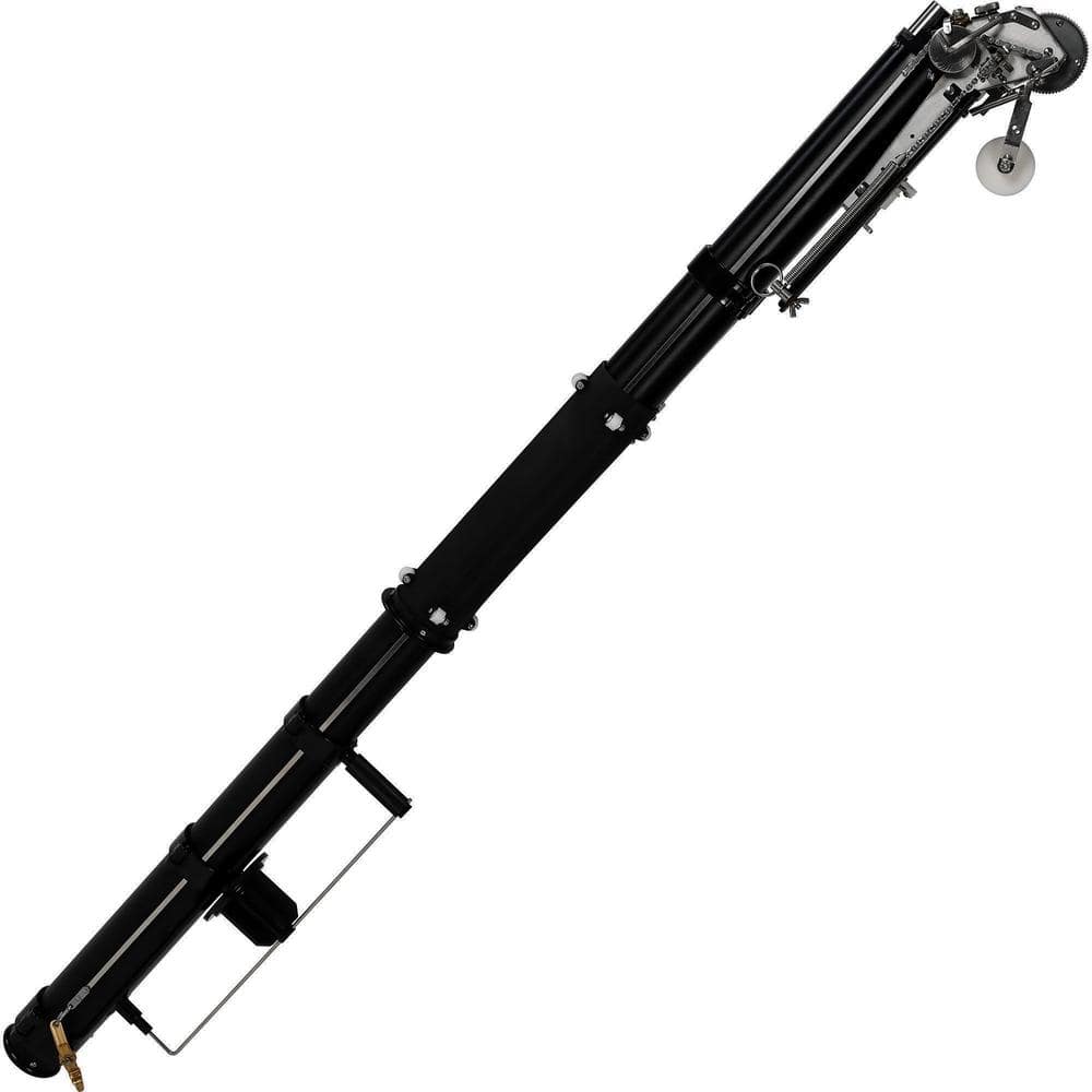
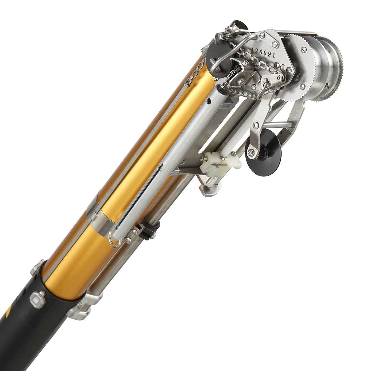
Bazooka Continuous Flow Taper - code T05CF.The Bazooka Continuous Flow Taper connects to the Continuous Flow Pump (CTPMP) to simultaneously apply drywall tape and the correct amount of joint compound to all types of drywall joints. The taper features an inline handle with dual trigger and weighs just 7 pounds. The new creaser wheel design and
DESCRIPTION:TapeTech 10 "" Continuous Flow Finishing Box - code CF10H.The 10 " TapeTech Continuous Flow Finishing Box is designed with the same look as the standard TapeTech EasyClean Finishing Box ™.Connects quickly and securely to the handles of the box continuous flow TapeTech to create a high-performance solution for finishing drywal
DESCRIPTION:TapeTech 12 "" Continuous Flow Finishing Box - code CF12H.The 12 " TapeTech Continuous Flow Finishing Box is designed with the same look as the standard TapeTech EasyClean Finishing Box ™.Connects quickly and securely to the handles of the box continuous flow TapeTech to create a high-performance solution for finishing drywal
DESCRIPTION:TapeTech 60 "" Continuous Flow Finishing Box Handle - code CFS8060TT.The handles for Bazooka continuous flow putty boxes feature the most ergonomic handle for size and shape and are up to 40% lighter than previous generations.Connecting without tools, with the TapeTech continuous flow finishing boxes, makes changing handles quick and ea
DESCRIPTION:Controller for putty boxes TapeTech CF Finishing Box Controller - code CTBXC.CTBXC is part of the Bazooka continuous flow gypsum plasterboard finishing system. It is attached to the handles for the putty boxes (T8034, T8042, T8054, T8072) to provide control of the wireless radio frequency (RF) of the flow of the mixture exiting the pump
DESCRIPTION:TapeTech Bazooka CFS 66 inch Corner Finisher Handle handle - code CFH66TT.The Bazooka Continuous Flow Corner Finisher Handles connect to standard TapeTech Corner Finishers to help you finish internal corners (angles) with remarkable speed and quality. The handles can also attach to TapeTech Mud Heads to continuously apply joint com
DESCRIPTION: TapeTech Bazooka CFS 42 inch Corner Finisher Handle handle - code T14CF. Bazooka Continuous Flow Angle Shaper handles connect to standard TapeTech angle shapers to help you finish interior corners with remarkable speed and quality. With a new, ergonomic shape of the handle, which makes it easier to grip and reduces fatigue.Atta
DESCRIPTION:Controller for anglers and tapers TapeTech RF Controller for Taper and Corner Finisher - code CTVLV.CTVLV is part of the Bazooka continuous flow gypsum plasterboard finishing system. Attaches to a taper (T05CF) and angle shaper handles (T14CF, T14EC) to provide wireless radio frequency (RF) control of the flow of the connection exiting
Continuous Flow Tool Fill Kit - code CTFIL.The Continuous Flow Tool Fill Kit is part of the Continuous Flow Drywall Finishing System. It attaches to the Continuous Flow pump (CTPMP) to allow goosenecks and filler adapters to be used to fill standard Automatic Taping and Finishing (ATF) tools. The Tool Fill Kit can remain connected to the pump after

© Copyright 2023. Pictures and descriptions are not to be copied or distributed without written consent from Great Lakes Taping Tools™. All Rights Reserved.
Installing and repairing drywall is easier when you have the right drywall taping tools. There are different tools for the various locations and types of drywall that you may be using. On eBay, you can choose from different manufacturers, types, features, and materials of drywall taping tools for sale at reasonable prices.
The available types of low-cost, fast drywall finishing tools include:Banjos: These are a handheld dispenser of drywall tape. There is a roller to hold the tape at an angle that is comfortable for the hand.
The taping tools for drywall are made from a range of materials, including anodized aluminum, which is used on the extenders, shafts, and handles of many tools. Stainless steel is another material used for those tool parts as well as the scrapers and blades. Some of the tools have plastic, rubberized, or silicone handles for ease of grasping. There are also drywall tools for sale that are made of brass, such as the loading pumps.
Priority is hereby claimed to U.S. Provisional Patent Application Serial No. 60/156,763 filed on Sep. 29, 1999, and U.S. Provisional Patent Application Serial No. 60/187,740 filed on Mar. 8, 2000.
The inventions relate to the field of pumps for pumping a slurry of grout to a remote location, tools for use at the remote location on a work surface. The inventions also related to control boxes and tools used for applying grout to a work surface in a controlled fashion. The inventions also relate to methods for accomplishing the foregoing.
There has been significant, but so far unsuccessful, effort in the prior art to construct group pumps, grout delivery systems, and grout applicator tools which provide for smooth and even application of grout to a construction surface. However, some of the prior art attempts to address the problem have yielded systems which either much be recharged with grout very frequently, thereby imposing a significant amount of down time and walking on the worker. Other prior art systems provide a continuous but uncontrollable flow of grout to the applicator tool, thus often oversupplying or undersupplying grout to the construction surface and resulting in an inferior finish.
U.S. Pat. No. 5,878,921 issued on Mar. 9, 1999 discloses a grout delivery apparatus with a flexible supply tube. The grout is supplied to a hand tool at a constant rate, although the rate may be pre-selected by the working through use of a switch.
U.S. Pat. No. 5,902,451 issued on May 11, 1999 discloses an applicator for wallboard joint compound. The applicator includes a control valve for controlling the flow of mud.
For the purposes of this document, the term “grout” shall include viscous materials used in the construction trades, such as drywall compound, plaster, paste, stucco, adhesive, glue, aggregate slurry, concrete, and other liquid and semi-liquid pumpable materials.
Grout is often used to fill in cracks, depressions, divots or defects in drywall surfaces. A particular problem faced by the drywall worker is how to apply a desired quantity of grout to a drywall blemish in a controlled manner, from a device that is maneuverable and efficient to use.
Accordingly, it is an object of some embodiments of the inventions to provide a pumping system and hand tool which deliver grout to a worker in usable amounts.
It is a further object of some embodiments of the inventions to provide a pump system which provides a continuously and automatically adjustable supply of grout to a remote location.
It is a further object of some embodiments of the inventions to provide a pumping system that maintains grout at a desired consistency, automatically adding water as necessary to provide thinner grout consistency.
It is a further object of some embodiments of the inventions to provide a handtool control box which may be used to apply grout to a work surface smoothly and in desired quantities.
It is a further object of some embodiments of the inventions to provide a grout pumping system that automatically mixes grout and water to a desired consistency before delivering it to a remote location for use.
It is a further object of some embodiments of the inventions to provide a handtool control box with a pressure-regulated valve that continuously adjusts the quantity of grout being supplied to a work surface.
It is a further invention of some embodiments of the invention to provide a handtool control box that automatically terminates grout flow when not in use.
These and other objects of the inventions will become apparent to persons of ordinary skill in the art upon reading the specification and viewing the appended drawings.
FIG. 1 depicts an automatic pump slurry system 1000 on a portable dolly 40. Main power cord 1 provides electricity to main power block 2 from which water pump cord 3 (FIG. 3) receives power for the water pump 4. The water pump 4 is depicted in FIG. 3 as well. The water pump 4 is pressure activated and turns on and off as needed to provide water to the system in order to keep the grout at a desired consistency.
A pressure sensor switch 6 is provided to keep the grout within the system pressurized so that the system is capable of providing grout to a remote location. Slurry sensor switch cord 5 plugs into the main power block 2 to receive electricity and provide it to slurry sensor switch 6. The toggle 7 of the pressure sensor switch is used to power the unit up for use and power it down for storage.
Referring to FIGS. 1, 5, 5 aand 5 b, when the slurry sensor switch 6 is turned on, it sends power through the motor cord 8, to the motor 9, which rotates the motor pulley 10. The motor pulley 10 turns the pulley belt 11 which rotates pump pulley 12 in order to power slurry pump 13. The slurry pump 13 forces a slurry of grout through pipe 14 apast check valve 15. Pump 13 may be any appropriate pump, such as the Moyno Progressive Cavity Pump Model 72201 GH from Moyno Industrial Products in Chicago, Ill. The motor 9 may be any appropriate motor such as the Emerson Model E514-TMP available from Emerson Electric Company, St. Louis, Mo. A gear box may be used with the motor, such gear box CBN2102S3136.MP1431 also from Emerson. The check valve 15 is a one-way valve which will not allow slurry to flow backward to the slurry pump 13. This ensures that any decrease in slurry pressure within the system can only caused by slurry escaping through the system pipe 14 a-14 cor system hose 20 aand 20 b(FIG. 2). Slurry pump 13 has a pump inlet 42 for receiving slurry from pump return 41 from the hopper 38.
The pressure within the system may be maintained within a predetermined range by pressure switch 6. An appropriate pressure switch is Model 25C1F2A available from United Electric Controls of Watertown, Mass. A high-pressure limit sensor (not shown) is set by the user by turning increase pressure screw 21, and is read by increase pressure sensor indicator 22. When slurry pressure in sensor pipe 18 increases to a sufficient level, it activates high-pressure sensor in slurry sensor switch 6, shutting off electricity to motor cord 8, turning off the motor and terminating further slurry pressure buildup. Electricity to motor cord 8 will then remain off until slurry escapes from the system, such as through system hose 20.
When slurry leaves the system, slurry pressure decreases thereby activating low-pressure sensor (not shown) in slurry sensor switch 6. The low-pressure switch is set by the user with low pressure screw 23 and is read by low pressure indicator 24. When slurry pressure decreases to the pre-set level, electricity to motor power cord 8 is turned on by the switch 6 in order to bring pressure up to the desired level, completing a cycle.
When fittings (further described in conjunction with FIG. 2) are connected, slurry can then flow to auger turbine 27, which powers auger 34. When switchover valve 43 ais open and work outlet 26 dis capped with cap 45 aslurry is forced into slurry consistency valve 46, which senses slurry consistency and automatically adds water to slurry when needed.
Slurry consistency is maintained by use of water pressurized by a water pump. Referring to FIGS. 1 and 3, water is fed to from water tank 56 through water pump inlet hose 57 to water pump 4. Water pump 4 will automatically sense the system"s need for water and begin pumping when necessary. Water is pumped through water pump outlet hose 58 through water inlet port 55. The water then blends with slurry and moves out to the hopper 38 thus creating a cycle. Cam lever 53 which is used to adjust consistency valve 46 and achieve the desired consistency of grout slurry.
FIG. 2 depicts hose and pipe connections, auger function and hopper dolly to pump dolly connection. System pipe 14 c(mentioned above), which is fed by the pump system, connects to system hose 20 aby hose connections 25 aand 26 a. System hose 20 aconnects to system pipe 14 dby hose connections 25 band 26 b. Pipe 14 dconnects to turbine 27(shown in FIGS. 13 and 10) which powers auger 34 (shown in phantom). Auger shaft bearings 35 aand 35 bensure easy rotation of auger shaft 33. As auger 34 rotates it mixes grout slurry and forces slurry toward slurry collector 36. This forces slurry to hopper valve 37. Hopper valve 37 is used to shut off slurry from hopper 38 while connecting or disconnecting hopper dolly mount 26 cto or from pump dolly mount 25 c.
When hopper valve 37 is turned on, slurry is forced through hopper mount 26 cand dolly mount 25 cand back to the slurry pump 13 (FIGS. 5 and 5b). When hopper dolly mount 26 cconnects to pump dolly mount 25 cit creates a ball and hitch setup like used on a truck and trailer. Hopper dolly mount 26 cacts as a hitch while pump dolly mount 25 cacts as the ball.
Bearing 44 allows hopper dolly 39 to swivel with respect to pump dolly 40. Hopper lid 78 keeps slurry from drying out or becoming contaminated with debris.
Slurry screen 61 screens slurry for smoothness. Swivel connection 62 allows tool connection 26 eto swivel with respect to work hose 20 b. Work hose valve 43 balso works as a faucet for turning slurry on and off to fill areas with slurry.
FIG. 3 depicts how water pump 4 is attached to water tank 56. Water is fed to water pump 4 through water inlet hose 57, which is gravity, fed by water tank 56. The water pump 4 then pumps water from the tank 56 to the hopper where it is utilized in the grout. The water pump 4 is pressure sensitive and is turned on an off as needed.
FIG. 4 depicts a pump dolly 40 used in some embodiments of the inventions. The pump dolly is used for transporting the system short distances, for loading and unloading the system, or moving the system over obstacles such as up or down stairs. Pump dolly 40 can be rolled in a horizontal position using rear pneumatic wheels/tires 63, and pulled by handle 64. Caps 45 band 45 care used to cap connections 25 aand 25 cwhen the machine is not in use.
FIG. 5 depicts pump dolly 40 when in a vertical position. FIG. 5ashows the motor 9 and FIG. 5bshows the slurry pump 13, apart from the assembled system on the dolly 40, for a better view.
When pump dolly 40 is in a vertical position it is pulled by handle 65. Pump dolly 40 can be rolled on all four wheels, including rear wheels 63 and front wheels 66. Front wheels are casters that may turn 360 degrees for easy handling, but may be locked in place by removing pin 67 from pin holder 68 and placing it in lock holes 69. Locking front wheels are useful when loading and unloading the machine.
FIG. 6 depicts consistency valve 46 in its closed position. Slurry enters through inlet 47 then passes through consistency ports 48. When slurry consistency is thin slurry passes through slurry consistency ports 48 with ease, putting no pressure on consistency piston 49 therefore leaving water inlet piston 50 in the off position, and allowing no water to mix with the slurry. However, the slurry is allowed to flow through consistency valve 46 and exiting through hopper return port 59. The pressure applied to push rod 52 exerts a corresponding force against water inlet piston 50, piston rod 60 and consistency piston 49 which, thereby regulating how much pressure is applied to consistency piston 49 before water inlet piston 50 clears water inlet port 55 and allows fresh water into the system.
FIG. 7 depicts consistency valve 46 in its open position. Slurry enters through inlet 47 then passes through consistency ports 48. If the slurry is thick it is restricted when passing through consistency ports 48, which puts pressure on consistency piston 49. That pressure moves piston 49 along bore 1001, and also moves water inlet piston 50 along the interior of the bore 1001 because the piston 49 and the piston 50 are connected by piston rod 60. hen water inlet piston 50 is moved far enough through the bore, it unblocks water inlet port 55 thus allowing water to mix with the slurry and exit through the hopper return port.
FIG. 8 depicts a parts explosion of consistency valve 46. Cylinder sleeves 70 aand 70 bare pressed into the bore 1001 of consistency valve 46. Water inlet ports 55 and 55 aline up creating a water passage. Water inlet seals 71 aand 71 bare show mounted on water inlet piston 50 to create a water-tight seal. Consistency piston 49 and water inlet piston 50 are connected by piston rod 60 and the entire unit is assembled in cylinder sleeves 70 aand 70 b. Next tension spring 51 is pushed into the cylinder sleeves, then pushrod 52 follows it. Next pushrod cap 72 is slid over pushrod 52 and threaded into cap hole 73 thus holding contents in place. Finally release grip 54 is threaded onto pushrod 52.
FIGS. 9aand 9 bdepict a cam lever 53 which is used to adjust consistency valve 46. FIG. 9adepicts the cam lever 53 in its thin consistency position. Cam lever 53 rotates about pin 74 in order to position push rod locks 75 to hold pushrod 52 and release grip 54 in the desired position with respect to the consistency valve 46. In the position depicted, the release grip 54 and rod 52 are in a position that will allow a greater flow of water through the consistency valve 46 in order to provide a thin consistency slurry. FIG. 9bdepicts the cam lever 53 in its thick consistency position. The cam lever 53 has been pulled away from the consistency valve, pushing the release grip 54 and rod 52 toward the consistency valve in order to cause less water to flow through the valve 46 and provide thicker consistency grout slurry. Push rod locks 75 hold cam lever 53 in place.
FIG. 10 depicts an internal view of auger turbine 27. The auger turbine 27 serves to force grout slurry to drive auger 34 (FIG. 1). Slurry enters the turbine 27 through turbine inlet 28. The slurry is under pressure and puts pressure on turbine fins 29, which turn turbine body 30. The slurry then exits through turbine outlet 31. Auger shaft 33 turns in conjunction with turbine body 30 thus rotating auger shaft 33. Turbine lid 32 screws in place on the turbine 27, creating a closed compartment so that slurry to travel in turbine inlet 28 and out turbine outlet 31. The auger 34 is rigidly mounted to the auger shaft 33, so that movement of slurry through the auger turbine 37 rotates the auger 34. The rotating auger 34 mixes the slurry to provide evenly mixed, consistent slurry.
In operation, the user places grout in the hopper and powers up the system. The grout pump will begin to operate, pumping grout to the turbine which turns the auger. The auger forces grout back to the grout pump.
The system keeps the grout a constant consistency by use of the consistency valve. When the grout becomes too thick or viscous, it forces open the consistency valve, and water is pumped by a water pump through the consistency valve into the hopper where the auger mixes it with the grout to reduce the viscosity of the grout.
When a user wishes to spread grout on a work surface, he or she must first turn off grout flow to the consistency valve. Then from a system hose, the user may withdraw pressurized grout. As grout pressure decreases in the system, the switch causes the auger to turn on and keep grout within the desired pressure range.
FIGS. 11-29 depict grout applicator control box and tools which may be used in conjunction with the grout slurry pumping system or separately as desired.
FIG. 11 depicts one embodiment of a joint compound applicator and control device of the inventions. Male cam and groove fitting 101 ais threaded onto slurry pipe 102 a. The pipe acts as a conduit for receiving grout from a pumping system and delivering it to an applicator control block such as 110. Slurry pipe 102 adelivers joint compound to female cam and groove fitting 103 a, which is threaded onto slurry pipe 102 a. The fitting 103 amay be connected by a user to a male fitting 101 bwhich allows joint compound to flow to brake housing 104. Brake housing 104 has a cavity which creates a channel within it (not shown) through which joint compound is fed to hose barbs 105 aand 105 b.
Control box hoses 106 aand 106 bare connected to hose barbs 105 aand 105 bwith hose clamps 107 aand 107 b. Joint compound is through control box hoses 106 aand 106 bto hose barbs 108 aand 108 b. The control box hoses 106 aand 106 bare connected to hose barbs 108 aand 108 bwith hose clamps 109 aand 109 b, which are threaded into control block 110. The prior sequence of parts creates a channel through which joint compound is fed from male cam and groove-fitting 101 ato control block 110.
A brake lever 111 (such as may be found on a bicycle) is mounted onto slurry pipe 102 a. A brake cable housing 113 is connected to brake lever 111. Brake cable housing 113 is connected to cable holder 112, which holds brake cable housing in place when brake cable 114 ais pulled. Cable stop 115 is connected to brake cable 114 aand attaches to brake lever hole 116. Brake lever pin 117 connects brake arm 118 thus creating a pivot point for brake arm 118 when female cam and groove-fitting 103 ais connected to male cam and groove fitting 101 b. Cable stop 1115 is connected to brake lever hole 116. The brake lever 111 can then be squeezed by a user, thus pivoting brake arm 118, which puts pressure on brake 119 and thereby the locking brake housing with pin 120.
Pin 120 is shown disassembled from control block 110. Pin 120 is pressed into pin holes 121 aand 121 band held in place with allen screws 122 aand 122 b. Brake housing 104 pivots with respect to control block 110. When a user squeezes brake lever 111, brake 119 is locked thus not allowing brake housing 104 and control block 110 to pivot. User uses this method to position control box 123 while holding slurry pipe 102 a.
FIG. 12 depicts how control box 110 functions. Joint compound is fed through hose barb cavity 124 through connection hole 125 and fills cylinder housing cavity 126 which has only three openings. One opening is on bottom of the control box 110 where cylinder housing 140 is attached. The other two are on each side of cylinder housing cavity 126 that create connection hole 125.
As joint compound fills valve including cylinder-housing 140 it is forced into cylinder ports 128, where it remains until control block 110 is forced downward by a user pressing it against a work surface. When this happens, piston 129 (which is connected to tool mount 135 through cable mount 136) is forced upward towards cylinder 130. As this happens, joint compound is allowed to flow through cylinder ports 128 and into control box cavity 131.
FIGS. 13a-13 cdepict the control box valve control box valve 1003. In FIG. 13a, the valve is disassembled. Cylinder housing 140 presses onto cylinder 130, which is secured by setscrew 141. Piston 129 is secured to cable 142. Piston ports 143 allow an escape of joint compound between piston 129 and top of cylinder 130 a, but the solid portion of the piston 130 will retard flow of joint compound. FIG. 13bdepicts the valve 1003 in it open position, and in FIG. 13bthe valve 1003 is closed.
FIGS. 14aand 14 bdepicts tool mount 135. FIG. 14adepicts a top view of the tool mount 135 and FIG. 14bdepicts a bottom view. Control box mount view ledge 145 slips inside tools that can be attached in order to create a seal. Control box mount screw 146 holds cable 142 (not shown in this Figure).
FIG. 15 depicts attachment of the control box 110 to the angle box attachment 147. Angle box attachment 147 mounts to control box 110 with hasp 39 and hasp receiver 148. Joint compound flows through tube port 149 to tube 150 and then to tube ball 151. Angle heads and various other attachments already on the market can attached to tube ball 51.
FIG. 7 depicts joint box 152 in disassembled condition. Wheel rod 154 mounts to wheel rod mounts 155 aand 155 b. Wheels 156 aand 156 bmount to wheel rod 154 with screws 157 aand 157 b. Blade mount 159 mounts to joint box 152. Blade receiver glides 160 mount to blade mount 159. Blade receiver 158 is allowed to flex between blade receiver glides 160 and joint box 152. Blade 161 mounts in blade receiver slot 162. Depth of blade 161 by adjustment screw 165. Blade receiver 158 is connected to slots 167 aand 167 bby shoes 166 aand 166 b. Arch of blade 161 is adjusted by blade adjuster 168 which puts pressure on adjuster pin 164 which pushes on blade receiver 158 which arches blade 161.
The foregoing structures permit the coating sheetrock joints with a preset amount of joint compound. Joint box flap 169 mounts to joint box 152 by slipping joint box flap 169 into flap slot 171. This creates a convenient way for the user to clean Joint box 152. Joint flap 169 is held in place by screws 172 aand 172 b. Joint compound flows through joint box 152 and out of coating slot 170.
FIG. 19 depicts blade adjuster operation. Adjuster lever 173 pivots on pin 174. This pivot action allows a user to put pressure on spring ball 175. When spring ball 175 is forced downward, spring 176 is compressed thus putting pressure on adjuster pin 177, which in turn puts pressure on blade receiver 158. As adjuster lever 173 is pushed downward, lever lock 178 pulls against adjuster lever pin 183 due to tension from spring 179, which is attached to blade adjuster 168 by spring pin 180. Lever lock 178 holds adjuster lever 173 in place until a user pulls lever lock handle 181 away from lever pin 182, thus allowing adjuster lever to be moved to a new position.
FIG. 20 depicts attachment of a control box 110 to an automatic taper attachment 1004. Control box 110 attaches to automatic taper 1004 with hasp 139 and hasp receiver 148. With control box 110 installed and control box door tension set (refer to FIG. 11), joint compound can then flow from control box 110 through gate inlet 183 through gate tube 184 (also shown in FIG. 22) and into gate port 185. Joint compound is then held in joint compound gate valve 186 until a user pushes tape grip wheel 187 against a work surface. When a user does this, grip wheel arm 188 pivots on pin 189. This causes cable receiver 192 to rotate and pulls on gate cable 190, thus pulling gate 191 which opens the flow of joint compound where it is then applied to tape through joint compound applicator 193.
A user operates the automatic taper by griping roller grip 194 with one hand and feeder/cutter grip 195 with the other hand. The user can then feed tape by pushing feeder/cutter grip 195 forward. As feeder/cutter grip 195 is pushed forward, feeder arm 198, which is attached to feeder/cutter grip 195, also moves feeding tape forward (also see FIG. 24). When a user pulls back on feeder/cutter grip 195, cutter rod 196 slides through feeder arm hole 199 and catches on cutter rod stop 200, which pulls cutter chain 197 a(shown and explained in FIG. 23). However when feeder arm 198 is pushed forward, cutter rod 196 slides through feeder arm hole 199, leaving cutter operations unaffected.
FIG. 21 depicts a cut-away view of a control box 110 attached to an automatic taper 1004. Tool mount 135 (FIGS. 12, 14 a& 14 b) slips into automatic taper mount 144. Tool mount ledge 145 (FIG. 14a) fits into automatic taper mount receiver 201 (FIG. 26) thus creating a seal. A user can set control box tension by pulling up on tension pin 202 thus pulling tension cable 206 aaround tension cable wheel 206 b(also shown in FIG. 25). When this happens, tension spring 104 (FIG. 25) expands creating a desired amount of tension on tension cable 203 b. Cable stop 203 aholds the cable in place. As this is happening, tension cable 203 bis pulled around tension wheels 206 aand 206 b(FIG. 25) that are connected to control block cable receiver 207. Due to tension on tension cable 203 b, control block 110 is pulled downward putting desired pressure on control block door 137 (FIG. 12), which allows control box 110 to operate in manner described above. Tension pin 202 can be removed and reinserted into tension pin slots 205 by the user. The tension pin 202 is held in place by tension created by tension spring 204 (FIG. 25). Tension is increased by moving the tension pin 202 to higher tension pin slots 205, and it is decreased by moving the tension pin 202 to lower tension pin slots.
FIG. 22 depicts an automatic taper 1005 with a roll of perfatape 301 installed. Essentially, this figure depicts the opposite side of the taper from FIG. 21. Perfatape 301 is installed on tape roller 208 by first removing secure pin 211 (FIG. 21), and then pulling tape roller pin 209 from tape roller holder 210 a, and removing tape roller 208 and tape roller holder 210 b. Perfatape 301 is reinstalled by inserting tape roller 208 into perfatape roll 301, then repositioning tape roller 208 in its original position, and inserting roller pin 209 through tape roller holder 210 a, tape roller 208, and tape roller holder 210 b. Secure pin 211 must also be reinstalled into tape roller pin.
Perfatape 301 is then allowed to spin on tape roller 208. Perfatape can then be pulled over tape catch 212, which keeps perfatape in its proper position. Tape is then inserted into tape slide 213 and fed to tape bridge 214, which ensures that tape extends to tape grip wheel 187 (see also FIG. 20). As user holding onto roller grip 194 can grip tape press lever 215 with a desired finger or fingers. When the user pulls tape press lever 215, it slides on frame tube 216. When this happens brake cable 114 bis pulled through brake cable housing 213 b, which is secured as described above. The brake cable then pulls tape press pulley 217 which is secured to tape press flipper 218, thus pivoting tape press flipper 218 on roll pin 219. This presses crease roller 220 against the center of the perfatape. This method is used to crease perfatape into angles and give user more control of perfatape.
Cable mounts 113 b, 113 c, 113 dand 113 ekeep the cable in position. Spring mount 222 keeps chain tension spring 222 taught in order to keep tension on the chain.
FIG. 23 is a cutaway partially exploded view showing a tape cutter and joint compound gate. When cutter chain 197 a(FIG. 10) is pulled across chain roller 225 b, cutter blade 221 being attached to the chain, slides through cutter blade channel 220 slicing the perfatape. Cutter chain 197 bis attached to cutter blade 221 and return spring 222 (FIG. 22). When a user releases feeder/cutter grip 195 (shown in FIG. 10), cutter chain 197 bis pulled by return spring 222 across chain roller 225 bthereby returning cutter blade 221 to a ready position.
FIG. 24 depicts the underside of a tape slide over which perfatape is fed. A user forces perfatape into tape slide 213, and past feeder needle 226 (which is secured into pivot rod 231 by needle screw 227). Feeder needle 226 is forced into a vertical position due to pressure from needle spring 233, which is secured to feeder arm 198. As feeder arm 198 is pushed forward, feeder needle 226 penetrates perfatape forcing it forward. When this happens, rubber finger 228 drags along finger catch 232 not affecting feeder operations. When feeder arm 198 is pulled backwards, rubber finger 228 falls into finger catch 232 forcing feeder needle 126 into a semi horizontal position and pulling feeder needle 226 out of the perfatape. Rubber finger 228 then slides along finger catch 232 in a backward position, thus keeping feeder needle 226 in a backward position, and allowing feeder needle 226 to glide over perfatape without pulling it out of position.
FIGS. 24aand 24 bdepict feeder needle 226, needle spring 233, pin rod 231, feeder arm 198 and rubber hinge 228 in the forwards and backwards positions, respectively.
FIG. 26adepicts the top of an automatic taper mount, and FIG. 26bdepicts the bottom of the same. Shown are automatic taper mount 144, gate inlet 183, and automatic taper mount receiver 201.
FIG. 27 depicts a joint compound gate valve 1010 in its closed position. When gate 191 is pulled by gate cable 190 (FIG. 23) (which is attached by gate cable screws 234 aand 234 b) gate 191 slides on gate ledge 138, which opens a channel 183 through which joint compound can flow. Joint compound then flows from gate inlet 183 to joint compound applicator 193. When gate 191 is in an open position, spring stop 237 pushes against gate spring 236. When gate cable 90 is released, pressure from gate spring 136 pulls gate 191 shut. Gasket 240 (FIG. 29) prevents leakage.
FIG. 29 depicts a parts explosion view of joint compound gate valve 1010 disassembled. To reassemble, push gate 191 and attached gate rod 235 through gate slot 241. Gate rod 235 slides through gate rod hole 240 and out the back side of joint compound valve 186. Then gate spring 236 can slide over gate rod 235 and be retained by spring stop 237. Blade slot 239 is provided as a channel through which cutter blade (not shown) can slide. Gate seal 242 and rod seal 243 ensure that joint compound does not leak around gate 191 and gate rod 135.
When a user desires to utilize the control box and tools to apply mud to a work surface, the following scenario is followed. Pressurized grout is made available to the control box. Within the control box, the pressurized grout fills the voids and receptacles. The piston of the control box valve will keep the valve ports closed and prevent mud from leaving the control box. When the user presses the control box and a tool attached to it against a work surface, the piston of the control box valve travels up in its bore exposing the valve ports, and permitting grout to travel out of the valve to the tool and to a work surface. The piston may be caused to travel up in the bore in variable positions depending on how much pressure the user exerts on the control box, thus controlling volume of grout flow. As grout flows out of the control box to the tool, pressure of the pressurized grout will drop, and if connected to pump system of the invention, the pump and auger will operate to increase grout pressure again, maintaining grout pressure within a useful pressure range.
The disclosures of U.S. Provisional Patent Application Serial No. 60/156,763 filed on Sep. 29, 1999, and U.S. Provisional Patent Application Serial No. 60/187,740 filed on Mar. 8, 2000 are hereby incorporated by reference.
While the present inventions have been described and illustrated in conjunction with a number of specific embodiments, those skilled in the art will appreciate that variations and modifications may be made without departing from the principles of the inventions as herein illustrated, described and claimed.
The present inventions may be embodied in other specific forms without departing from their spirit or characteristics. The described embodiments are to be considered in all respects as only illustrative, and not restrictive. The scope of the inventions are, therefore, indicated by the appended claims, rather than the foregoing description. All changes which come within the meaning and range of equivalency of the claims are to be embraced within their scope.


 8613371530291