
mud pump blows all 3 swabs manufacturer

Rig pump output, normally in volume per stroke, of mud pumps on the rig is one of important figures that we really need to know because we will use pump out put figures to calculate many parameters such as bottom up strokes, wash out depth, tracking drilling fluid, etc. In this post, you will learn how to calculate pump out put for triplex pump and duplex pump in bothOilfield and Metric Unit.

“Once you know these (rotary screw air) compressors, they’re pretty simple,” says Garth Owens, president of Drill Tech Drilling & Pump Inc. in Chino Valley, Arizona. “It’s not rocket science, but it is a precision unit.”
With approximately 15 rotary screw air compressors (two piston booster compressors) on six drill rigs or as auxiliaries on 10 pump hoists, Owens has learned the mechanical intricacies of them. He has rebuilt the compressors, changed their gear sets, and replaced them on rigs while passing along his knowledge to others in the industry.
“A lot of guys who are drilling don’t even have the right air to develop a well and they’ll throw a pump down there and just try to pump out the mud,” says Garth’s son, Nick, the manager at Drill Tech. “It destroys pumps and you’re never getting that mud wall cake off the walls behind the gravel pack to really get what the well’s producing.”
“You can drill too big of a well to where the annulus is too big, and you can’t get through the gravel pack to get the walls clean. That’s a big problem. A lot of guys think the bigger the hole they go, the more gravel the better, which isn’t necessarily good because you can never get enough annular velocity to get through the gravel pack and get that mud cake off. So, you’ve got to step back and look at the big picture of your annulus to your casing size to your gravel pack.
“Depending on what size drill pipe, what size borehole, what that annular space is between the drill pipe and the borehole determines the amount of your cubic feet per minute,” Garth Owens explains. “And then your pressure is determined by how deep you’re going to go. Every 2.31 feet of water is one pound of pressure you have to overcome, so basically, it’s a 2-to-1 ratio.
Today’s standard rotary screw air compressor rating is at least 900 cfm or 1000 cfm/350 psi. Thirty years ago, the standard was 450 cfm/250 psi or 600 cfm/250 psi.
For example, a 750 cfm/125 psi compressor is half the compressor of a 750 cfm/250 psi compressor because the contractor is compressing the air twice as tight. Therefore, with a 750 cfm/350 psi compressor, the contractor is compressing the air an additional 50%.
To help visualize it, Garth Owens likens pressurizing the compressor to a scuba tank getting pressurized rather than simply filling a balloon with static pressure.
“Instead of putting 125 pounds in it, in order to put 250 pounds in it, it takes a bigger screw and more horsepower to do that,” he shares. “And then to go to 350, it takes a bigger compressor and more horsepower to do that. So, every compressor has two numbers—cfm, and the second number is the amount of pressure that it puts out at that number.
“For instance, for a 750/125 compressor, it’ll probably take 125 horsepower to run that. You go to 750/250, it’ll take you 300 horsepower. You go to 750/350, it’ll take 400 horsepower to do the exact same thing because you’re compressing tighter, tighter, and tighter it takes more horsepower to overcome that pressure. So, the higher the pressure, the more horsepower you need.”
“Typically, ballpark rule of thumb, standard compressor is 125 to 150 psi,” Garth Owens says. “High pressure is 175 to maybe 200 psi. Extra high pressure is usually 350 psi and the highest you’ll ever go on a screw compressor is 500 psi. That’d be extra extra high pressure to get to 500 psi. Anything after that you’re running through a piston booster compressor and boosting pressure with a piston.
“When you get into the high-pressure compressors, it takes a lot of horsepower, takes a lot of heat, it builds up a lot of heat, and it burns a lot of fuel, so if the radiators aren’t clean, if the fanbelts are slipping, if the radiator is plugged up. . . .It might run great at 250 pounds; you push it at 350 and 30 minutes later the rig is overheated.”
To decrease the uphole velocity of 3000 feet per minute, some contractors use drill foam to clean the well at half the amount, 1500 feet per minute. “If you’re using foam and you’re filling that void, you’re taking half of that void away,” Garth Owens says. “You’re using half the air because you’re filling that void with an artificial substance. It’s going to foam up and blow out and then it’s going to evaporate and go away.”
The double-swabbed tool has perforations between the two swabs. Airlifting typically occurs through the drill pipe “from which the development swabs are suspended, so as the swabbing action brings suspended solids into the well, they are purged by the simultaneous airlift system,” writes Marvin F. Glotfelty, RG, in his book, The Art of Water Wells.
“The air comes out of the end of the drill pipe, comes up and hits that rubber swab which is the same diameter as the casing,” Garth Owens says, “and therefore all that air has to go out the perforations, blows into the gravel pack, spins that around in there, and cleans the gravel pack and cleans the borehole. Then the water comes up through the gravel pack and comes back to the perforations above your swab and comes out the top of the well.”
Glotfelty writes how this well development method is effective because “it provides both inward and outward energy to break down and remove the wall cake, without forming sand bridges in the adjacent formation.”
“We’ll actually create a vacuum and pull it between sections there,” Nick Owens says. “That’s why there’s a rubber swab above and below the holes. Typically, if you want to do an air swabber, you don’t need the rubbers because you’re just blowing it out through the perforated screen into the formation.”
The company’s high-velocity horizontal jetting tools allow it to adjust the amount of air it needs to push through them. “That way it’s blowing the air through the perforated screen, through the gravel pack, and then we’re trying to develop all that mud off there if it’s a mud hole,” Nick Owens says.
The company has an additional high-velocity jetting ball tool with approximately 20 holes each drilled to 3/16 inches around it. A high-pressure pump is used to pump freshwater down the well at 2000 psi.
“That will not only churn and turn that gravel, but it places that mud thinner all the way back to the borehole to knock off the wall cake,” Garth Owens says, “and once you’re done pressure jetting it, then you’ll come back and re-swab it and RC it all back out of there.”
Drill Tech, which had a backlog of approximately 100 wells and 30 pumps to install as of late July, stresses it all starts with the design of the well, drilling it correctly, using the right products, and not overusing polymers.
“If we’re RC drilling, we’ll mud up the top and then we’ll case the top off,” Nick Owens says. “There’s some wells out here where we live where the top 300 feet is all alluvium and there’s no water in it. We’ll mud those up, we’ll set a 300-foot surface casing, and we’ll RC drill the bottom out with just pure water because it’s just solid rock. So, we don’t use any product.
“We can literally drill a 1200-foot well, pull out, put our casing in it, and gravel pack it. You can trip in as soon as we’re done with zero development and can video the well, it’s that clean. Something of that nature doesn’t take much development because we didn’t put any product in the well. It just depends on where we are.”
To drive home the importance of using the correct amount of product, Nick Owens recalls a large drilling company that installed two large municipal wells 10 years ago in central Arizona. It both drilled with and pumped too much polymer into the wells and was unable to get the polymer out. The wells produced 300 gpm.
“We drilled some other wells near them, and we got 1200 gallons per minute out of the wells and the aquifer just simply because of the development and not using polymers,” he says, “so [it’s] a big thing to make sure of the product when you’re drilling and make sure you’re using the right product that you can get back out—that’s the biggest thing.”
“Most guys will just trip their drill pipe straight in, blow it straight up the hole, and they’re done,” he shares. “But you’ll get a lot more water out of your well, you’ll pump a lot less sand, and you’ll have a much better production well with a higher pumping level if you clean that formation out and get every bit of that mud that you put in back out again. The only way to do that is with pressure through the perforations.”
While drilling in July in California, Garth Owens also noticed large amounts of gravel being put into large diameter wells drilled using the mud rotary method. “They think that the bigger the hole is, the more gravel they put in, the better it is, which is not true. What they don’t get is the bigger the hole gets, the worse development job you can do.
“Let’s say you drill a 16-inch hole and put in 6-inch casing, and you’ve got 5 inches of gravel on either side of you, you cannot get enough pressure through 5 inches of gravel to clean the wall cake off the borehole on the outside to get it to produce. The well is still going to produce, but it would be a lot better producing well if it has 2 to 3 inches of gravel and you’ve got enough energy that you can push through that.”
Low-cost gravel too has its disadvantages, with it being crushed and therefore angular. These angular pieces all wiggle together and lock together like chip seal on a highway in the well, according to Garth Owens. This causes a slowdown in the production of water.
“Most people don’t use any chemicals to break down that wall cake because it costs $250 a bucket,” he says, “so we’ll go out and drill a well that will make 500 gallons per minute, and our competition literally on the next lot is drilling 100 gallons a minute. And it’s simply because of the gravel pack and the development process.”
“Time is one factor, they want to get to the next job,” Garth Owens says. “Another factor is they don’t want to put a swab in to pressurize the perforations. The third thing is purchasing the cheapest gravel they can because they think they’re going to overcome all that by drilling a hole that’s one or two inches bigger in diameter and now all that other stuff is irrelevant.”
Install the largest gravel to have the most square inches of opening and the least friction for the water to come through but stop the finest particles of sand.
“You design with maybe a 10 percent passing of sand,” he says, “and then you want to go down there and develop it until that 10 percent gets down to 0.5 percent or 0.25 percent. You want to airlift develop that until you’ve blown out everything, you’ve agitated it, washed out the gravel, washed off the wall cake, and then the ground itself and those fines come out of there.
“If you don’t do it right, you can spend three or four days pumping sand because the gravel is too coarse. You put in too coarse of a filter and the sand just keeps flowing. It takes forever, if it ever does stop. Too coarse of a sand and it’ll never stop.”
For a high-pressure compressor, there are three gears in the bellhousing and two low-stage screws and two high-stage screws. The simplicity allows the compressor to last for an average of 10,000 hours.
“Because on a piston compressor, you just have a receiver tank that just holds air,” he says, “and you can pressure it up to 250 to 300 pounds and jerk the valve open and that big surge of air is what blows out silts and rocks when it won’t do it when steady drilling.
“On a screw compressor, when you max out the pressure at say 350 pounds, and you’ve got the same pressure inside the filter as you do on the outside of the filter, when you blast that ball valve open, the pressure differential escapes faster inside than it can equalize. That’s what causes that filter to collapse and blow all your oil down your hose. That’s the one and only thing you don’t do with a screw compressor—build up to max pressure and jerk the valve open—that you can do with a piston compressor.”
For years, automatic transmission fluid (ATF) was the standard for lubrication on compressors. Today, synthetic compressor oil is used because they must run at about 225 degrees to 275 degrees to vaporize the water as it sucks moisture out of the air when drilling. “It sucks all that moisture into it and it rusts up all the bearings and gears,” Garth Owens says, “so by turning the thermostat up so hot, it vaporizes and burns the condensation out of it.
“You hear about a lot of rigs burning down and compressors burning down, it’s typically because they have old non-synthetic oil because it costs less,” Garth Owens says. “What happens is the tolerances are very tight in a screw compressor.
“Typically, there’s three thousandths max tolerant in a screw compressor, so you really have to keep your air filters clean, your oil filters clean, and your oil good. When that tolerance starts to get loose, when you start getting a bearing wearing out or one of your screws starts wearing into the impeller of the compressor, when that tolerance starts to get loose at all, typically your oil temperatures skyrocket tremendously. It’ll run at 200 degrees for 10 years and then all of a sudden, you’re wondering why it’s running at 275 degrees and trying to cook the hoses off your rig.”
The first indication is typically losing a bearing when the oil temperature begins climbing with the tolerances getting loose. “You either have steel on steel friction, or the tolerance is so loose that after you’ve compressed this air and oil, it scoops up the air and oil and pushes it through the screw,” Garth Owens says.
Check valves are used to isolate well-servicing equipment from high-pressure treating fluids during fracturing applications. Offered in three primary models, these rugged valves seal against a complete range of well-servicing fluids at pressures to 20,000 psi. Valves are available in 1-1/2 to 4-inch bore sizes for standard and reverse flow. Sour gas models available. Consult factory for configurations. Like all pressure containing products, Weco check valves require special handling.
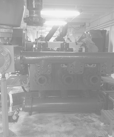
The 8-station manifold skid with Safety Iron connections provides users with a manifold system utilizing many of the design features of manifold trailers in a more compact footprint for use in regions where transport of larger manifold trailers is challenging. The manifold skid can be transported and loaded/unloaded from a flatbed trailer utilizing a winch. The modular design of the skid, coupled with the high pressure iron mounted above the low pressure manifold greatly enhances the serviceability of the high pressure system during maintenance cycles. The lower profile of the high pressure iron also increases safety for the user as actuating the isolation valves can be achieved more efficiently.
Cementing and circulating hoses can handle a complete range of standard and sour gas fluids at cold working pressures up to 15,000 psi. These rugged, all-steel hoses are available in 1 to 3-inch sizes and configurations to meet virtually any need. All materials meet ASTM or AISI standards.
Canam offers a full line of high-pressure integral union connections in a broad range of configurations and sizes from 2” through 4” and in pressure ratings to 15,000 psi NSCWP. Manufactured from high strength alloy steel forgings, integral union connections are available in lateral, tee, wyes, elbows, longsweep elbows and cross configurations.
Plug valves feature quality components for dependability, minimum weight, and maximum strength.The plug valves act as quarter-turn isolation valves, allowing operators to isolate portions of their flow line or specific pumping units from the entire pumping system in order to address pumping, operational or maintenance requirements.
In the pressure pumping industry, there is an inherent level of danger surrounding treating lines operating at high pressures. The potential for over pressure events exists, which could result in catastrophic failure of the treating line and result in SERIOUS BODILY INJURY, DEATH, OR PROPERTY DAMAGE. In order to avoid this type of failure, relief valves are commonly used on pressure pumping sites. Relief valves function by relying on the system’s hydraulic pressure to overcome a preset force in the valve, which then expels fluid through an outlet. Weir offers a variety of relief valve styles to help protect against over pressurization.
Swivel joints are available in nine basic styles or configurations. These styles permit 360-degree rotation and movement in one, two, or three planes. They can be combined in an unlimited variety of ways to suit practically any installation. All swivel joints are assembled using two or more standard pieces. Available in all grades.
Mud pumps are the heart of a drilling operation. TSM designs and manufactures extremely reliable and easy-to-maintain mud pumps, eliminating unnecessary maintenance and downtime.

Important Buyers Notice: All items are Sold"As-Is" with "No Warranty" expressed or implied. Items offered for sale may be damaged, inoperable and/or missing parts. You are strongly urged to carefully review each photo and video as well as personally inspect the item before making a decision to purchase. Free Oilfield Quote is not responsible for any missing or damaged equipment, part, item or accessory and shall not be held liable for any damage prior to or during the removal and/or delivery of the equipment. Any and all agreements contrary to the above disclaimer must be in writing and agreed upon up front and prior to any transaction.

United States Patent 3,450,412 WELL SWAB CUP Charles Haskell Collett, P.0. Box 411, Menlo Park, Calif. 94025 Filed Mar. 20, 1967, Ser. No. 624,350 Int. Cl. F16 15/48; B61f 15/22 U.S. Cl. 277212 11 Claims ABSTRACT OF THE DISCLOSURE A well swab cup with a molded nylon cage having cupreinforcing fingers.
The present invention relates to well swabs and more particularly to a swab cup of novel construction composed of a molded nylon cage or inner reinforcement on which is molded a cup-like body of rubber.
In the construction of well swab cups it is common practice to mold a rubber cup-like body with an internal reinforcing cage typically having a metallic ring or base thimble which supports a plurality of circumferentially spaced spring wire fingers. In use, one or more of such cups are disposed upon a swab body or mandrel which is adapted to be connected to a swab line to be run into a well. Fluid in the well, herein generally referred to as well fluid, including oil, water, mud or a combination of such fluids, will bypass the cup or cups as they move downwardly in the well, through the cups and around the cups, as well as through the supporting mandrel in the case of a valved mandrel. However, when the swab assembly is retrieved from the well, the bypass of well fluids i stopped and the cup is caused by hydrostatic pressure acting thereon to expand into tight sealing and sliding engagement with the well pipe Ibeing swabbed.
Of course, in "deep wells especially, the cup is subjected to severe wear conditions, depending upon the weight of the column of fluid being lifted by the swab, as the cup slides within the well pipe, and the reinforcement in the cup is adapted to protect the cup against wear as well as against being turned inside out or torn off of the mandrel.
While wire reinforcement fingers have been in long use they have not been altogether satisfactory due to the tendency of the rubber cups to tear from the wire fingers when the cup is heavily loaded and due to the tendency of the wire fingers to more or less locally flex into sliding contact with the well pipe, thereby causing undue local wear and ultimate failure.
The present invention, therefore, has an object the provision of a novel swab cup construction which includes a molded resilient plastic reinforcing cage which includes fingers spaced cirou-mferentially about the cup and defonrnable with the cup so as to engage the well pipe and reinforce the cup, the fingers having flexing characteristics compatible with the rubber cup and being wear resistant when in sliding engagement with the pipe.
Still another object is to provide a well swab cup having a molded plasitc reinforcing cage including circumferentially spaced fingers which adjacent their free ends are united by frangible elements, whereby to enable outward flexure of the upper margin or sealing lip portion of the cup when the swab assembly of which the cup forms a part is moved upwardly in the well pipe to be swabbed.
FIG. 3 is a view in longitudinal section as taken on the line 3--3 of FIG. 2, and showing in broken lines the loaded condition of the cup in the well pipe;
Referring first to FIG. 1, there is shown a swab cup S disposed on a mandrel M including a bottom guide 1 of any suitable construction and having an upper seating surface 2 engageable by the swab oup S when well fluid is being lifted from the well pipe, such as tubing 0r casing designated C. Customarily, the swab cup S is free to move on mandrel M so that as the assembly is being lowered in the pipe C, the cup S will be off of the seat 2, thereby allowing fluid to pass between the cup and the mandrel. In addition, the mandrel may have a passage therethrough having a check valve to allow the passage of well fluid therethrough "during downward movement of the swab assembly while closing the passage as the swab assembly is being retrieved from the well to lift a column of fluid from the pipe C.
Typically, swab cups of the type here involved comprise a body of elastomeric material, generically referred to as rubber, reinforced with a cage of wire springs or the like to prevent the rubber body from rapidly wearing and being destroyed by the heavy pressure applied thereto by the column of fluid being lifted from the well pipe.
The reinforcing cage R includes an annular base section 7 within the lower cup section 4, a plurality of ciroumferentially spaced elongate fingers 8 disposed in the intermediate cup section 5, and on alternate fingers re: duced section finger tips 8a which extend upwardly into the sealing lip section 6 of the cup body.
The base section 7 of the cake is downwardly tapered on its outer face, and on its inner annular face is provided with a rigid metal thimble 9 turned outwardly at 10 at its upper end to provide a flange and notched at 11 to interlock the thimble with the plastic cage during molding of the cage. The thimble 9 is adapted to prevent substantial outward deformation of the cup section 4, and if desired the outer portion of the cup base may be further supported by an outer metal thimble in a customary manner. The rubber material at the base section 4 of the cup covers the cage base 7 inside and outside and provides a seal portion 12 sealingly engageable with the seating surface 2 of the guide nut 1 on the mandrel M. The fingers 8 extend upwardly and slightly divergently from the base 7 of the cage R substantially to the lip section 6 of the cup body, and the rubber material fills the spaces between the fingers and covers both the inner and outer surfaces of the fingers.
At the sealing lip portion of the cup the finger tips 8a on alternate fingers 8, in the illustrative embodiment, form extensions of the inner surfaces of their respective fingers, but have a thickness or cross section less than the fingers. T"he finger tips 8a terminate within the sealing section 6, which provides a substantial annular rubber section adapted to establish initial sealing contact with the well pipe. Since the finger tips 8a are comparatively small in cross section, the sealing lip portion 6 of the cup may readily expand or flex outwardly under pressure to effect such initial sealing engagement. Moreover, such resilient flexing is enhanced by the fact that the finger tips 8a are on only certain of the fingers 8, in the illustrative cage R on alternate fingers.
As best seen in FIGS. 3 and 5, the cage fingers 8 adjacent their upper ends are provided with means normally holding them in predetermined spaced relation. This means comprises frangible webs 8b molded between the fingers during molding of the cage. Preferably, the webs 8b bridge the outer peripheries of the fingers. Such webs serve to not only fix the spacing of the fingers during molding of the rubber body on the cake, but also to establish the diameter about the fingers, thereby facilitating manufacture.
When the swab cup is in use, it will understood that the pressure acting inside the cup cavity will force the sealing lip 6 into :light sealing engagement with the pipe as the swab is being retrieved. In addition, the intermediate section of the cup will be deformed, approximately as shown in broken lines in FIG. 3, so that the frangible webs will be broken to allow outward flexure of the reinforcing fingers in the cup. At their upper ends, the fingers 8 are bevelled at 8c at such an angle as to assist in causing the cup to flex inward when passing the downwardly facing pipe shoulder in the usual casing joints, as shown in FIG. 1.
Under heavy fluid loads, the fingers 8 will bend substantially in the rubber body so as to move outwardly toward the pipe wall. However, nylon for example has a good recovery rate and the cup will return to its original form after use to enable reuse through a substantial number of runs under ordinary well pipe and other environmental conditions.
1. A well swab cup comprising: a cup-like body of elastomeric material, a reinforcing cage molded in said body, said cage being composed of resilient plastic material and having a unitized annular base with a plurality of circumferentially spaced fingers extending upwardly from said base.
References Cited UNITED STATES PATENTS 1,548,580 8/ 1925 Christensen 92-241 1,563,164 11/1925 Christenson 92-241 1,767,936 6/1930 McElroy et al. 277-231 X 2,336,090 12/1943 Granger 92-241 2,358,908 9/ 1944 Crickmer 92-241 2,581,981 1/1952 Taylor 92-241 X 2,852,323 9/ 1958 Bowerman 92-241 X 2,887,347 5/1959 Losey 92-241 3,094,904 6/ 1963 Healy 92-241 3,152,809 10/ 1964 Waldrop 277-212 3,346,267 10/ 1967 Farley 277-233 X CARROLL B. DORITY, Jr., Primary Examiner.

This article describes the causes of and steps to prevent clogging and/or damage to septic pumps, grinder pumps, and sewage ejector pumps. We include excerpts from sewage or septic grinder pump manufacturers" installation manuals that describe sewage pump diagnosis & repair procedures.
This article series also lists septic and grinder pump types, brands, and will identify pumps that are resistant to damage from debris or objects that may enter the toilet, sewer line, or septic tank.
InspectAPedia.com readers report troubles with several types of septic pumps, sewage pumps, and grinder pumps, both for sewage ejector pumps located in the home (such as to pump a basement toilet waste line up to a higher main drain) and for pumps that operate septic or graywater tanks.
Septic pump damage may occur from certain objects that enter building drains regardless of where and how the pump is used, including in-building sewage ejector pumps (shown at left) or pumps used in septic tanks or septic effluent tanks.
Some of the items in this list won"t damage the septic tank itself as their volume is small and they don"t usually block the septic piping or baffles, but if your septic system or even public sewer connection use a septic pump, grinder pump, or sewage ejector pump, the items listed here can clog and damage or even destroy a sewage pump, leading to costly repairs.
Watch out for the following conditions that cause clogging and even burn up of various types of sewage pumps, grinder pumps, ejector pumps, and septic pumps:
Cigarette butts are not biodegradable and should not be flushed into the septic system. And the filters on cigarette butts can clog and destroy septic pumps.
Condoms won"t clog a pipe but like some other debris, because they are of modest size and are quite flexible, but condoms are (usually) not bio degradable. So we listed condoms, or other latex products such as latex gloves above as "never flush".
A condom in the septic tank will probably join other debris in the tank"s floating scum layer, and will be removed at the next tank pump-out. Of course, if the septic tank outlet tee baffles are missing, the condom will join other floating debris on its way out to clog the drainfield, so ask your septic pumper to check the condition of the septic tank baffles when the septic tank is next pumped.
BUT if your system uses a septic pump or grinder pump or sewage ejector pump, this material can clog the pump impeller and cause expensive pump damage or motor burnout.
Cotton swabs (Q-tips®) have been known to clog a drain or two - cotton is not readily biodegradable, though cotton swabs are trivial in volume and are not important in the septic tank itself.
BUT if your system uses a septic pump or grinder pump or sewage ejector pump, this material can clog the pump impeller and cause expensive pump damage or motor burnout.
Disposable wipes - such as baby wipes or personal hygiene wipes, even products described as "biodegradable" or "OK for use in septic systems" may NOT be OK: if your system uses a septic pump or grinder pump or sewage ejector pump, this material can clog the pump impeller and cause expensive pump damage or motor burnout. S
The following Common Sewage / Septic Pump Problems and sewage pump (septic grinder pump) diagnosis & repair advice is adapted from installation manuals from manufacturers & from other sources.
Vent opening at check valve: Zoeller Pump provides a combined union/check valve, the "Unicheck". The company notes that with this valve is installed, the installer must drill a 3/16" (5mm) vent opening in the discharge line at a height even with the top of the pump.
Zoeller Pump Company, "Installation & Service Instructions, 803/805/807 Grinder Pumps", [PDF] Zoeller Pump Co., P.O. BOX 16347 • Louisville, KY 40256-0347, Website: Zoeller.com Retrieved 2016/04/05, original source: http://www.zoellerpumps.com/en-na/product/1242-#documents
Zoeller Pump Company, "Installation Instructions, Recommended Models, Effluent/Sump/DeWatering & Sewage[pumps]", [PDF] Zoeller Pump Co., P.O. BOX 16347 • Louisville, KY 40256-0347, Website: Zoeller.com Retrieved 2016/04/05, original source: http://www.deanbennett.com/53-install-inst.pdf
Nearly all authorities warn that acids or other chemicals might harm a septic system (I agree), and some chemicals may harm the seals in the grinder pump system as well.
However, a review of seven most-widely cited grinder pump and sewage pump advisory papers or instruction sets found that not one of them specified the actual level of acidity that would or would not be harmful to the pumping system.
That leaves us to make a reasonable guess at the answer: sufficiently diluted, an acid-based toilet cleaner should not harm either the pump or the septic system.
I pose that occasional use of a toilet stain remover (often including acids), used as directed, will be diluted enough to avoid such harm. You can reduce the risk of grinder or effluent pump damage further by additional dilution of the acid-based cleaner: try 2 or three additional flushes to dilute and then remove the acidic cleaner from the grinder pump reservoir.
Subsequent normal daily use of the sinks, showers, tubs, and toilets connected to the septic or sewage pump will further dilute any acidic content in the pump reservoir to a harmless level.
Watch out:flushing any acid into a residential sewage grinder pump or septic effluent pump that subsequently remains un-used for days, weeks, or longer, might risk damage to the pump components because in that case the acidic solution may remain in contact with pump parts for a prolonged interval.
At that level of usage and when further diluted by water as the toilet is flushed, even in the first flush the 6 oz. of solution (hazardous acidic) is diluted in 1-2 gallons of water or more (depending on toilet design and flush quantity).
In three flushes or 3 gallons total, you have diluted the original acidic CLR cleaner to 1% of its original strength. Even without knowing the actual level of acidity of the product as sold in the container, this is likely to be so dilute as to be harmless to the pump.
Emergency Overview: WARNING: EYE IRRITATANT. GHS Toxicity Category 2A Causes eye irritation and possible SKIN IRRITATANT GHS Category 3 – on sensitive skin.
which helps eliminate condensation and freezing. - GRINDER PUMP FAQS for CT [PDF] Groton Connecticut Department of Public Works, retrieved 20178/06/19, original source: http://www.groton-ct.gov/depts/pubwks/docs/Grinder%20Pump%20Website%20info%20the%20hurricane.pdf
Heather, sewage ejector pumps normally are operated by a float control switch. As wastewater rises in the holding tank when the level is high enough the float switch turns the pump on.
So if your sewage pump never turns off, presuming it"s properly wired, the float switch is either stuck on debris in the holding tank, or the switch needs to be replaced.
The green arrow in our sewer pump float switch example is the actual switch assembly that turns the motor on and off as the float, on its shaft, rises and falls vertically. Image source: plumbingsupply.com [4]
Take a look at the two most common sewage float switch types in our Little Giant™ sketch above and the Zoeller™ sewage pump and control switch image at left. Your switch probably looks like one of these two types.
In a few rare instances I have found homes at which the ejector pump float switch had failed and the owners, rather than replacing the switch, just hard-wired the pump to turn on and off by a manual switch.
This is a bad idea for obvious reasons including inconvenience and the risk that either the pump is left on longer than necessary or left off leading to a sewage backup.
Watch out: in addition to obvious bacterial hazards at sewage pumping stations there are methane gas hazards of explosion and asphyxiation - don"t work alone. Also see our list above of things that can clog up or damage a sewage ejector pump.
Is your sewage ejector pump already damaged? Maybe not. Some sewage pump models indicate in the installation and maintenance manual that the pump can tolerate being run "dry". But best practice is to set the float control switch so that the liquid level does not drop below the pump body.
The Little Giant™ remote float control switch (left) can be used as an auxiliary control / warning device on sewage and sump pump ejector installations to control an alarm.
By mounting this switch at an activation position higher than the normal float switch that controls pump operation, this remote control switch can activate a light or audible alarm to warn building occupants that the sewage system is not being emptied.
I don"t like the idea of these sewer ejection pumps as they suck electricity, i feel my builder dug the foundation too deep and therefore stuck me with this annoyance on my new home.
Dave you can figure out just how much electricity your ejector pump is using either by some careful examining of the electric meter itself or by looking up the specs on your motor.
Normally these motors run only intermittently. I"d be surprised if the ejector pump was using as much overall electricity in watt-hours as your refrigerator, freezer, or air conditioner.
The septic pump float switch at left describes a common sewage pump control method used on Little Giant™ and many other submersible sewage grinder pumps.
This type of sewage pump float switch, also used on lots of sump pumps, swings in an arc between its high and low positions. It"s a simple, reliable electric switch, but debris in the holding tank or improper tethering can lead to switch jamming.
Note that by moving the tether position of the float wire in the pumping chamber you can adjust the pump cut-in and cut-out wastewater levels in the holding tank. Sketch courtesy of plumbingsupply.com [4]
What do you suppose was the large white waxy clumpy substance that I found recently in my septic pump container? The sticky substance was stuck to the sides of the tank (where it was several inches thick).
It was also stuck all over the septic pump, and stuck all over the float switch - .which of course was the problem and the reason for opening the tank.
[Click to enlarge any image] Photo: white waxy deposit clogging the inlet of a sewage ejector pump - InspectApedia.com photo from an anonymous reader.
Eboigbodin (2008), and McBain (2003) as well as many other researchers cite the role of bacteria and fungi in the formation of biofilm slimy deposits in water supply and drain piping systems.
Common among the biofilm organisms are the fungus Fusarium sp. often detected in plumbing drains (Short 2011), Pseudomonas aeruginosa, other bacteria, as well as yeasts such as Rhodotorula mucilaginosa (usually red or orange) or Exophiala dermatidis (a black yeast) spread from dishwashers to kitchen. - Zupančič 2016
Bacterial growth clogging in a drain line, drain trap, or in an ejector pump or sewage pump can be aggravated by extra sources of bacteria such as bacteria forming in air conditioning condensage dispensed-of by dripping it through the condensate drain system into a seldom-used trap or sewage pump chamber.
A good guess is that your sewage ejector tank or septic tank that uses a septic pump was clogged by someone who used too much powdered detergents in a clothes washer or dishwasher.
It"s well established that using excessive amounts of powdered detergent in a dishwasher or clothes washer can lead to accumulation of a gooey mess that clogs drains or even septic drainfields. Some bar soaps can also form waxy clogs or blockages in plumbing systems and sewage or effluent pumps.
You have provided another important example: excessive detergent use OR using a budget detergent that contains large amounts of clay fillers can clog the pump float control switch or the pump intake in a sewage ejector pump or sewer pump as well.
Soaps produced using sodium hydroxide are referred to as "hard" soaps that are more-difficult to dissolve in water, while soaps produced using potassium hydroxide tend to be more-easily soluble and are thus called "soft" soaps.
Yep it"s true, some fools dump plaster or drywall dust and debris down toilets or other drains while cleaning up after a plastering or drywall installation or repair job.
Don"t do that. Both plaster and drywall dust will form a hard-to-remove drain blockage in nearby traps or drain lines. While acid-based drain cleaners might remove such blockages more-likely you"ll need to use a power snake or other mechanical drain cleaning system.
Other waxy clogging can be traced to soaps and detergents: this second common cause of waxy deposits that clog pumping chambers or piping are fats and oils that were flushed down drains.
For residential drains and pump suffering from fat or oil clogging waxy deposits, plumbing drain FOG (Fat Oil Grease) degreasers (such as Cloroben PT-4) may help dissolve the clog.
Some Hercules products such as Hercules PT-GIO1™ combine grease solvents and "waste digesting bacteria" while Hercules PT-4 (or Cloroben PT-4) is a formula designed to rapidly dissolve FOG (Fats Oils and Grease) using a non-acidic, non-caustic formula that is described as "safe on all types of piping materials when used as directed"
If your water is "hard" or high in calcium or magnesium that condition, combined with those types of soap particularly invites the formation of waxy white blobs that clog drains, traps, and septic pumps.
Her plumber cut-out and replaced the clogged trap as well as the most-clogged nearby PVC drain lines and physically removed wax deposits in the downstream drain opening.
You may need to replace the worn, corroded anode rod in your water heater and you may need to have your water tested and if it"s sufficiently alkaline, you may need to install a water treatment system.
Bédard, Emilie, Michèle Prévost, and Eric Déziel. "Pseudomonas aeruginosa in premise plumbing of large buildings." MicrobiologyOpen 5, no. 6 (2016): 937-956.
Eboigbodin, Kevin E., Allyson Seth, and Catherine A. Biggs. "A review of biofilms in domestic plumbing." Journal‐American Water Works Association 100, no. 10 (2008): 131-138.
However, drinking water should also meet the necessary quality requirements at the point of consumption even though domestic plumbing systems are usually not constructed from the same materials that are used to construct distribution systems.
Fleming, I. R., and R. K. Rowe. "Laboratory studies of clogging of landfill leachate collection and drainage systems." Canadian Geotechnical Journal 41, no. 1 (2004): 134-153.
McBain, Andrew J., Robert G. Bartolo, Carl E. Catrenich, Duane Charbonneau, Ruth G. Ledder, Alexander H. Rickard, Sharon A. Symmons, and Peter Gilbert. "Microbial characterization of biofilms in domestic drains and the establishment of stable biofilm microcosms." Applied and Environmental Microbiology 69, no. 1 (2003): 177-185.
Drain biofilms harbored 9.8 to 11.3 log10 cells of viable enteric species and pseudomonads/g, while CDFF-grown biofilms harbored 10.6 to 11.4 log10 cells/g.
Since live-dead direct staining revealed various efficiencies of recovery by culture, samples were analyzed by DGGE, utilizing primers specific for the V2-V3 region of eubacterial 16S rDNA. These analyses showed that the major PCR amplicons from in situ material were represented in the microcosms and maintained there over extended periods.
Sequencing of amplicons resolved by DGGE revealed that the biofilms were dominated by a small number of genera, which were also isolated by culture. One drain sample harbored the protozoan Colpoda maupasi, together with rhabtidid nematodes and bdelloid rotifers.
Zupančič, Jerneja, Monika Novak Babič, Polona Zalar, and Nina Gunde-Cimerman. "The black yeast Exophiala dermatitidis and other selected opportunistic human fungal pathogens spread from dishwashers to kitchens." [PDF] PLoS One 11, no. 2 (2016): e0148166. Retrieved 2018/07/04, original source: http://journals.plos.org/plosone/article?id=10.1371/journal.pone.0148166 Creative Commons Lic.
We investigated the diversity and distribution of fungi in nine different sites inside 30 residential dishwashers. In total, 503 fungal strains were isolated, which belong to 10 genera and 84 species. Irrespective of the sampled site, 83% of the dishwashers were positive for fungi.
Comparison of fungal contamination of kitchens without and with dishwashers revealed that virtually all were contaminated with fungi. In both cases, the most contaminated sites were the kitchen drain and the dish drying rack.
We have a Zoelner grinder lift pump that recently clogged with toilet paper when to wrapped around the impeller. Are there any recommendations for what type of TP is best to prevent these types of problems?
Thomas I"ve been testing toilet paper breakdown rates for almost a decade - one experiment is long-going; my OPINION is that all toilet papers break down just fine in a septic tank itself - changing the paper brand won"t reliably fix the problem you encountered.
So I suspect there"s a different problem: the grinder - tampons, or some other stuff can clog up sewage pumps. (Dental floss is one of the worst offenders and it"s hard to keep that out of the pump).
But Zoeller indicates quite clearly that their residential sewage grinder pumps, such as the Zoeller Shark 803/805/807 Residential Grinders can handle "all flushable wastes" - to me that means feces and toilet paper but not tampons and probably not dental floss.
Are we sure you have the right pump type and model installed. Sometimes people install a de-watering sump pump or a simple effluent lift pump where a grinder pump is needed.
Zoeller"s sewer pump instructions also point out that a role of the pump chamber cover is to prevent debris from entering the pumping chamber from that direction as well.
Watch out: at SEPTIC & SEWAGE PUMPS we explain that choosing the wrong type of pump, such as installing a simple basin pump or effluent pump (designed to handle primarily liquid waste) on a system where blackwater (toilet waste) is entering the system is likely to lead to pump clogging and failure.
I"m glad you recognize that all we have is an opinion since we"re not on site and there may be important details that we can"t see and don"t know about this problem.
I would be tempted to try to fish with a small hooked wire, working very carefully so it"s not to push the broken off brush tip further down the drain but to see if I could hook it and drag it back out.
I let water run in the tub several times and flushed toilet few times with pump working. Only option is to call sewer service contractor to inspect the sump pit while flushing to see any thing comes or look inside. Your expert opinion is much appreciated.
I have 3 year old Ashland Sewage pump model SW50 working well . I attempted to clean the tub drain which is connected to the sewage pump along with toilet. I was using Sink Wizard with specially hardened bristle tips, when it apparently got broken and bristle tip is gone, it is about 3/4" long.
Because there is no way to get access to p tap if any , will get in the sewer pump and give any problem?. Should I call plumber and sewer service to inspect the sewer tank to retrieve the piece or if it is stuck in the p tap, should I continue use the bath tube so that it will be flushed in to the sewer tank and pumped out without causing any damage to the pump?
I am puzzled too as I don"t know exactly how leaving the pump powered off for a time would cause a banging noise when it"s plugged back in. I would probably start by visual inspection including looking at how the pump is secured and looking for loose components
My grinder pump alarm went off yesterday and the light was red I went out and noticed that one of the plugs had been unplugged by a contractor working at my property I immediately plugged it back in and the light went off 10 seconds later but now I have a banging noise that"s coming from right underneath with a grinder is I have no idea what it is...
You need a grinder pump to move wastewater, including solids, out of your in-home pumping chamber out to your septic tank. That 50 gallon pumping station cannot work if all solids remained in such a small space. (Seems obvious; I"m not a sanitary engineer).
I have a septic mound system with a two compartment concrete 1000 gallon tank and my home is below the tank as the property is uphill. All the drains collect into a 50 gallon fiberglass holding tank in the basement and is ejected by a Weil brand single phase 1 hp 230v 1750 rpm grinder pump (yes, grinder pump) the run (I think called total dead head)including all horizontal and vertical distance is approx 60 feet .
My question is, was it appropriate for the builder to install a grinder pump when it seems grinder pump use is almost universally frowned upon in septic systems due to the slurry the grinder makes being difficult to separate into solids and liquid components that septics need to operate effectively without clogging the field.
Should I pull the grinder pump and install a comparably spec’d sewage ejector pump or is there certain situations that might require or benefit from the grinder pump. I can’t get a straight answer from anyone, please help with some advice if you can.
It might be if it"s the wrong pump for the application. For example if you need a grinder pump and you don"t have one with the capacity then it may be clogged and destroyed
I have been using sewage pump for lower portion of the property for 3 years. This pump generally takes care of regular use of one kitchen and bathroom. In the last year and a half, it started to have deposits coagulate at the bottom of the sewage pump and every 5 to 6 months, we have to clean it to avoid clogging. What could be the reason?
If the unfortunate event of a few non-flushable wipes going down the toilet drain has *already occurred*... will pumping the septic tank resolve the potential problems and remove the unwanted material?
I am sorry to have to offer what"s an annoying guess but I suspect that if toilet paper is accumulating at all in the sewage ejector pump basin then the wrong type of pump may be installed.
I live in a basement with a sumppump sending waste up to the sewer. Toilet paper hardens on the ball if I am gone for a few days. What can I use to keep waste soft and flowable
The number of companies selling septic additives and "cleaners" is nearly equal to the population of Indonesia; at SEPTIC TREATMENTS & CHEMICALS https://inspectapedia.com/septic/Septic_Tank_Treatments.php we describe some of these and explain that they are generally not needed for proper septic TANK maintenance.
However there may be reasons to clean the sewage ejector pump and pumping chamber. Narrowing the search to those products gives some suggestions such as Core Biologic"s Ejector Tank Treatment https://www.corebiologic.com/ejectortanktreatmenthh
We had our system alarm "go off" about a week ago on our detached dwelling unit (with grinder pump) it turned off after about 3 minutes and after some testing it appears to be in working order. I did a light snaking off the drains and surprisingly a bunch of dental floss came up (disgusting and concerning all in one) along with some of the "grey matter" you wrote about above. So I am wondering if there is a product or substance that I can put down the drain periodically that will help keep the system "clean"?
If you"re referring to the aerator pump on an aerobic septic system most of those are designed to run continuously occasionally there"s some designs that use a timer. If you leave it off your system is going to a backup or you"ll damage the drain field.
You can remove some grease type sludges with non-caustic treatments such as the Clorben PT product series. I"d check for a sticking control float that is not switching the pump on when it should.
A yellow sludge builds up on the float and won"t let it ride up to make the switch located on top of cover come on. I have to take out one of the infeed pipes and blasg it off with hot water from our water heater. It"s located in the basement and puts out an odor. I"d like to know what I could treat it with to dissolve this sludge without damaging the pump.
I have a cajun air septic system and the high water alarm is on and the pump is running but not pumping and i looked inside and the water inside the tank isn"t high enough to pump water
the pump impeller may be damaged or partly clogged. Sometimes a clog will separate itself when power is off, the pump can run for a time, then the clog is drawn back.
Over the summer we noticed an odor outside, opened the cover of the pit to see the water/sewage level almost to the top of the pit about 3 feet deep. The pump was running but not ejecting the sewage.
The pump worked fine and ejected the wast and shut off. Have been keeping and eye on it and now almost daily the container is full, pump is running but not ejecting and I simply unplug it, lift pump couple times and plug it back in, it ejects until pit empty and turns off like it should, however next day it is the same thing, full and running but not ejecting.
No question that tampons and the like can clog ejector and sewage pumps. Besides posting "Don"t flush" signs, which are never 100% effective, one might need to install a pump whose manufacturer says can handle those obstructions. Screens clog.
We have a small business with several toilets and sinks. Our sewer line runs to a jointly owned pump vault (our sewage and our neighbor"s). We have a dual-pump (ejector) system in the vault that pushes the sewage up and down a pressure line (down a side street) to the City"s main in a major cross street.
A new business took occupancy of the neighbor building a year ago (we"ve been here for more than 25 years), and over the past year we"ve had nothing but trouble with clogged pumps
Typically feminine products and other debris. If this were solely the neighbor"s problem, we"d let them suffer through it, but they"ve made it our problem. Do you have any suggestions of a macerator/grinder that we could place in-line and up-stream from the pumps? And/or is there another solution you would recommend? All suggestions appreciated. Thanks
The pump shut off last night so I just did a load of laundry now it looks like the pump isn"t working at all as the downstairs toilet bowl is complete full. We still cannot figure out how to get the lid off this thing and my husband knows a lot about plumbing but not this sewage pump.
So we are still wondering how to get the lid off this thing. It look similar to the hand drawn picture above which says Basic Environment One Grinder pump.
Continue reading at SEPTIC PUMP INSPECTION & MAINTENANCE or select a topic from the closely-related articles below, or see the complete ARTICLE INDEX.
SEWAGE PUMP DAMAGE & REPAIR at InspectApedia.com - online encyclopedia of building & environmental inspection, testing, diagnosis, repair, & problem prevention advice.


 8613371530291