
mud pump blows all 3 swabs quotation
Important Buyers Notice: All items are Sold"As-Is" with "No Warranty" expressed or implied. Items offered for sale may be damaged, inoperable and/or missing parts. You are strongly urged to carefully review each photo and video as well as personally inspect the item before making a decision to purchase. Free Oilfield Quote is not responsible for any missing or damaged equipment, part, item or accessory and shall not be held liable for any damage prior to or during the removal and/or delivery of the equipment. Any and all agreements contrary to the above disclaimer must be in writing and agreed upon up front and prior to any transaction.
The Well Control System or the Blowout Prevention System on a drilling rig is the system that prevents the uncontrolled, catastrophic release of high-pressure fluids (oil, gas, or salt water) from subsurface formations. These uncontrolled releases of formation fluids are referred to as Blowouts. Due to the explosive nature of oil and gas, any spark on the surface can result in the ignition of the fluids and an explosion on the rig. An explosive blowout and the failure of the Well Control System were the causes of the Mocondo Well disaster that killed eleven of the rig crew on the Deep Water Horizon Rig on April 20, 2010 and resulted in 35,000 to 60,000 bbl/day of crude oil to spill into the Gulf of Mexico. We will discuss this later in the lesson.
The blowout preventers are the principal piece of equipment in the well control system and are operated hydraulically; pressurized fluids are used to operate pistons and cylinders to open or close the valves on the BOP. The Accumulators (Item 18 in Figure 9.02) are used to store pressurized, non-explosive gas and pressurized hydraulic fluid to run the hydraulics systems on the rig. The accumulators store enough compressed energy to operate the blowout preventers even if the Power System of the rig is not operating.
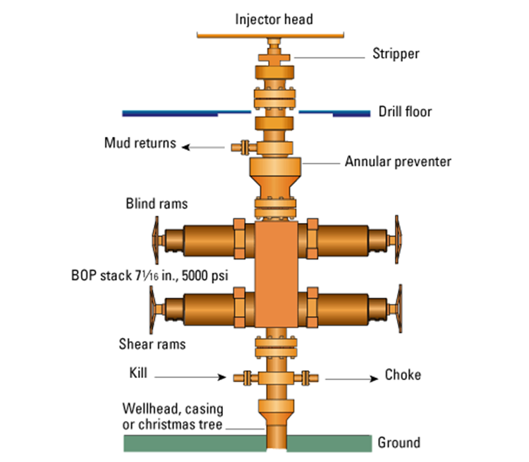
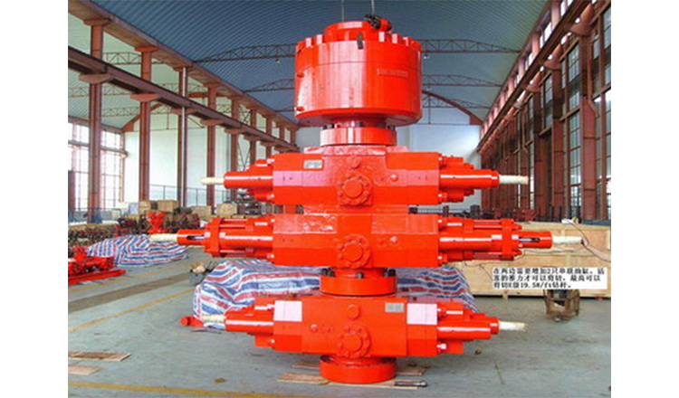
The blowout preventer is a large system of valves each of which is capable of isolating the subsurface of the well from the rig to provide control over the well. These valves are typically stacked as shown in the Figure 9.11 and sit below the rig floor on land wells or some offshore wells; or they may sit on the seabed on other offshore wells.
Figure 9.12 shows three type of valves (there are others) – an Annular Preventer, Blind Rams, and Shear Rams. The Annular preventer is the ring-shaped piece of equipment on the top of the BOP in Figure 9.11. As the name implies, the annular preventer is used to prevent flow through the annular space between the drill string or casing and the annular preventer. The annular preventer can also be used for non-cylindrical pipe, such as the kelly, or open hole. The annular preventer consists of a doughnut shaped bladder that when in the open position allows the drill pipe to rotate but in the closed position seals the annulus. Figure 9.13 provides a schematic of the annular preventer.
In Figure 9.13, the blue area represents the doughnut-shaped bladder. As mentioned earlier, in the open position, (A), the drill pipe can be rotated or can be run up or down; while in the closed position, (B), the bladder pushes out, closing off the drill pipe, kelly, or open hole. The bladder based sealing element is not as effective as the ram type sealing elements; however, almost all blowout preventer stacks include at least one annular preventer.
In the first objective re-quoted above, if we can keep the pressure exerted by the drilling mud greater than the pore pressure, then we know that fluids will flow in the direction of the mud to the formation. This cannot always be achieved. For example, if we drill through a natural fracture or if our mud density is too great and we inadvertently fracture one formation, then we may lose large quantities of the drilling fluid into the fracture (Lost Circulation). In this situation, instead of having the full weight of the mud column exerting pressure on a second (porous and permeable) formation, we may only have a fraction of the oil column height exerting a lower pressure on that second formation.
improper mud replacement during tripping: while tripping out of the hole mud volumes must be pumped into the wellbore at high enough rates to replace drill pipe being removed from the wellbore;
lost circulation: as discussed earlier if large volumes of drilling fluid enter the subsurface in (1) high permeability formations, natural fractures, or drilling-induced fractures, then the effect is a shortened height and weight of the mud column.
increase in the rate of flow of the drilling fluid returns at constant pump rates (primary indicator of a kick):The increased rate is caused by formation fluids entering the wellbore and is a strong indication of a kick. In addition, if it is a gas kick, due to the compressible nature of gas, as the gas bubble travels up-hole and hydrostatic pressures decrease, the volume of the bubble will increase due to expansion.
volume of mud in the mud pit increases when no additional drilling fluids are added to the mud system (primary indicator of a kick):For the same reasons as mentioned above, if the volume of mud in the mud pits increases when no additional fluids have intentionally added, then the increased volume is caused by formation fluids entering the wellbore and is a strong indication of a kick.
drilling fluids returns continue to flow when the mud pumps are turned off (primary indicator of a kick):Drilling fluid returns when the mud pumps are shut-off indicate that formation fluids are entering the wellbore and displacing the mud.
improper wellbore fill-up/volume-balance on trips (primary indicator of a kick):If the drill pipe is removed from the wellbore, then the change in volume in the mud pits should equal the volume of the drill pipe removed from the hole. An improper volume balance is a strong indicator of a kick.
pump pressure decrease and pump stroke increase (secondary indicator of a kick):If low density fluids are displacing heavier drilling fluid in the annulus, then this will cause the pump pressure to decrease (the annular side of the u-tube is lighter than the drill pipe side of the u-tube which contains the mud pump pressure gauge). The imbalance in the u-tube, just described, will cause the heavier drilling fluid in the drill pipe to fall due to gravity, causing the mud pump to increase the number of strokes to keep up with the pressure imbalance.
occurrence of a Drill Break or Bit Drop (secondary indicator of a kick):A Drill Break (sudden change in the rate-of-penetration) or Bit Drop (sudden increase in the drill bit depth) typically occur at a change in the lithology of the formation being drilled. In particular, a large bit drop may be an indication of drilling through a natural facture system. Both drill breaks and bit drops are normally recorded in the drilling records. When working on naturally fracture reservoirs, these drilling records may be useful for mapping natural fractures. I personally worked in a field where we had a 12 meter (~ 36 ft) bit drop in one well in the reservoir – think about it, you are drilling away at a certain rate-of-penetration and, all of a sudden, the bit drops 36 feet for no apparent reason. This was caused by drilling through a solution enhanced fracture which over geologic time formed a cavern in the reservoir (this occurred several years prior to my arrival, but it was in the drilling records).
reduction in the mud weight (secondary indicator of a kick):The Mud Man may observe a reduction or Cut in the mud density at the rig-site mud laboratory. This again may be an indication of a kick.
When a kick occurs, the Operating Company and Drilling Company always have well-specific plans in-place for all wells to ensure that any controllable kick does not turn into an uncontrollable blowout. I cannot go into the details of a well-specific procedures, but they will include some of the following features if a kick occurs during drilling operations:
Pick the drill bit off-bottom and Space Out (Spacing out refers to pulling the drill pipe out the hole so that the top connection – the thickest part of the drill string containing the threads and joints – is several feet above the rig floor. Spacing out ensures that the smaller diameter section of the drill string is inside the BOP, so that pipe rams can close and seat properly or blind rams or shear rams are opposite the smallest diameter section of steel. See Figure 9.15B)
Other procedures will be used if the kick occurs while tripping into or out of the well. The details of some aspects of this procedure such as hard or soft shut-ins and the circulation methods, The Driller’s Method and The Weight and Wait Method, will be discussed in detail in your later drilling classes. More importantly, for every well that you are involved with, there will always be Daily Safety Meetings that discuss the current status of the well and the important safety aspects of all drilling activities related to that day’s operations.

Positive displacements pumps are generally used on drilling rigs to pump high pressure and high volume of drilling fluids throughout a drilling system. There are several reasons why the positive displacement mud pumps are used on the rigs.
The duplex pumps (Figure 1) have two cylinders with double acting. It means that pistons move back and take in drilling mud through open intake valve and other sides of the same pistons, the pistons push mud out through the discharge valves.
When the piston rod is moved forward, one of intake valves is lift to allow fluid to come in and one of the discharge valve is pushed up therefore the drilling mud is pumped out of the pump (Figure 2).
On the other hand, when the piston rod is moved backward drilling fluid is still pumped. The other intake and discharge valve will be opened (Figure 3).
The triplex pumps have three cylinders with single acting. The pistons are moved back and pull in drilling mud through open intake valves. When the pistons are moved forward and the drilling fluid is pushed out through open discharge valves.
When the piston rods are moved forward, the intake valves are in close position and the discharge valves are in open position allowing fluid to discharge (Figure 5).
On the contrary when the piston rods are moved backward, the intake valve are opened allowing drilling fluid coming into the pump (Figure 6). This video below shows how a triplex mud pump works.
Because each pump has power rating limit as 1600 hp, this will limit capability of pump. It means that you cannot pump at high rate and high pressure over what the pump can do. Use of a small liner will increase discharge pressure however the flow rate is reduces. Conversely, if a bigger liner is used to deliver more flow rate, maximum pump pressure will decrease.
As you can see, you can have 7500 psi with 4.5” liner but the maximum flow rate is only 297 GPM. If the biggest size of liner (7.25”) is used, the pump pressure is only 3200 psi.
Finally, we hope that this article would give you more understanding about the general idea of drilling mud pumps. Please feel free to add more comments.

If you ended up on this page doing normal allowed operations, please contact our support at support@mdpi.com. Please include what you were doing when this page came up and the Ray ID & Your IP found at the

Unauthorized attempts to upload information and/or change information on any portion of this site are strictly prohibited and are subject to prosecution under the Computer Fraud and Abuse Act of 1986 and the National Information Infrastructure Protection Act of 1996 (see Title 18 U.S.C. §§ 1001 and 1030).
To ensure our website performs well for all users, the SEC monitors the frequency of requests for SEC.gov content to ensure automated searches do not impact the ability of others to access SEC.gov content. We reserve the right to block IP addresses that submit excessive requests. Current guidelines limit users to a total of no more than 10 requests per second, regardless of the number of machines used to submit requests.

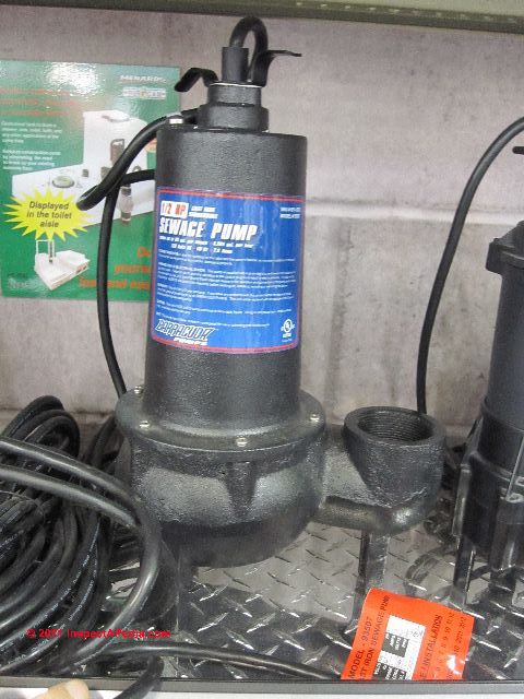
This article describes the causes of and steps to prevent clogging and/or damage to septic pumps, grinder pumps, and sewage ejector pumps. We include excerpts from sewage or septic grinder pump manufacturers" installation manuals that describe sewage pump diagnosis & repair procedures.
This article series also lists septic and grinder pump types, brands, and will identify pumps that are resistant to damage from debris or objects that may enter the toilet, sewer line, or septic tank.
InspectAPedia.com readers report troubles with several types of septic pumps, sewage pumps, and grinder pumps, both for sewage ejector pumps located in the home (such as to pump a basement toilet waste line up to a higher main drain) and for pumps that operate septic or graywater tanks.
Septic pump damage may occur from certain objects that enter building drains regardless of where and how the pump is used, including in-building sewage ejector pumps (shown at left) or pumps used in septic tanks or septic effluent tanks.
Some of the items in this list won"t damage the septic tank itself as their volume is small and they don"t usually block the septic piping or baffles, but if your septic system or even public sewer connection use a septic pump, grinder pump, or sewage ejector pump, the items listed here can clog and damage or even destroy a sewage pump, leading to costly repairs.
Watch out for the following conditions that cause clogging and even burn up of various types of sewage pumps, grinder pumps, ejector pumps, and septic pumps:
Cigarette butts are not biodegradable and should not be flushed into the septic system. And the filters on cigarette butts can clog and destroy septic pumps.
Condoms won"t clog a pipe but like some other debris, because they are of modest size and are quite flexible, but condoms are (usually) not bio degradable. So we listed condoms, or other latex products such as latex gloves above as "never flush".
A condom in the septic tank will probably join other debris in the tank"s floating scum layer, and will be removed at the next tank pump-out. Of course, if the septic tank outlet tee baffles are missing, the condom will join other floating debris on its way out to clog the drainfield, so ask your septic pumper to check the condition of the septic tank baffles when the septic tank is next pumped.
BUT if your system uses a septic pump or grinder pump or sewage ejector pump, this material can clog the pump impeller and cause expensive pump damage or motor burnout.
Cotton swabs (Q-tips®) have been known to clog a drain or two - cotton is not readily biodegradable, though cotton swabs are trivial in volume and are not important in the septic tank itself.
BUT if your system uses a septic pump or grinder pump or sewage ejector pump, this material can clog the pump impeller and cause expensive pump damage or motor burnout.
Disposable wipes - such as baby wipes or personal hygiene wipes, even products described as "biodegradable" or "OK for use in septic systems" may NOT be OK: if your system uses a septic pump or grinder pump or sewage ejector pump, this material can clog the pump impeller and cause expensive pump damage or motor burnout. S
The following Common Sewage / Septic Pump Problems and sewage pump (septic grinder pump) diagnosis & repair advice is adapted from installation manuals from manufacturers & from other sources.
Vent opening at check valve: Zoeller Pump provides a combined union/check valve, the "Unicheck". The company notes that with this valve is installed, the installer must drill a 3/16" (5mm) vent opening in the discharge line at a height even with the top of the pump.
Zoeller Pump Company, "Installation & Service Instructions, 803/805/807 Grinder Pumps", [PDF] Zoeller Pump Co., P.O. BOX 16347 • Louisville, KY 40256-0347, Website: Zoeller.com Retrieved 2016/04/05, original source: http://www.zoellerpumps.com/en-na/product/1242-#documents
Zoeller Pump Company, "Installation Instructions, Recommended Models, Effluent/Sump/DeWatering & Sewage[pumps]", [PDF] Zoeller Pump Co., P.O. BOX 16347 • Louisville, KY 40256-0347, Website: Zoeller.com Retrieved 2016/04/05, original source: http://www.deanbennett.com/53-install-inst.pdf
Nearly all authorities warn that acids or other chemicals might harm a septic system (I agree), and some chemicals may harm the seals in the grinder pump system as well.
However, a review of seven most-widely cited grinder pump and sewage pump advisory papers or instruction sets found that not one of them specified the actual level of acidity that would or would not be harmful to the pumping system.
That leaves us to make a reasonable guess at the answer: sufficiently diluted, an acid-based toilet cleaner should not harm either the pump or the septic system.
I pose that occasional use of a toilet stain remover (often including acids), used as directed, will be diluted enough to avoid such harm. You can reduce the risk of grinder or effluent pump damage further by additional dilution of the acid-based cleaner: try 2 or three additional flushes to dilute and then remove the acidic cleaner from the grinder pump reservoir.
Subsequent normal daily use of the sinks, showers, tubs, and toilets connected to the septic or sewage pump will further dilute any acidic content in the pump reservoir to a harmless level.
Watch out:flushing any acid into a residential sewage grinder pump or septic effluent pump that subsequently remains un-used for days, weeks, or longer, might risk damage to the pump components because in that case the acidic solution may remain in contact with pump parts for a prolonged interval.
At that level of usage and when further diluted by water as the toilet is flushed, even in the first flush the 6 oz. of solution (hazardous acidic) is diluted in 1-2 gallons of water or more (depending on toilet design and flush quantity).
In three flushes or 3 gallons total, you have diluted the original acidic CLR cleaner to 1% of its original strength. Even without knowing the actual level of acidity of the product as sold in the container, this is likely to be so dilute as to be harmless to the pump.
Emergency Overview: WARNING: EYE IRRITATANT. GHS Toxicity Category 2A Causes eye irritation and possible SKIN IRRITATANT GHS Category 3 – on sensitive skin.
which helps eliminate condensation and freezing. - GRINDER PUMP FAQS for CT [PDF] Groton Connecticut Department of Public Works, retrieved 20178/06/19, original source: http://www.groton-ct.gov/depts/pubwks/docs/Grinder%20Pump%20Website%20info%20the%20hurricane.pdf
Heather, sewage ejector pumps normally are operated by a float control switch. As wastewater rises in the holding tank when the level is high enough the float switch turns the pump on.
So if your sewage pump never turns off, presuming it"s properly wired, the float switch is either stuck on debris in the holding tank, or the switch needs to be replaced.
The green arrow in our sewer pump float switch example is the actual switch assembly that turns the motor on and off as the float, on its shaft, rises and falls vertically. Image source: plumbingsupply.com [4]
Take a look at the two most common sewage float switch types in our Little Giant™ sketch above and the Zoeller™ sewage pump and control switch image at left. Your switch probably looks like one of these two types.
In a few rare instances I have found homes at which the ejector pump float switch had failed and the owners, rather than replacing the switch, just hard-wired the pump to turn on and off by a manual switch.
This is a bad idea for obvious reasons including inconvenience and the risk that either the pump is left on longer than necessary or left off leading to a sewage backup.
Watch out: in addition to obvious bacterial hazards at sewage pumping stations there are methane gas hazards of explosion and asphyxiation - don"t work alone. Also see our list above of things that can clog up or damage a sewage ejector pump.
Is your sewage ejector pump already damaged? Maybe not. Some sewage pump models indicate in the installation and maintenance manual that the pump can tolerate being run "dry". But best practice is to set the float control switch so that the liquid level does not drop below the pump body.
The Little Giant™ remote float control switch (left) can be used as an auxiliary control / warning device on sewage and sump pump ejector installations to control an alarm.
By mounting this switch at an activation position higher than the normal float switch that controls pump operation, this remote control switch can activate a light or audible alarm to warn building occupants that the sewage system is not being emptied.
I don"t like the idea of these sewer ejection pumps as they suck electricity, i feel my builder dug the foundation too deep and therefore stuck me with this annoyance on my new home.
Dave you can figure out just how much electricity your ejector pump is using either by some careful examining of the electric meter itself or by looking up the specs on your motor.
Normally these motors run only intermittently. I"d be surprised if the ejector pump was using as much overall electricity in watt-hours as your refrigerator, freezer, or air conditioner.
The septic pump float switch at left describes a common sewage pump control method used on Little Giant™ and many other submersible sewage grinder pumps.
This type of sewage pump float switch, also used on lots of sump pumps, swings in an arc between its high and low positions. It"s a simple, reliable electric switch, but debris in the holding tank or improper tethering can lead to switch jamming.
Note that by moving the tether position of the float wire in the pumping chamber you can adjust the pump cut-in and cut-out wastewater levels in the holding tank. Sketch courtesy of plumbingsupply.com [4]
What do you suppose was the large white waxy clumpy substance that I found recently in my septic pump container? The sticky substance was stuck to the sides of the tank (where it was several inches thick).
It was also stuck all over the septic pump, and stuck all over the float switch - .which of course was the problem and the reason for opening the tank.
[Click to enlarge any image] Photo: white waxy deposit clogging the inlet of a sewage ejector pump - InspectApedia.com photo from an anonymous reader.
Eboigbodin (2008), and McBain (2003) as well as many other researchers cite the role of bacteria and fungi in the formation of biofilm slimy deposits in water supply and drain piping systems.
Common among the biofilm organisms are the fungus Fusarium sp. often detected in plumbing drains (Short 2011), Pseudomonas aeruginosa, other bacteria, as well as yeasts such as Rhodotorula mucilaginosa (usually red or orange) or Exophiala dermatidis (a black yeast) spread from dishwashers to kitchen. - Zupančič 2016
Bacterial growth clogging in a drain line, drain trap, or in an ejector pump or sewage pump can be aggravated by extra sources of bacteria such as bacteria forming in air conditioning condensage dispensed-of by dripping it through the condensate drain system into a seldom-used trap or sewage pump chamber.
A good guess is that your sewage ejector tank or septic tank that uses a septic pump was clogged by someone who used too much powdered detergents in a clothes washer or dishwasher.
It"s well established that using excessive amounts of powdered detergent in a dishwasher or clothes washer can lead to accumulation of a gooey mess that clogs drains or even septic drainfields. Some bar soaps can also form waxy clogs or blockages in plumbing systems and sewage or effluent pumps.
You have provided another important example: excessive detergent use OR using a budget detergent that contains large amounts of clay fillers can clog the pump float control switch or the pump intake in a sewage ejector pump or sewer pump as well.
Soaps produced using sodium hydroxide are referred to as "hard" soaps that are more-difficult to dissolve in water, while soaps produced using potassium hydroxide tend to be more-easily soluble and are thus called "soft" soaps.
Yep it"s true, some fools dump plaster or drywall dust and debris down toilets or other drains while cleaning up after a plastering or drywall installation or repair job.
Don"t do that. Both plaster and drywall dust will form a hard-to-remove drain blockage in nearby traps or drain lines. While acid-based drain cleaners might remove such blockages more-likely you"ll need to use a power snake or other mechanical drain cleaning system.
Other waxy clogging can be traced to soaps and detergents: this second common cause of waxy deposits that clog pumping chambers or piping are fats and oils that were flushed down drains.
For residential drains and pump suffering from fat or oil clogging waxy deposits, plumbing drain FOG (Fat Oil Grease) degreasers (such as Cloroben PT-4) may help dissolve the clog.
Some Hercules products such as Hercules PT-GIO1™ combine grease solvents and "waste digesting bacteria" while Hercules PT-4 (or Cloroben PT-4) is a formula designed to rapidly dissolve FOG (Fats Oils and Grease) using a non-acidic, non-caustic formula that is described as "safe on all types of piping materials when used as directed"
If your water is "hard" or high in calcium or magnesium that condition, combined with those types of soap particularly invites the formation of waxy white blobs that clog drains, traps, and septic pumps.
Her plumber cut-out and replaced the clogged trap as well as the most-clogged nearby PVC drain lines and physically removed wax deposits in the downstream drain opening.
You may need to replace the worn, corroded anode rod in your water heater and you may need to have your water tested and if it"s sufficiently alkaline, you may need to install a water treatment system.
Bédard, Emilie, Michèle Prévost, and Eric Déziel. "Pseudomonas aeruginosa in premise plumbing of large buildings." MicrobiologyOpen 5, no. 6 (2016): 937-956.
Eboigbodin, Kevin E., Allyson Seth, and Catherine A. Biggs. "A review of biofilms in domestic plumbing." Journal‐American Water Works Association 100, no. 10 (2008): 131-138.
However, drinking water should also meet the necessary quality requirements at the point of consumption even though domestic plumbing systems are usually not constructed from the same materials that are used to construct distribution systems.
Fleming, I. R., and R. K. Rowe. "Laboratory studies of clogging of landfill leachate collection and drainage systems." Canadian Geotechnical Journal 41, no. 1 (2004): 134-153.
McBain, Andrew J., Robert G. Bartolo, Carl E. Catrenich, Duane Charbonneau, Ruth G. Ledder, Alexander H. Rickard, Sharon A. Symmons, and Peter Gilbert. "Microbial characterization of biofilms in domestic drains and the establishment of stable biofilm microcosms." Applied and Environmental Microbiology 69, no. 1 (2003): 177-185.
Drain biofilms harbored 9.8 to 11.3 log10 cells of viable enteric species and pseudomonads/g, while CDFF-grown biofilms harbored 10.6 to 11.4 log10 cells/g.
Since live-dead direct staining revealed various efficiencies of recovery by culture, samples were analyzed by DGGE, utilizing primers specific for the V2-V3 region of eubacterial 16S rDNA. These analyses showed that the major PCR amplicons from in situ material were represented in the microcosms and maintained there over extended periods.
Sequencing of amplicons resolved by DGGE revealed that the biofilms were dominated by a small number of genera, which were also isolated by culture. One drain sample harbored the protozoan Colpoda maupasi, together with rhabtidid nematodes and bdelloid rotifers.
Zupančič, Jerneja, Monika Novak Babič, Polona Zalar, and Nina Gunde-Cimerman. "The black yeast Exophiala dermatitidis and other selected opportunistic human fungal pathogens spread from dishwashers to kitchens." [PDF] PLoS One 11, no. 2 (2016): e0148166. Retrieved 2018/07/04, original source: http://journals.plos.org/plosone/article?id=10.1371/journal.pone.0148166 Creative Commons Lic.
We investigated the diversity and distribution of fungi in nine different sites inside 30 residential dishwashers. In total, 503 fungal strains were isolated, which belong to 10 genera and 84 species. Irrespective of the sampled site, 83% of the dishwashers were positive for fungi.
Comparison of fungal contamination of kitchens without and with dishwashers revealed that virtually all were contaminated with fungi. In both cases, the most contaminated sites were the kitchen drain and the dish drying rack.
We have a Zoelner grinder lift pump that recently clogged with toilet paper when to wrapped around the impeller. Are there any recommendations for what type of TP is best to prevent these types of problems?
Thomas I"ve been testing toilet paper breakdown rates for almost a decade - one experiment is long-going; my OPINION is that all toilet papers break down just fine in a septic tank itself - changing the paper brand won"t reliably fix the problem you encountered.
So I suspect there"s a different problem: the grinder - tampons, or some other stuff can clog up sewage pumps. (Dental floss is one of the worst offenders and it"s hard to keep that out of the pump).
But Zoeller indicates quite clearly that their residential sewage grinder pumps, such as the Zoeller Shark 803/805/807 Residential Grinders can handle "all flushable wastes" - to me that means feces and toilet paper but not tampons and probably not dental floss.
Are we sure you have the right pump type and model installed. Sometimes people install a de-watering sump pump or a simple effluent lift pump where a grinder pump is needed.
Zoeller"s sewer pump instructions also point out that a role of the pump chamber cover is to prevent debris from entering the pumping chamber from that direction as well.
Watch out: at SEPTIC & SEWAGE PUMPS we explain that choosing the wrong type of pump, such as installing a simple basin pump or effluent pump (designed to handle primarily liquid waste) on a system where blackwater (toilet waste) is entering the system is likely to lead to pump clogging and failure.
I"m glad you recognize that all we have is an opinion since we"re not on site and there may be important details that we can"t see and don"t know about this problem.
I would be tempted to try to fish with a small hooked wire, working very carefully so it"s not to push the broken off brush tip further down the drain but to see if I could hook it and drag it back out.
I let water run in the tub several times and flushed toilet few times with pump working. Only option is to call sewer service contractor to inspect the sump pit while flushing to see any thing comes or look inside. Your expert opinion is much appreciated.
I have 3 year old Ashland Sewage pump model SW50 working well . I attempted to clean the tub drain which is connected to the sewage pump along with toilet. I was using Sink Wizard with specially hardened bristle tips, when it apparently got broken and bristle tip is gone, it is about 3/4" long.
Because there is no way to get access to p tap if any , will get in the sewer pump and give any problem?. Should I call plumber and sewer service to inspect the sewer tank to retrieve the piece or if it is stuck in the p tap, should I continue use the bath tube so that it will be flushed in to the sewer tank and pumped out without causing any damage to the pump?
I am puzzled too as I don"t know exactly how leaving the pump powered off for a time would cause a banging noise when it"s plugged back in. I would probably start by visual inspection including looking at how the pump is secured and looking for loose components
My grinder pump alarm went off yesterday and the light was red I went out and noticed that one of the plugs had been unplugged by a contractor working at my property I immediately plugged it back in and the light went off 10 seconds later but now I have a banging noise that"s coming from right underneath with a grinder is I have no idea what it is...
You need a grinder pump to move wastewater, including solids, out of your in-home pumping chamber out to your septic tank. That 50 gallon pumping station cannot work if all solids remained in such a small space. (Seems obvious; I"m not a sanitary engineer).
I have a septic mound system with a two compartment concrete 1000 gallon tank and my home is below the tank as the property is uphill. All the drains collect into a 50 gallon fiberglass holding tank in the basement and is ejected by a Weil brand single phase 1 hp 230v 1750 rpm grinder pump (yes, grinder pump) the run (I think called total dead head)including all horizontal and vertical distance is approx 60 feet .
My question is, was it appropriate for the builder to install a grinder pump when it seems grinder pump use is almost universally frowned upon in septic systems due to the slurry the grinder makes being difficult to separate into solids and liquid components that septics need to operate effectively without clogging the field.
Should I pull the grinder pump and install a comparably spec’d sewage ejector pump or is there certain situations that might require or benefit from the grinder pump. I can’t get a straight answer from anyone, please help with some advice if you can.
It might be if it"s the wrong pump for the application. For example if you need a grinder pump and you don"t have one with the capacity then it may be clogged and destroyed
I have been using sewage pump for lower portion of the property for 3 years. This pump generally takes care of regular use of one kitchen and bathroom. In the last year and a half, it started to have deposits coagulate at the bottom of the sewage pump and every 5 to 6 months, we have to clean it to avoid clogging. What could be the reason?
If the unfortunate event of a few non-flushable wipes going down the toilet drain has *already occurred*... will pumping the septic tank resolve the potential problems and remove the unwanted material?
I am sorry to have to offer what"s an annoying guess but I suspect that if toilet paper is accumulating at all in the sewage ejector pump basin then the wrong type of pump may be installed.
I live in a basement with a sumppump sending waste up to the sewer. Toilet paper hardens on the ball if I am gone for a few days. What can I use to keep waste soft and flowable
The number of companies selling septic additives and "cleaners" is nearly equal to the population of Indonesia; at SEPTIC TREATMENTS & CHEMICALS https://inspectapedia.com/septic/Septic_Tank_Treatments.php we describe some of these and explain that they are generally not needed for proper septic TANK maintenance.
However there may be reasons to clean the sewage ejector pump and pumping chamber. Narrowing the search to those products gives some suggestions such as Core Biologic"s Ejector Tank Treatment https://www.corebiologic.com/ejectortanktreatmenthh
We had our system alarm "go off" about a week ago on our detached dwelling unit (with grinder pump) it turned off after about 3 minutes and after some testing it appears to be in working order. I did a light snaking off the drains and surprisingly a bunch of dental floss came up (disgusting and concerning all in one) along with some of the "grey matter" you wrote about above. So I am wondering if there is a product or substance that I can put down the drain periodically that will help keep the system "clean"?
If you"re referring to the aerator pump on an aerobic septic system most of those are designed to run continuously occasionally there"s some designs that use a timer. If you leave it off your system is going to a backup or you"ll damage the drain field.
You can remove some grease type sludges with non-caustic treatments such as the Clorben PT product series. I"d check for a sticking control float that is not switching the pump on when it should.
A yellow sludge builds up on the float and won"t let it ride up to make the switch located on top of cover come on. I have to take out one of the infeed pipes and blasg it off with hot water from our water heater. It"s located in the basement and puts out an odor. I"d like to know what I could treat it with to dissolve this sludge without damaging the pump.
I have a cajun air septic system and the high water alarm is on and the pump is running but not pumping and i looked inside and the water inside the tank isn"t high enough to pump water
the pump impeller may be damaged or partly clogged. Sometimes a clog will separate itself when power is off, the pump can run for a time, then the clog is drawn back.
Over the summer we noticed an odor outside, opened the cover of the pit to see the water/sewage level almost to the top of the pit about 3 feet deep. The pump was running but not ejecting the sewage.
The pump worked fine and ejected the wast and shut off. Have been keeping and eye on it and now almost daily the container is full, pump is running but not ejecting and I simply unplug it, lift pump couple times and plug it back in, it ejects until pit empty and turns off like it should, however next day it is the same thing, full and running but not ejecting.
No question that tampons and the like can clog ejector and sewage pumps. Besides posting "Don"t flush" signs, which are never 100% effective, one might need to install a pump whose manufacturer says can handle those obstructions. Screens clog.
We have a small business with several toilets and sinks. Our sewer line runs to a jointly owned pump vault (our sewage and our neighbor"s). We have a dual-pump (ejector) system in the vault that pushes the sewage up and down a pressure line (down a side street) to the City"s main in a major cross street.
A new business took occupancy of the neighbor building a year ago (we"ve been here for more than 25 years), and over the past year we"ve had nothing but trouble with clogged pumps
Typically feminine products and other debris. If this were solely the neighbor"s problem, we"d let them suffer through it, but they"ve made it our problem. Do you have any suggestions of a macerator/grinder that we could place in-line and up-stream from the pumps? And/or is there another solution you would recommend? All suggestions appreciated. Thanks
The pump shut off last night so I just did a load of laundry now it looks like the pump isn"t working at all as the downstairs toilet bowl is complete full. We still cannot figure out how to get the lid off this thing and my husband knows a lot about plumbing but not this sewage pump.
So we are still wondering how to get the lid off this thing. It look similar to the hand drawn picture above which says Basic Environment One Grinder pump.
Continue reading at SEPTIC PUMP INSPECTION & MAINTENANCE or select a topic from the closely-related articles below, or see the complete ARTICLE INDEX.
SEWAGE PUMP DAMAGE & REPAIR at InspectApedia.com - online encyclopedia of building & environmental inspection, testing, diagnosis, repair, & problem prevention advice.

Wellbore instability is a frequent problem of shale drilling. Accurate calculation of surge-swab pressures in tripping processes is essential for wellbore pressure management to maintain wellbore stability. However, cutting plugs formed in shale horizontal wells have not been considered in previous surge-swab pressure models. In this paper, a surge-swab pressure model considering the effect of cutting plugs is established for both open pipe string and closed pipe string conditions; In this model, the osmotic pressure of a cutting plug is analyzed. The reduction of cutting plug porosity due to shale hydration expansion and dispersion is considered, ultimately resulting in an impermeable cutting plug. A case study is conducted to analyze swab pressures in a tripping out process. The results show that, in a closed pipe condition, the cutting plug significantly increases the swab pressures below it, which increase with the decrease of cutting plug porosity and the increase of cutting plug length. Under the give condition, the swab pressure at the bottom of the well increases from 3.60 MPa to 8.82 MPa due to the cutting plug, increasing by 244.9%. In an open pipe string condition, the cutting plug affects the flow rate in the pipes and the annulus, resulting in a higher swab pressure above the cutting plug compared to a no-cutting plug annulus. The difference increases with the decrease of the porosity and the increase of the length and the measured depth of the cutting plug. Consequently, the extra surge-swab pressures caused by cutting plugs could result in wellbore pressures out of safety mud density window, whereas are ignored by previous models. The model proposes a more accurate wellbore pressure prediction and guarantees the wellbore stability in shale drilling.
As a fossil resource preserved in nanoscale pores in organic-rich shale, shale oil is now an essential part of the world energy market [1]. In 2018, the production of shale oil was in the U.S., accounting for 64.7% of the total petroleum output [2]. In 2040, the productivity is estimated as . In China, the technically recoverable shale oil is estimated as , making up 9.7% of the technically recoverable shale oil resource in the whole world [3], mainly distributed in Jilin, Daqing, and the northwest of China [4]. Due to the exhaustion of conventional oil and gas resources, shale oil has been considered as one of the most promising energy sources in the future [4]. However, along with the great prospect of shale oil, significant challenges still exist. The horizontal well drilling in a shale formation is the kernel technique to exploit shale oil. Due to the special trajectory of horizontal wells and the unique characteristics of shale formation, problems caused by wellbore instability are frequent in drilling engineering. Accidents like borehole collapse, loss of drilling fluid and pipe sticking result in vast nonproductive time, and tremendous economic losses.
Wellbore stability is the core of safe and efficient drilling. To guarantee wellbore stability in shale formations, the wellbore pressure should be kept in an allowable range (safety mud density window) during a drilling process [5]. In general, the upper limit of the allowable range is the formation fracture pressure. With the wellbore pressure higher than the formation fracture pressure, tensile failure occurs in the wellbore rock [6], and drilling fluid flows into the formation through these fractures. This harmful drilling fluid loss defined as lost circulation [7] entails various problems [8] like consumption of enormous drilling fluid, inefficient cutting transportation, and reservoir pollution. Especially for shale drilling, the fluid loss aggravates the hydration of shale formation, resulting in further wellbore instability problems. The lower limit of the allowable range is determined by the larger one between the formation collapse pressure and the formation pore pressure. With the wellbore pressure lower than the formation collapse pressure, shear failure forms in the borehole rock and wellbore collapse occurs [6]. Wellbore collapse results in drilling problems like pipe sticking and borehole expansion. With the wellbore pressure lower than the formation pore pressure, formation fluid flows into the wellbore due to the hydraulic imbalance, defined as fluid influx. The fluid influx might induce serious drilling problems like well kick and blowout. Accidents caused by unsuccessful wellbore pressure management have resulted in enormous financial loss, nonproductive time, and even casualties [8, 9].
Most of the wellbore instability problems occur in tripping in/out processes, due to surge-swab pressures caused by pipe string movements. By definition, surge-swab pressures are the additional pressures generated by axial movements of the drilling string in the wellbore [10]. The research of surge-swab pressures has been started at an early time. Cannon [11] conducted tests to measure pressure changes with downhole pressure gauges when withdrawing pipes, regarding that the pipe withdrawing entails wellbore pressure reduction and might lead to blow-out accidents. Later, more experiments were conducted, and field data was investigated about surge-swab pressures [12–16], mostly for validation and improvement of theoretical models. Besides experimental work, theoretical studies are dedicated to establishing models of the surge-swab pressure, including steady-state models and dynamic (or transient) models. Clark [17] proposed semiempirical formulas of equivalent velocities for steady-state surge-swab pressure calculation. The pressure caused by fluid acceleration was also considered in his work. Burkhardt [18] established a surge-swab pressure model with theoretical studies, proposing the graph of mud clinging constant for convenient use. Fontenot and Clark [19] established a comprehensive steady surge-swab pressure model considering the drilling fluid property variation with depth. Subsequent work on steady-state surge-swab pressure has been dedicated to improving the model with various optimizations. Wang and Liu [20] established the steady-state surge-swab pressure model for Robertson-Stiff fluid, which is also a kind of yield-pseudoplastic fluid. In the work of Wang et al. [21], the effect of pipe eccentricity was considered on Newtonian drilling fluid. Crespo et al. [22] established a steady-state model taking account of fluid and formation compressibility and pipe elasticity for yield power-law (YPL) fluid. Later in 2013, a laboratory experiment was conducted, and a regression model of surge-swab pressures was developed for YPL fluid [23]. Tang et al. [24] established a steady-state model considering the effect of the drilling string velocity on the boundary condition. Ettehadi and Altun [25] established a steady-state model for Hershel-Bulkley (HB) fluid and applied in situ thermal rheological measurements to amend rheological parameters of drilling fluid. Krishna et al. [26] proposed explicit flow velocity equations for steady-state surge-swab pressure models of yield power law fluid to achieve more convenient calculation. The dynamic model (or transient model) is another route to deal with the issue of the surge-swab pressure [27–31]. Different from steady-state models, dynamic models take account of the elasticity of the pipes and the wellbore, the inertia and compressibility of drilling fluid, and the variation of tripping velocity [10]. Due to complexity of calculation, dynamic models are difficult to be applied in field drilling practice.
As noted above, scores of researches have been conducted on the surge-swab pressure in drilling engineering. However, in shale formation drilling, the effect of an influential phenomenon on the surge-swab pressure has not been considered in existing studies: the effect of a cutting plug. Due to the low permeability of the reservoirs, horizontal wells are essential in the development of shale oil. Wellbore uncleanness is a prominent problem of horizontal well drilling. Cutting particles are easy to accumulate in a horizontal wellbore, and cutting plugs might be formed when pump is stopped and tripping processes are conducted. Different from a cutting bed, a cutting plug fills the annulus at a certain length [32]. Fluid flow in tripping in and tripping out processes is affected by this particular accumulation of cutting particles. Excessive wellbore pressures under a cutting plug condition are not able to be predicted by previous models, resulting in the wellbore instability risk of shale drilling. In this article, a surge-swab model considering the effect of a cutting plug is established for both open pipe string and closed pipe string conditions. The porosity variety of the shale cutting plug is also considered. Finally, a case study is conducted to give a deeper insight.
The cutting plug is a cutting particle cylinder in the annulus between the drilling string and the wellbore formed in three conditions (Figure 1): (1) the cuttings accumulated at a borehole-enlarged section slide down due to the disturbance of the tripping pipe string, (2) the cuttings in the vertical and small-inclination sections settle down and accumulate in the large-inclination and horizontal sections when circulation is stopped, and (3) the cuttings at the lower side of the wellbore as a cutting bed are pushed and accumulated by the large diameter tools in repetitive reaming or tripping processes like the bulldozer work.
To develop the model, following assumptions are made: (1) the drilling fluid is incompressible, (2) for the accurate description of drilling fluid rheological properties and the simplicity of expression [33], power-law flow pattern is considered for the drilling fluid, (3) the rheology of the drilling fluid is assumed constant, ignoring the effect of temperature and pressure, (4) the drilling string and the wellbore are rigid, (5) the drilling string is concentric in the wellbore, and (6) the effect of cutting particles out of the cutting plug is overlooked.
Two types of cutting plugs are considered in the model, namely, the porous cutting plug and the impermeable cutting plug. The porous cutting plug refers to an accumulated permeable cutting bulk (Figure 2), allowing the drilling fluid flow in the form of seepage. Further, due to the hydration expansion and dispersion of shale cutting particles, the pores in the cutting plug shrink and are blocked by fine dispersive particles. The porosity of the cutting plug reduced and finally an impermeable cutting plug is formed. Therefore, the impermeable cutting plug refers to an impermeable cutting bulk (Figure 3).
The second part of the surge-swab pressure results from the osmotic pressure loss at the porous cutting plug, obtained with the flow rate through it and its physical properties like the porosity and the cutting plug length (in the flow direction). For the power law fluid, the osmotic pressure can be derived from the superficial velocity [34, 35] through a porous material:
The condition with both an impermeable cutting plug and a closed pipe string is the most dangerous for wellbore stability. Shown as the area surrounded by red dotted lines in Figure 3, the impermeable cutting plug, the wellbore, and the closed pipe string form an enclosed space. Without mass transfer between the enclosed space and its outside, the surge-swab pressure is not controlled by the frictional pressure loss and osmotic pressure loss. Considering the assumed incompressibility of the drilling fluid, the additional axial force on the closed bottom of the pipe string in tripping in or tripping out processes is directedly balanced by the additional hydraulic pressure in the enclosed space:
An open pipe string allows drilling fluid to flow between the annulus and the pipes during tripping processes through the access at the end of it, such as nozzles of the bit. Both the porous cutting plug and the impermeable cutting plug are considered with the open pipe string.3.3.1. Porous Cutting Plug
With the porous cutting plug in the annulus, the drilling fluid is still allowed to flow (Figure 4). Therefore, the surge-swab pressure above and below the cutting plug are composed the same as those under the closed pipe string condition, while the flow rates and velocities required for calculation are different due to the mass exchange with the inside of pipes.
Therefore, the surge-swab pressure in the annulus can be calculated. Similar to the closed pipe string condition, the wellbore pressure at any given position is obtained:3.3.2. Impermeable Cutting Plug
A horizontal well [39–41] is adopted to conduct a case study, consisting of a vertical section, a build-up section, and a horizontal section. The trajectory data and the input data of model calculation are separately presented in Tables 1 and 2. The length of the horizontal section is assumed as 1500 m. The casing shoe of the intermediate casing is assumed at the end of the build-up section (2394.3 m) for simplification. The case study is conducted for the swab pressure, while the surge pressure is exactly of the same magnitude with an opposite sign. The swab pressures are all calculated with the bit at the bottom of the wellbore (3894.3 m). The length of the cutting plug is only considered in the calculation of the osmotic pressure loss and ignored in the calculation of the wellbore pressure distribution.
For a closed pipe string, the swab pressure distributions in tripping out processes with and without a cutting plug are compared in Figure 6, along with the effect of the cutting plug length. The swab pressures are calculated with of the length of 1 to 5 m, respectively. Results show that, under the given condition, the swab pressures above the measured depth of the cutting plug (2500 m) are correspondingly identical, while below the cutting plugs, the swab pressures are all greater than those in a wellbore without a cutting plug. The swab pressures below the cutting plug increase with the increase of the cutting plug length, due to the greater osmotic pressure loss caused by a longer cutting plug. At the bottom of the wellbore, the swab pressure is 8.82 MPa with a 5 m cutting plug, increasing by 244.9% of the swab pressure without a cutting plug (3.60 MPa).
The effect of the porosity of the cutting plug on swab pressures is investigated and shown in Figure 7. The swab pressures are calculated with 0.24, 0.3, 0.36, 0.42, and 0.48 porosity, respectively. Similar with the trend of different cutting plug length, the results show that a lower porosity leads to a greater osmotic pressure loss, resulting in greater swab pressures below the measured depth of the cutting plug. At the bottom of the wellbore, the swab pressure is 7.18 MPa with a 0.24 porosity, increasing by 199.0% of the swab pressure without a cutting plug.
Consequently, the wellbore pressures differ among the cutting plug conditions above. The effect of the cutting plug length on the wellbore pressures is shown in Figure 8. The wellbore pressures above the measured depth of the cutting plug (2500 m) are correspondingly identical. Those below the cutting plug decrease with the increase of the cutting plug length, due to the greater swab pressures. At the bottom of the well, the hydrostatic pressure is 32.86 MPa, the wellbore pressure without a cutting plug is 29.25 MPa, and the wellbore pressure with a 5 m cutting plug is 24.03 MPa, 5.22 MPa lower than that in the condition without a cutting plug. The effect of the porosity on the wellbore pressures is shown in Figure 9. The wellbore pressures below the cutting plug decrease with the decrease of the cutting plug porosity. At the bottom of the well, the wellbore pressure with a cutting plug featuring a porosity 0.24 is 25.68 MPa, 3.57 MPa lower than that in the condition without a cutting plug.
The effect of the cutting plug length on the wellbore pressures is shown in Figure 12. Resulting from the swab pressure distribution, compared to the condition without a cutting plug, the wellbore pressures above the cutting plug are lower, and those below the cutting plug are higher. The wellbore pressure is 31.80 MPa at 2500 m for the no-cutting-plug wellbore, while it is 31.75 MPa above the 5 m cutting plug at the same measured depth. The wellbore pressure is 31.79 MPa at 2520 m for the no-cutting-plug wellbore, while it is 31.88 MPa below the 5 m cutting plug at the same measured depth.
The effect of the cutting plug porosity on the wellbore pressures has a similar trend with the cutting plug length, shown in Figure 13. The cutting plug with lower porosity results in greater differences of wellbore pressures from those without a cutting plug. Therefore, the impermeable cutting plug has the greatest influence. In the terms of quantity, the wellbore pressure at 2500 m above the impermeable cutting plug is 31.71 MPa and is 31.93 MPa at 2520 m below it.
The effect of the position of the cutting plug on the swab pressures is investigated. Swab pressures with an impermeable cutting plug at 2500 m, 2800 m, 3100 m, 3400 m, and 3700 m are calculated, shown in Figure 14. Besides the aforementioned results, the swab pressure difference varies with the cutting plug position. The difference between of swab pressures above the cutting plug between the conditions with and without a cutting plug increases with the cutting plug measured depth, which means the error of the previous swab pressure model applied on a cutting-plug condition is greater. In the terms of quantity, the swab pressure above the 2500 m cutting plug is 1.14 MPa and is 1.05 MPa without a cutting plug, resulting in a difference of 0.09 MPa, while the swab pressure above the 3700 m cutting plug is 1.80 MPa and is 1.65 MPa without a cutting plug, resulting in a difference of 0.15 MPa. Correspondingly, the difference of wellbore pressures above the cutting plug increases with the measured depth of it, shown in Figure 15. Consequently, the wellbore instability risk of application of the previous swab pressure model in a cutting plug condition is higher with a deeper cutting plug.
(1)A surge-swab pressure model is established considering the effect of cutting plugs, which is not considered in existing surge-swab pressure models. Both the open pipe string and closed pipe string conditions are considered. Cutting plug might develop from a porous one into an impermeable one due to clay hydration and dispersion of shale, resulting in the difference of pressure calculation(2)A cutting plug in the closed pipe string condition has significant influence on surge-swab pressures. The surge-swab pressures above the cutting plug measured depth are identical to those without a cutting plug, while the surge-swab pressures below increase with the increase of the cutting plug length and the decrease of the cutting plug porosity. Quantitively, at the bottom of the wellbore, the swab pressure is 8.82 MPa with a 5 m cutting plug () and 7.18 MPa with a 0.24 porosity (), respectively, 244.9% and 199.0% of the swab pressure without a cutting plug (3.60 MPa). Consequently, the previous model overestimates the wellbore pressure for 5.22 MPa with a 5 m cutting plug and for 3.57 MPa with a 0.24 porosity cutting plug, resulting in the risk of inappropriate wellbore pressure management(3)A cutting plug in the open pipe condition brings in more complicated influence on surge-swab pressures. Compared to the condition without a cutting plug, the surge-swab pressures are higher above the cutting plug measured depth and lower below. The difference increases with the decrease of the cutting plug porosity and the distance from the cutting plug and the increase of the length of the cutting plug. The difference above the cutting plug increases with the measured depth of the cutting plug. Quantitively, at the measured depth of 2500 m, the swab pressure of the no-cutting-plug condition is 1.05 MPa, while it is 1.11 MPa of the 5 m cutting plug condition and 1.14 MPa of the impermeable cutting plug condition. Compared to the cutting plug at 2500 m, the swab pressure above the 3700 m impermeable cutting plug is 1.80 MPa and is 1.65 MPa of the no-cutting-plug condition(4)The model proposed in this work reveals extra surge-swab pressures and hazardous wellbore pressures under the effect of cutting plugs ignored by previous models, detecting potential wellbore instability risk of previous models. The model can be applied in field practice to guide the optimization of tripping parameters and guarantee the wellbore stability of shale drilling
The calculation procedure for all four cases of the model in Section 3 (establishment of model) is systematized for the convenience of readers and users. Relevent references are denoted in Section 3.
The authors gratefully acknowledge the support of the National Natural Science Foundation of China (U19B6003; 51734010) and the Strategic Cooperation Technology Projects of CNPC and CUPB (ZLZX2020-01).
In the petroleum industry the more knowledge we gain the more progress is made. The ability to control the downhole environment while drilling has been a dream held by drilling and reservoir engineers for decades. In the past resent years, drilling engineers focused on preventing influx of formation fluid or gas, and weighted-up their mud accordingly, but as a result, drillers found themselves indeed between the rock and a hard place.
In the early 1970s a better knowledge of drilling hydraulics started being developed. Up to this point, hydrostatic pressure and formation temperature were derived by measuring static mud weight and viscosity at the surface and calculating a pressure gradient which could be extrapolated to bit depth. Formation temperature was also calculated from a gradient. Neither parameter was precisely known. In addition, every time the mud pumps were stopped to make a connection a pressure surge was initiated when the pumps were re-started. In a formation with a tight drilling margin, this pressure spike could break down a weak spot and cause loss of circulation. Contrarily, when the drill pipe was pulled to make a bit trip or even a short trip, care had to be taken not to swab-in the well.
Drilling decisions focused on extending bit life to the maximum rather than maximizing ROP. This was accomplished by using less-aggressive bits to mitigate vibration which is the leading cause of bit wear. Float valves were installed just above the drill bit to prevent the loss of drilling fluid and to force the seawater mixture and cuttings coming down the annulus to enter the fractures. Thanks to the knowledge acquire through the years new technology has risen. Cutting-edge techniques, sustained by innovative technology, are increasing the industry"s ability to safely and efficiently drill unstable formations in deepwater.

Suggested Citation:"3 Blowout Preventer System." National Academy of Engineering and National Research Council. 2012. Macondo Well Deepwater Horizon Blowout: Lessons for Improving Offshore Drilling Safety. Washington, DC: The National Academies Press. doi: 10.17226/13273.
The BOP system for Deepwater Horizon was a massive, 57-foot-tall, approximately 400-ton well control system located at the wellhead (DNV 2011a, I, 15). A riser pipe attached to the top of the BOP system extended to the


 8613371530291