
mud pump bonded valve free sample

Full-Open Valves . . . . . . . . . . . . . . . . . . . . . . . . . . . . . . . . . . . . . . . . . . . . . . . . . . . . . . . . . . . . . . . . . . . . . . 3
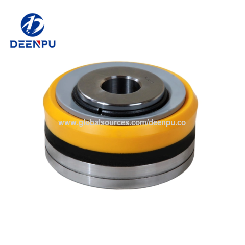
Bonded-Nitrile Pistons . . . . . . . . . . . . . . . . . . . . . . . . . . . . . . . . . . . . . . . . . . . . . . . . . . . . . . . . . . . . . . . . . 9
Mud-Pump Gear Sets . . . . . . . . . . . . . . . . . . . . . . . . . . . . . . . . . . . . . . . . . . . . . . . . . . . . . . . . . . . . . . . . . 13

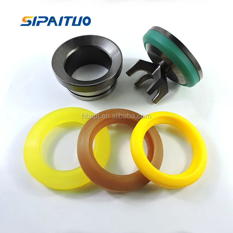
Customers said they wanted long-lasting, easy-to-use valves and seats, and we delivered. Made from domestically sourced steel, GD Energy Products valves feature a two-piece friction-welded design, proprietary bonded inserts, and innovative geometry to deliver significantly longer life. GD Energy Products’ field proven Valves & Seats meet API Standard, and come with our “Ready Inventory” promise that we’ll have it in stock, when you need it.
Our full-open valves and seats are designed for use in GD Energy Products PZ, F-Series, and National 12P lines of triplex drilling pumps. This gives you options to use these parts across your whole fleet of pumps.
A wide variety of mud pumps f 1600 options are available to you, such as 1 year, not available and 2 years.You can also choose from new, used mud pumps f 1600,As well as from energy & mining, construction works , and machinery repair shops. and whether mud pumps f 1600 is 1.5 years, 6 months, or unavailable.
The present invention relates generally to valves used in pumps handling abrasive fluids. More specifically, the present invention provides an improved valve seat which significantly reduces the impact stress on valves and seat assemblies during the pumping operation, resulting in reduced wear on the valve assembly and improved reliability for the pumping system.
Pumping systems which are used to pump drilling mud and other abrasive fluids generally incorporate positive displacement pistons or plungers which operate in a reciprocating manner in individual cylinders. Each piston or plunger cylinder has a suction and discharge valve and valve seat operating alternatingly and independently to control flow into and out of each cylinder. The valve typically comprises a disc-shaped body portion which includes an elastomeric valve insert which serves to seal the valve when in the closed position and also serves to cushion the impact of the valve body in the valve seat. A lower conical seating surface of the valve body also makes contact with the valve seat when the valve is in the closed position.
Because of high pump pressures (between 2000 and 5000 psi) and the abrasive solid particles suspended in the drilling mud, valves and valve seats wear at a rapid rate and must be replaced frequently. One of the most significant points of impact stress in the valve assembly is the point of contact of the lower conical portion of the valve body and the valve seat when the valve is in the closed position. The extremely high differential pressures in the valve cause the conical portion of the valve body to engage the valve seat with a very high impact. The repetitive impact eventually causes the faces of the valve body and the valve seat to become worn and pitted. There is a need for an improved valve seat which reduces the impact stress related to the impact of the valve body with the valve seat.
The apparatus of the present invention overcomes the difficulties of the prior art by providing an improved valve seat which significantly decreases the impact stress caused by the impact of a mud pump valve body against the valve seat. The valve seat comprises a generally cylindrical body portion with a sealing surface which is sloped from the outer surface of the cylindrical body portion toward an interior throat of said cylindrical body portion. The valve body comprises a generally disc-shaped portion and a truncated contical portion. An elastomer insert is received in a groove in the valve body. The conical portion of the valve comprises a sloped face, including a metal portion and an elastomeric portion formed by the elastomeric insert. In the valve seat of the present invention, an annular pressure relief groove in the cylindrical body portion of the valve seat allows the sloped face of the valve seat to flex thereby relieving a significant amount of the impact load between the opposing faces of the valve assembly.
FIG. 2a is a cross-sectional view of the valve assembly of FIG. 1, showing the valve received in the valve seat with the valve in the closed position, just prior to maximum impact of the valve body against the valve seat.
FIG. 2b is cross-sectional view of the valve assembly of FIG. 1, showing the valve received in the valve seat with the valve in the closed position just after maximum impact of the valve body against the valve seat.
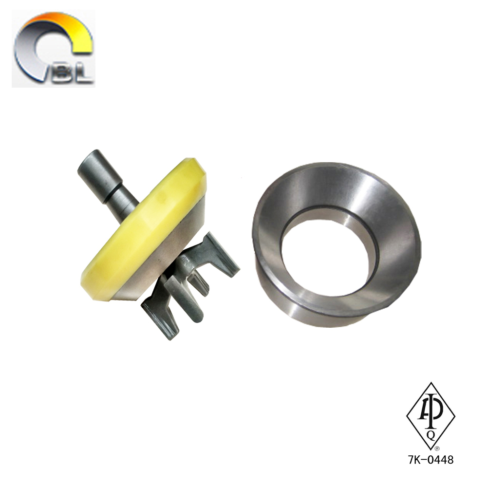
FIG. 1 is a perspective view of a mud pump valve assembly 10 comprising the improved valve seat of the present invention. The valve assembly shown in FIG. 1 is in the full open position. The valve assembly 10 is broadly comprised of a valve body 12 and a valve seat 14. The valve body comprises an upper valve guide 16 which maintains proper registration of the valve body within the pump housing. A plurality of valve guide feet 18 serve to maintain proper alignment of the valve with respect to the valve seat 14. The valve body comprises a generally disc-shaped portion 20 which is formed of metal, such as steel which has been heat treated by a carburizing process. The outer portion of the disc-shaped body has a generally C-shaped cross-section with an annular groove being defined by the interior of the C-shaped portion. A polyurethane or rubber insert is received in this groove. The insert serves to provide a partial damping of the impact of the valve body against the valve seat. However, this impact in most prior art systems is still high enough to cause significant wear on the operating faces of the valve body and the valve seat.
The lower portion of the valve body has a somewhat conical cross-section with a sloped surface illustrated by reference numeral 24. The sloped surface 24 comprises a rubber portion illustrated by reference numeral 26 and a metal portion illustrated by reference numeral 28. The valve seat 14 comprises a seating surface 30 with a portion 32 which engages the rubber portion 26 of the valve body surface and a portion 34 which engages the metal portion 28 of the valve body surface. FIG. 2a is a cross-sectional view of the valve assembly of FIG. 1, showing the valve received in the valve seat with the valve in the closed position, just prior to maximum impact of the valve body against the valve seat. FIG. 2b shows the valve received in the valve seat with the valve in the full closed position, with maximum impact of the valve body against the valve seat. Typically, the elastomer portion of the valve seating surface will make initial contact with the seating face of the valve seat. This is illustrated in FIG. 2a by the contact of the sloped face 26 of the elastomer insert 22 against the portion 32 of the sloped metal face of the valve seat. Note that the metal portion 28 of the sloped face of the valve body is not yet in contact with the portion 34 of the sloped face of the valve seat. The extremely high differential pressure on opposite sides of the valve, however, causes the elastomer insert 22 to compress rapidly to the position illustrated by the compressed elastomer insert 22 shown in FIG. 2b. The rapid compression of the elastomer insert results in an extremely high impact of the metal portion 28 of the valve face with the portion 34 of the valve seat face. In prior art valve seats this results in rapid wear of the metal portion 28 of the valve body and the portion 34 of the valve seat face. In the valve seat of the present invention, however, an annular pressure relief groove 36 allows the sloped face of the valve seat to flex thereby relieving a significant amount of the impact load between the opposing faces of the valve assembly.
Details relating to the valve seat 14 can be seen by referring to the cross-sectional illustration of FIG. 3. The outer surface of the valve seat comprises a valve seat shoulder 38 and a sidewall 40 having a conical taper. The slope of the sidewall 40 allows the valve seat to be received in a standard pump deck portion of a valve pot. The valve seat throat 42, defined by the internal cylindrical sidewall 44, transports the fluid passed through the valve assembly.
FIG. 4 is an enlarged view of a portion of the valve seat of the present invention showing details relating to the annular pressure relief groove 36. The relief groove is defined by vertical sidewalls 46 and 48 and an arch connecting the upper portions of the sidewalls 46 and 48. The arch is defined by two 90 degree segments with the inside segment having a radius which is two times as large as the radius of the outside 90 degree segment. The tangent point, illustrated by the reference numeral 50 is a point of smooth transition between the radii of the inside and the outside radii of the arch. The inside portion of the arch having the increased radius corresponds to the portion of the valve seat face which bears the impact of the metal portion of the valve body. Thus the impact load transmitted from the seating surface is dispersed over the larger radius inside the relief groove. This configuration maximizes flexure of the seating surface while preventing a stress concentration that would result in catastrophic shear failure of the seat.
Wear in the seating surface is directly proportional to the impact stress on the seating surface area of the valve seat. Impact stress "σ," which is reduced by the increased flexibility of the design of the present invention, is calculated using the following formula:
Utilizing finite element stress analysis, the calculated values for σs are approximately equal for the seating surface of a seat designed by the prior art and for the seating surface of the present invention. For both designs, the value of "h" is fixed and equal, being determined by the valve body and insert design. Again by finite element calculations, "y," deflection, is increased by a factor of 2 for the present invention. Using these values, the above equation yields values for impact stress, "σ," that are reduced by approximately 30% by the present invention.
The elastomeric insert is also positively affected by the present invention. The elastomeric seal, which is usually made of rubber or polyurethane material does not wear in the manner that the metal valve body and valve seat wear, i.e., through material loss. Material loss of the elastomeric seal is small during normal pump operation. Instead, the constant cyclical compression of the seal results in hysterisis in the seal that results in internal heat buildup and the eventual degradation of material strength to the point that the seal fails. As the metal valve and seat wear in the form of material loss from the impact stress, the amount of compression increases, hysterisis also increases to the point that material strength loss in the seal is accelerated and seal failure occurs after a shorter number of total cycles. Therefore, reduction in the wear rates of the metal valve body and valve seat also increases the life of the valve seal.
The flexible seat design of the present invention also improves pump operation because the valve opens faster and allows the pumped fluid to enter or leave the cylinder quicker. Because of the increased seat deflection, the seat stores energy that can be used to accelerate the valve to the open position before the piston or plunger begins the next stroke. In other words, the increased seat deflection acts like a recoiled spring which results in faster valve opening for smoother and more efficient pump operation.

FET manufactures a full range of valves and seats for every drilling and well-servicing application as part of our full line of Osprey® mud pump system solutions. All of our valves and seats can be used in water, water base, oil base and synthetic base mud applications. FET offers additional valves and seats not listed below, including drilling valves, frac valves and well service valves. FET’s QC standards for the dimensional and material specs are extremely rigid in comparison to other manufacturers. Contact your FET representative to learn more.
The 2,200-hp mud pump for offshore applications is a single-acting reciprocating triplex mud pump designed for high fluid flow rates, even at low operating speeds, and with a long stroke design. These features reduce the number of load reversals in critical components and increase the life of fluid end parts.
The pump’s critical components are strategically placed to make maintenance and inspection far easier and safer. The two-piece, quick-release piston rod lets you remove the piston without disturbing the liner, minimizing downtime when you’re replacing fluid parts.

TECHNICAL FIELD [0002] This invention relates to improved sealing and operational reliability of reciprocating gas compressor valves. More specifically, this invention is directed to the use of elastomeric material in connection with a sealing element of a reciprocating gas compressor valve to produce a reliable, durable seal.
[0003] Reciprocating gas compressors are equipped with valves that open and close to intake and expel gases. Often such valves alternate open and close with each revolution of the compressor crankshaft and there are a very large number of suction and discharge events per minute. As a consequence, the valve must be designed to tolerate a high level of repetitive stress. The sealing element of the valve establishes a seal between it and the opposing, fixed seating surface. Without proper sealing, hot discharged gas leaks back into the cylinder and temperatures escalate from recompression of the gas. Hence, the overall
[0004] While the valves in a reciprocating gas compressor are of various types and forms, each valve has a seating surface, a moving sealing element, a stop plate and mechanism to force the valve elements to close before the compressor piston reaches top or bottom dead center. The sealing element is pressed against the corresponding seating surface to close the valve by a combination of spring forces and differential pressures. The differential pressures are considerably larger in magnitude than the spring forces. An example of a typical reciprocating gas compressor valve is described in commonly assigned U.S. Pat. No. 5",511,583 to Bassett.
[0005] During the operation of the valve, the seating surface and the sealing element may be damaged by impact from liquids or solids entrained in the gas stream. Furthermore, operating conditions may vary in such a way that the sealing element strikes the seating surface at velocities higher than design tolerances of the sealing element or the seating surface, h other words, the forces generated cannot be tolerated by the sealing element. In such cases, the force of impact may cause fractures in the sealing element, accelerated wear in the sealing element and/or seating surface, and recession of the sealing areas of the sealing element. The recession phenomenon is particularly evident in sealing elements made of thermoplastic or metallic materials. Many traditional materials currently used do not have the ability to dissipate the energy resulting from high impact velocities, or entrained dirt and liquids and this may lead to premature failure of the ability of the reciprocating gas compressor valve to provide a gas tight seal.
[0006] When the sealing element or the seating surface is damaged and the ability to form a gas tight seal is lost, the valve or component elements must be replaced or refurbished. Additionally, in many cases such valve failures may be catastrophic in nature and result in damage to other parts of the reciprocating gas compressor or downstream equipment. Therefore, the longevity of the seal between the sealing element and the seating surface results in an increase in the useful life of the reciprocating gas compressor valve as measured by the mean time between failures of the reciprocating gas compressor valve. [0007] The sealing elements of reciprocating gas compressor valves have historically been made of metal. However, rigid thermoplastic materials were introduced in the early 1970"s. Both materials are used today. These stiff, non-elastomeric materials require a fine machine finish and are often lapped in order to further reduce surface defects. The contact surface of the seat may be flat or shaped in a manner that mimics the surface contours of the moving sealing element. [0008] When using a metal, thermoplastic material, or other rigid material as the sealing element, for the seal to be fully gas tight, the surfaces of the sealing element and particularly the sealing surface must be smooth and free from defects. In any machining operation, the cost and time required for manufacture are directly related and proportional to the surface finish required. Tighter tolerances require machine tools that are more precise and expensive. If there are defects in the sealing of a valve, gas will leak through the valve, component temperatures will elevate and the reciprocating gas compressor will operate in a highly inefficient manner. Furthermore, once the sealing integrity of the compressor valve
and dimensional changes even during storage. The changes are often severe enough to render the parts unusable. Metal parts can rust and pitting can occur that destroys the fine finishes. Parts that are mishandled or allowed to collide with other hard objects during shipment can make them unusable. This adds to the warranty loss of the supplier. [0013] There are an infinite number of operating conditions that exist. The variables include temperature, speed, impact or shock damage during opening and closing, pressure, gas constituents, and the amount of entrained dirt and or liquids in the gas. The service life of a valve is typically inversely proportional to the amount of debris (liquid or solid) in the gas stream. As particles strike the fine surfaces of the sealing element, damage to the valve degrades its ability to establish a gas tight seal. Recovery of the gas tight seal is not possible unless the sealing element of the valve is replaced or refurbished.
[0014] Due to disruptions in service conditions and due to the nature of the motion of the sealing elements during operation, the brittle metals and thermoplastics may suffer chipping of the edges. Chipped surfaces often lead to fractures and subsequent failure of the valve whereby the sealing elements fracture into one or more parts. Total replacement of the valve is then necessary.
[0015] A need exists, therefore, for a sealing element that efficiently seals a reciprocating gas compressor valve for the purpose of improving reliability and durability.
[0016] The present invention is a reciprocating gas compressor valve comprising a sealing element made of and having at least one layer of elastomeric material. The sealing
[0017] The novel use of elastomeric materials in reciprocating gas compressor valves provides the following benefits. First, the inherent property of elastomers to flex and conform to irregular or damaged surfaces produces a gas tight seal over a variety of damaged or undamaged surfaces. In short, the use of elastomers provides greater confidence that a gas tight seal is established even when the sealing surfaces are not smooth or in perfect condition. Second, the use of elastomeric material eliminates the process of lapping the sealing surfaces. Most valves and valve designs make use of lapping to create or restore sealing surfaces. Lapping produces the fine finishes necessary to establish a gas tight or near gas tight seal in the current state of the art. Surface finishes possible by present day machining technology can easily generate a surface finish that can be sealed with an elastomer part. A great deal of manual labor and additional production costs can be eliminated. Third, since elastomeric material can be attached to nearly any form or geometry, sealing element shapes that are more aerodynamic than the current state of the art are now possible. Designing more aerodynamics shapes lowers pressure drops through the valve. Fourth, elastomers can flex and conform, and machining tolerances can be relaxed. This is a direct cost saving to the production of the parts. Current compressor valve technology requires rather tight machining tolerance in order to assure a gas tight seal. Fifth, elastomeric material may be designed to have a density less than the density of the rigid substrate of the sealing element. Therefore the parts coated are less massive and less massive parts make for less destructive collisions when the valve element makes contact with the valve seat at the time of closing. Simply
having less mass means that impact energies are reduced and the parts will suffer even less damage during the closing event. Sixth, elastomeric sealing elements are relatively easy to make and cost competitive. Tight tolerances are less important. Therefore, complicated shapes can be made and the elastomer can be applied as a final step. Seventh, since elastomeric materials may be formulated in a nearly infinite number of ways, those skilled in the art have nearly as many possible solutions to a particular compressor valve performance problem. Eighth, elastomeric materials are a source for improved plant efficiency and a source for increase revenue generating capability for users of reciprocating gas compressors. Uninterrupted operation for longer periods of time means more revenues and lower maintenance cost for the end user. Ninth, elastomeric material dissipates impact energies better during the closing events. Currently used non-resilient materials lack this property and the ability of the valve to form a gas tight seal for extended periods of time diminishes. Finally, because elastomeric materials can better tolerate the impact energy at the closing event of gas compression, it will be possible to permit valve elements to operate with far more travel than current technology will allow. The capability of being able to open the valve more fully will further reduce pressure drops (losses through the valve) and improve operating efficiencies.
[0018] Sealing elements come in a variety of shapes. There are many reasons for the different shapes, but primarily the goal is to 1) improve the aerodynamics as the gas passes over and around the element and tlirough the valve; 2) improve the strength of the part to make it less susceptible to the rigors and upsets of the operating conditions; and 3) create a real or perceived differentiation between manufacturers in order to improve sales.
Furthermore, in spite of the variety of shapes, all current valve designs suffer from damage by entrained dirt and liquids in the gas stream and the accumulated wear of a large number of opening and closing events. The present invention makes use of the inherent properties of elastomeric materials to overcome this weakness of conventional materials. [0019] The sealing element of the subject invention may be useful in any reciprocating gas compressor where gases are compressed at virtually any pressure and temperature. The reciprocating gas compressor valve may be of any shape or size and may contain any number of sealing elements. Moreover, the sealing element may be offered as a replacement/upgrade to existing equipment or as a new part in new equipment. [0020] As used herein, elastomeric material means a material or substance having one or more elastomers, an elastomeric compound or compounds used together, or a combination of elastomer or elastomeric compounds with other substances. The elastomeric material used in connection with the subject invention does not have to be a single type of elastomer, but may be a compound or combination of substances as described below. Hence, the sealing element may be made entirely of elastomer or as a composite where the elastomer may be bonded to or combined with other materials for improved mechanical properties. [0021] Elastomers or elastomeric materials suitable for use in connection with the subject invention include any of various elastic substances resembling rubber such as synthetic rubbers, fluoro-elastomers, thermoset elastomers and thermoplastic elastomers. Elastomers have, by definition, a certain level of elasticity, that is, the property by virtue of which a body resists and recovers from deformation produced by force. Hence, the elastic
limit of such material is the smallest value of the stress producing permanent alteration. Elastomers have the inherent ability to dissipate energy from shocks and collisions. [0022] The elastomeric material may be varied as necessary to satisfy the operating conditions of a particular application. Softer or harder compounds may be required or different mechanical properties may be required to meet the various service needs experienced by the reciprocating gas compressor valve. In addition, corrosion resistance and chemical attack may mandate different material blends. One skilled in the art will rely on experience and published data to make a proper material selection. [0023] The hardness of elastomeric material is typically measured using the "Shore" scale. The Shore scale was developed for comparing the relative hardness of flexible elastomeric materials. The unit of measure is the "durometer". An analogous scale would be the "Rockwell" or "Brinell" scales used in measuring the hardness of metals. [0024] The use of elastomeric material as the sealing element of a reciprocating gas compressor valve has a number of benefits. One important benefit is a better gas tight seal within the reciprocating gas compressor. Elastomeric materials by their nature flex and conform to surfaces that they come into with. Hence, a second benefit is a durable, gas tight seal with irregularities in the seat surface. Another benefit is that the elastomeric material absorbs shock or the forces between the sealing element and the seat, reducing the potential of impact damage of either element and increasing the useful life of the compressor valve. The elastomeric material is also resilient so as to minimize the damage caused by entrained liquids or solid debris that may be in the gas stream. Time between reciprocating gas
[0027] FIG. IB is a cross sectional view of the sealing element for the ported plate valve of Figure 1. [0028] FIG. 2 is a cross sectional view of a sealing element for a ported plate valve.
[0030] FIG. 4A is a cross section view of a sealing element for a concentric ring valve. [0031] FIG. 4B is the sealing element of FIG. 4A depicting a line contact between the sealing surface and the sealing element.
DETAILED DESCRIPTION OF THE INVENTION [0043] The subject invention is a sealing element 30 of a reciprocating gas compressor valve having at least one elastomeric layer 32 made from an elastomeric material. "Gas" as used herein means any compressible fluid. The sealing element may have multilayers of elastomeric material, or may be constructed entirely of elastomeric material. The elastomer layer 32 may be a coating applied to the sealing element 30 using bonding materials in a variety of methods well known in the relevant art. The bonding and primer agents are commercially available.
[0045] The ability of elastomeric materials to bond to other materials varies and depends on a number of factors. Generally, elastomers will adhere to a surface that is clean and dry. Therefore, a degreasing operation using a volatile commercial solvent by wiping or spraying the surface may be necessary. Surface adhesion can be modified by sand/bead blasting, scratching with sandpaper or by eliminating the fine surface finish requirements of the non-elastomeric part. By roughing the surface, more surface area is provided for elastomer bonding. Bonding between elastomeric and non-elastomeric parts can be achieved or enhanced by coating the non-elastomeric part with a primer that is compatible with both materials. The purpose of the primer is to react chemically or thermally with the two materials to improve or create the bond. These bonding procedures have been described using one elastomer and one non-elastomer, but may be used for any number of materials metallic and nonmetallic in the composite form. [0046] Currently, reciprocating gas compressor valves utilize several types of sealing elements. As shown in Figures 1, 2, 3 and 6, three common forms of valves used in reciprocating gas compressors are: concentric ring (Figure 3), single element non-concentric (Figure 6) and ported plate (Figures 1 and 2). Concentric rings are typically set equal in
distance from one another, but the distance between rings may or may be not fixed and can vary depending on the manufacturer. The distance between the rings depends on the design of the valve. Concentric rings may be simply flat plate with a rectangular cross section or they be made into special shapes (non-rectangular cross sections) for the purposes of achieving better aerodynamic efficiency or an improvement in the longevity of the seal. Metallic or non-metallic materials are common. U.S. Pat. No. 3,536,094 to Manley teaches a concentric ring type of valve.
[0047] Ported plate valves are very similar to concentric ring valves in that there are multiple rings but the rings are all connected via narrow webs. The effect is to create a single sealing element of interconnected concentric rings. An example of a ported plate valve can be found in U.S. Pat. No. 4,402,342 to Paget. The sealing element of the ported plate valve may be nearly any size and geometry. However, in almost all cases, the sealing element of the ported plate valve is flat on both sides and has areas machined out where gas is intended to flow. Machining out the areas where the gas flows essentially creates the webs that interconnect the concentric ring of the plate. Some manufacturers create molds to produce the finished sealing element in an attempt to reduce machining costs. Opinions vary as to whether molding the sealing element of the ported plate produces a quality part in terms filler or fiber alignment in the finished product. [0048] Some of the advantages of the ported plate are that the springs that support the sealing element act on the entire sealing element rather than just the ring under which they are placed. Since the rings are all connected, the design permits the use of larger and possibly fewer springs than a valve with concentric rings that are not all connected, hi non-
connected concentric ring valves, the individual rings are supported by their own springs and generally the diameter of the springs is limited to the width of the particular sealing element or ring.
[0049] Ported plate valves operate in a slightly different manner than non-connected types. While the basic function is the same (to alternately open and close), the gas dynamics in the reciprocating gas compressor cylinder are such that flow through a compressor valve is rarely perfect. In other words, because of the various geometries of the gas compressor cylinders themselves, the gas forces acting on the ported plate may not be equally distributed across the entire plate and one side of the plate may open ahead of the other side. The sealing element may tip to some angle rather than moving in a motion that is purely perpendicular to the sealing surface. While this is not necessarily detrimental to performance, the sealing element the strikes the guard or stop plate or sealing surface at some angle other than perpendicular can suffer edge chipping which can lead to fractures of the ported plate valve. Conversely, concentric ring valves are less susceptible to the problems associated with edge chipping but it does occur. The operation of the concentric ring valve permits the individual rings to operate independently of one another. Opinions vary as to which functions better but they are both widely used and are very effective designs.
[0050] Ported plate valves and concentric ring valves are generally known to have rather large flow areas and lower pressure drops, representing efficiency advantages. However ported plate valves, by their nature, are difficult to form into aerodynamic shapes. What cannot be achieved with improved aerodynamics is achieved with more generous flow areas. Concentric rings as used in the MANLEY® valve can be made into aerodynamic
[0051] On the other hand, single element, non-concentric valves do not usually suffer from edge chipping because the diameter of the elements is small and guides within the valve seat or guard prohibit the element from tipping far enough for edge chipping to be a problem. The potential for edge chipping increases with diameter. Single element, non-concentric valve elements can be made into aerodynamic shapes as well.
[0052] The single element non-concentric type of valve includes the poppet type of valve shown in Figure 6, and the MOPPET® valve as shown and described in U.S. Pat. No. 5,511,583 and other valves where the sealing element has a shape that fits into the available area of the valve seat. The diameter of the valve and the size of the sealing element determine the number of elements that can be fitted into the available area. A wide variety of shapes and element cross sections are available and depend on manufacturer design. Often use of single element, non-concentric element types have a single spring device that controls its motion as opposed to a concentric ring design in which a single ring or plate is supported by a number of springs. As noted the purpose of the spring is designed to close or to begin to close the sealing element before the piston reaches top or bottom dead center. Differential pressure opens and closes the valve. Springs are relevant to the dynamics of the valve element motion and they are a critical component in the valve; however, they are not relevant to the sealing characteristics of the valve elements. When the valve is in actual service, differential pressure forces dwarf the spring forces.
[0053] While the valves may vary in structure, the function of the sealing element of any type of valve is to create a reliable gas tight seal after each closing event of the valve after many repetitions. The sealing element used in any type reciprocating gas compressor valve serves the same function. In spite of the differences in geometry and design, all valve elements are made to: a) produce a gas tight seal when the valve is in the closed position; b) survive the rigors of successive impacts with the sealing surface when the valve changes from open to a closed position; c) survive and tolerate as much as possible impacts and damage caused by liquids and or solid debris entrained in the gas stream; d) seek to increase the mean time between valve failures so as to minimize unscheduled compressor shutdowns for valve repair where doing so increases revenue potential for the operator of the compressor and lowers operating costs; e) be cost effective; f) be easy to install and minimize the time needed to repair or refurbish; and g) be aerodynamic so as to minimize pressure drops (losses) as the gas flows through the valve. Pressure drops are essentially "friction" that must be overcome by the reciprocating gas compressor driver. Reducing pressure drops increases operating efficiencies by saving fuel and/or electricity.
[0055] There are four principal unloader configurations that have been commonly used over the years including port and plug type, finger type, valve lifters and infinite step control. The port and plug unloader has a hole in the cylinder, blank or active valve and is used to access the inlet passage, allowing the gas to recycle from cylinder to inlet passage instead of discharging. The finger unloader has a depressor and is used to hold the inlet valve elements open throughout the stroke to access the inlet passage. This type of valve eliminates compression in that end of the cylinder. Valve lifters lift the inlet valves from their seat in the cylinder, accessing the inlet passage through the valve ports. Infinite step control is a finger style unloader that depresses the inlet valve elements at a predetermined crank angle to mechanically control the inlet volumetric efficiency and resulting cylinder capacity. Of the four arrangements, the plug/port and finger type of unloader are the most prominently used. [0056] Hence, reciprocating compressors also utilize unloaders to prevent the compressor cylinder pressure from increasing and/or to limit the magnitude of cylinder pressure increase during the compression stroke of the compressor piston in the compressor cylinder. When an unloader is in the closed position, the compressor cylinder pressure increases after each stroke of the piston in the compressor cylinder. When the unloader is in the open position, gas is allowed to bypass the compression cycle and move to an adjacent chamber.
piston rod loads within certain limits to control operating conditions. An inlet valve unloader opens the suction port so that the gas that enters the cylinder on the suction stroke is pushed back into the inlet passage during the return stroke. This means that there will be no compression, and no gas discharged. [0058] As shown in Figure 10, the finger unloader has a plunger with fingers attached that fit into the valve seat. To unload the cylinder, the fingers push and hold open the suction valve. During the compression stroke, the gas in the cylinder is pushed through the open valve elements and back into the inlet passage. The finger unloader is always used in conjunction with a standard single deck valve. Rather than accessing the inlet passage through a hole, the inlet valve elements are depressed and the passage is accessed through the valve in the reverse flow direction.
[0059] When finger unloaders are applied it is almost always necessary to use one on each of the inlet valves in a given end. This will offer the gas the full lift effective flow area (EFA) entering the cylinder and some value less than that in the opposite direction. Since valves are designed for flow entering the seat and exiting the guard, the flow coefficient for reverse flow is somewhat lower. Although this reverse flow EFA varies from valve design to valve design, it is generally accepted to be no more than 80% of the forward flow EFA. This will certainly have an effect on the unloaded BHP but the real detenriining factor for unloaded efficiency when using finger unloaders is the cylinder swept volume vs. valve area ratio and the other extraneous factors.
additional capacity control that cannot be achieved through cylinder end unloading. When clearance is added to the cylinder, the throughput of the cylinder and horsepower requirement is decreased. On the compression stroke, the clearance volume must be filled before the gas will reach discharge pressure and open the discharge valve. Therefore, less gas is discharged and the extra gas is trapped in the clearance pocket having to expand during the suction stroke and delaying the opening of the valve. The clearance pocket unloader is similar to the port/plug unloaders (discussed below) having many of the same feature. The clearance pocket unloader is sometimes used on a valve port with a double deck suction valve to open a valve cap pocket. However, it is more commonly found in the outer head where it seals directly against a bevel in the head.
[0061] Another type of unloader is plug/port unloader. The plug unloader can be used with a partial valve (a standard valve with a hole in the center for the plug), a donut (a blank valve with a hole in the center for the plug) or with the seating surface machined directly in the cylinder. Typically, when this type of unloader is used in conjunction with a valve, it is referred to as a "plug unloader". When it is used without an active valve (with a donut or seating directly on the cylinder) it is usually termed a "port unloader". [0062] As shown in Figure 11, this type of unloader uses a valve blank (port unloader) or a special partial valve (plug unloader) with a hole in the center of it. The partial valve has one or more rings moving outside of the hole. This unloader has a sleeve at the bottom of the unloader seals the hole when the cylinder is loaded. To unload the cylinder, the hole in the center of the valve is opened, and the gas in the cylinder is pushed out of the hole during the compression stroke. Port/plug unloaders provide better compressor reliability and reduced
maintenance in comparison with the finger unloaders. When used with a volume bottle and in the open position, compressor cylinder gas expands inside a fixed clearance bottle during each compression stroke. When used as a head end unloader, the result is similar. Here, the plug opens and closes an integral cavity of the compressor cylinder end. [0063] Plug unloaders may be used with a suction unloader valve to deactivate the cylinder end. Plug unloaders may also be used with a discharge valve and may be used with bypass or valve bottle unloader assemblies or a head end pocket unloader to add fixed clearance. Plug unloaders may be balanced or unbalanced. The balanced plug unloader is designed to use the energy of the compressed gas to assist actuation. This minimizes the force required to load, allowing low pressure plant air to be used for actuation.
[0065] The plug unloader typically uses a pneumatically actuated plug assembly to open and close a center port of a specifically designed pressure valve. The balanced plug design uses a stem/plug assembly that moves along a fixed bonnet guide. Drilled holes in the base of the plug allow the gas pressure to remain below (balanced) the plug seat and between the bonnet guide and plug (balanced) as the plug opens and closes.
[0066] There is typically only one plug unloader applied per cylinder end, regardless of whether it is used in conjunction with an active valve or not. For the most part, the
engineer will try to size the plug unloader such that the unloader EFA is equal or greater than the total EFA of the remaining inlet valves in that end. This will insure that the unloader area always offers the path of least resistance and that the discharge valves will not open (allowing for the compression of the gas) when in the unloaded state. If this criteria is met, the unloaded BHP will commonly be slightly less than when finger unloaders are used. This is because the plug unloader design will usually have similar flow coefficients in both flow directions and will use less horsepower to move the gas from the cylinder to the inlet passage. As previously discussed, the finger unloaders will always offer more resistance in this direction. [0067] Plug unloader designs also offer the option of adding more unloader EFA as needed for different applications. Naturally, this can further reduce the amount of active valve flow area but offers a flexibility that finger unloaders do not have. This can be important in applications in which the cylinder needs to be unloaded for long time periods and temperature concerns come into play. [0068] When properly designed and applied, both plug and finger unloader designs offer sound unloader reliability. The main difference between the two lies in the maintenance required to sustain that reliability and the effect that each has on the components around them, most notably the inlet compressor valves. [0069] Finger unloaders are generally considered inherently less reliable than plug unloaders, not because of their design, but because they are much more difficult to maintain. All but the most modem designs require painstaking adjustments to function properly. These older finger designs require either same or similar adjustment to set the proper clearance
between the fingers and the plates in the loaded position and to insure that the finger actuate correctly when unloading the valve. Since .010 or .020 of an inch can sometimes be the difference between a year of reliable service and immediate failure, this area becomes critical. These adjustments need to be made each time the unloader is removed and reinstalled in the cylinder. If maintenance personnel are not well trained on the proper procedures for making these adjustments, costly errors are more likely to occur than not.
[0070] Even the more recent designs require some level of adjustment to insure that the stroke and clearances are within tolerance, hi the end, improperly adjusted finger unloaders are likely the cause of a majority of the reliability issues associated with this type of unloading. A finger unloader that is not properly adjusted can result in the elements fluttering between the fingers and the guard during the unloaded and/or loaded position. This will obviously cause rapid failure of the valve elements and can also result in finger assembly damage as well. [0071] There are some designs which do not require adjustment in the field. These designs improve the maintenance situation significantly and greatly reduce the possibility of valve and unloader damage. There is still the inherent problem, however, that the valve elements are subjected to the impact of the fingers each time the unloader is actuated. If properly designed, the stresses induced by this impact should be relatively low, but it is simply one more impediment that the elements must endure during operation. In the end, this can only reduce the life expectancy of the valves.
than 0.500 inch. As a comparison, most finger unloader strokes range between 0.125 and 0.250. Naturally, the clearances and tolerances required in both the loaded and unloaded states for each differ greatly. Since plug designs can easily accept greater fluctuations in this area, there is much less cause for special attention during installation. [0073] Perhaps the greatest reliability advantage that a plug unloader holds over its" finger counterpart is that the plug only impacts the top of the valve seat, blank or cylinder hole when actuated. Since the elements are not in contact with the unloading device, they cannot be damaged by it. The task of designing a reliable compressor valve is difficult enough (and outside the scope of this article) without asking the elements to further endure the stresses induced by the metal fingers pressing, often with hundreds of pounds of force, into them. There are a few designs on the market which do not use the element/guard contact as the stop, thus greatly reducing this effect, but even these result in a more strenuous service for the valve than when a plug unloader is used. [0074] Hence, sealing elements able to perform for long periods of time and over many cycles are considered reliable and are desired as the operating availability of the compressor is improved. Fewer unscheduled equipment failures reduce operating costs for the equipment and increase the revenue generating ability of the equipment. Noteworthy, surfaces other than the sealing surface and the sealing element make contact during opening events. Therefore, impacts and damage may occur not as a result of the impact of the sealing element. Surfaces that collide during the opening event do not influence or degrade the ability of the valve to seal unless the valve element should fracture or otherwise lose its shape.
[0089] Hence, the specific elastomeric material used for the elastomeric layer will be dictated by requirements of the reciprocating gas compressor and the compressor valves. In a chemical rich environment, an elastomer, such as a peroxide-cured polymer, having superior chemical resistance properties is required. Similarly, unusual temperature environments mandate certain appropriate properties. Engineers and individuals experienced with gas
compression may analyze a particular set of operating parameters and select a material with the appropriate properties. For this reason, there will necessarily be a large number of potential elastomer compounds that may be selected or custom designed to perform in a particular set of operating conditions. The blending and the ability to modify the mechanical and chemical properties of elastomers and/or thermoplastics offer an extensive array of possible solutions to any gas compression application. This key advantage of elastomers will yield high performance solutions to common or difficult applications where none existed previous to this invention. [0090] Examples of reciprocating gas compressor valves useful in the practice of the subject invention include U.S. Pat. No. 3,536,094 to Manley (also known as the MANLEY® valve), and U.S. Pat. No. 5,511,583 to Bassett. The teachings and disclosures of these patents are incorporated herein by reference as if fully set out herein. The MANLEY® valve is a concentric ring type of valve constructed of non-metallic thermoplastic resin. In this type of valve, the sealing element thickness may vary by design with rounded or straight vertical edges. The MANLEY® valve has a downwardly convex protruding sealing element to engage a recessed seating surface in the valve seat. U.S. Pat. No. 5,511,583, Bassett discloses the MOPPET® valve, a single element non concentric valve. When open fluid flows over the inner and outer annuls of the sealing element. The MOPPET® sealing element is different than the poppet valve sealing element (Figure 6). In the MOPPET® valve, fluid flow travels through both an inner annulus and an outer aimulus of the sealing element. In a poppet valve, fluid flows over the outer annulus of the sealing element only because it does not have a center hole.
[0091] The sealing element of the subject invention may be of various forms and types when utilized in reciprocating gas compressor valves. Generally, as depicted in the Figures, a reciprocating gas compressor valve comprises a sealing element 10 and a seating surface 12 having an opening 20 for intake and exhaust of gas. The seating surface 12 surrounds the periphery of the opening 20. The sealing element 10 is sized and shaped to correspond with, and fully close the opening 20 when engaged against the seating surface 12. The seating surface 12 may be part of a sealing element 10. For example, the elastomeric material may be applied under the appropriate circumstances to the seating surface 12 either in combination with the sealing element 10 or alone. [0092] The intake or exhaust gas flows into or out of the reciprocating gas compressor through the opening 20. Operation of the reciprocating gas compressor requires that the opening 20 of the reciprocating gas compressor valve be alternately opened and closed. The opening 20 is closed when the sealing element 10 is moved into contact with the seating surface 12 and closes the opening 20. When the sealing element 10 is moved out of contact with the seating surface 12, the opening 20 is opened and gas is permitted to flow into or out of the reciprocating gas compressor cylinder depending on whether the valve is located in the suction or discharge position of the reciprocating gas compressor cylinder. [0093] The opening 20 and sealing element 10 are often cylindrical or spherical; however, the opening 20 and sealing element 10 of reciprocating gas compressor valve may be of any geometric configuration. The only requirement is that the size and shape of the sealing element 10 must correspond to the opening 20 in order to effectuate a seal.
[0094] The movement of a sealing element 10 is often limited by a guard (also referred to as a "stop plate"). Typically, the reciprocating gas compressor geometry is such that when the seat plate 10 and the guard are joined together, there is space available between the two for the sealing element 10 to move away from the seating surface 12 and against the guard. In modern reciprocating gas compressor designs it is possible to control the total travel of the sealing element 10 by adjusting the geometry of the guard and/or varying the thickness of the sealing element 10. The distance traveled by the sealing element is generally decided by the manufacturer of the reciprocating gas compressor valve after analysis of the operating conditions. While the distance is generally not a concern, there is a historical pattern suggesting that valves with sealing elements with high travel distances have a lower time between failures than valves with low travel distances. This is likely because the greater travel distance permits more time for the sealing elements to accelerate and thereby increasing the impact velocities described previously. [0095] In almost all current compressor valve designs a mechanism is in place (usually a spring) that is placed in the guard for the purpose of pushing the sealing element 10 toward the seating surface 12. In other words, the spring or some other device will push the sealing element 10 against the seating surface 12, resulting is a gas tight seal when the compressor valve is in a static, non-pressurized condition. During operation the purpose of the spring 14 or other mechanism is to push the sealing element 10 toward the seating surface 12 at some point in time before the compressor piston reaches top or bottom dead center. By varying the spring forces, the valve designer can influence the velocity of valve sealing
[0096] Top or bottom dead center refers to the position of the compressor piston within the compressor cylinder. Since reciprocating gas compressor cylinders may be double acting, the reference to top or bottom dead center is relevant only after it is determined which end of the compressor cylinder is being analyzed. When the piston reaches top or bottom dead center at the conclusion of the discharge or suction stroke, the piston changes direction, and pressures inside the compressor cylinder reverse. Pressure that was increasing starts to decrease (and vice versa) as soon as the piston reverses direction. If this occurs and the valve sealing element(s) is some distance away from the sealing surface the valve sealing element(s) can be forced against the seat plate in a violent manner by the changing gas pressure. Differential pressure forces can be substantial. A spring or other suitable mechanism is installed behind the sealing element 10 to push the sealing element 10 toward the seating surface 12 well before top or bottom dead center such that the pressure changes resulting from the change in direction of the compressor piston do not accelerate the valve sealing elements to excessive or destructive speeds.
[0097] Technology and trends in reciprocating gas compressor philosophy have resulted in smaller reciprocating gas compressors being operated at higher speeds. Typically reciprocating gas compressors in industrial process services were operated at piston speeds no higher than about 800 ft/min. Piston speed is a function of crankshaft speed, and compressor stroke. Piston speeds have been set by convention (see API-618) as a means for increasing the mean time between failures of not only the compressor valves but other compressor
components. Recently these slow speed philosophies have been abandoned for high speed, short stroke reciprocating gas compressors. As speed increases, there is necessarily less time for a compressor cylinder to expel compressed gas or admit new gas before the piston reaches top dead center. This effectively reduces the time available for the compressor valve elements to travel their full allowable distance. The increase in speed has resulted in an increase in the impact forces between the seating surface 12 and the sealing element 10, which results in a decrease in the mean time between failures of the valve seating surface 12 or sealing element 10. In addition, faster rotating speeds result in a considerable increase in the number of opening and closing events over a given time period. This results in a decreased useful life of the compressor valve and possibly also the reciprocating gas compressor.
[0098] The novel use of elastomeric compounds as the sealing element in valves is applicable for use in reciprocating gas compressors that are driven by electric motors, gas or liquid fuel engines, steam turbines or any other energy conversion device that provides power to a shaft for the purposes of imparting a rotating motion to a crankshaft. The reciprocating gas compressor may be directly coupled or indirectly coupled to the driver through the use of gears, belts, etc.
Worthington. Figures 7a and 7b shows a typical arrangement and design of a reciprocating gas compressor. Generally, each reciprocating gas compressor has a driver 16, a frame 18, a throw 22, at least one compressor cylinder with a crank end 24 and a head end 26, suction valves 28 and discharge valves 30, or valves that are combination suction and discharge valves (not shown).
EXAMPLE 1 [0101] As a first field test, a 1400 rpm Ariel reciprocating gas compressor was used in gas gathering service. This machine is desirable for testing the sealing element of the subject invention because of its rotating speed. A large number of opening and closing cycles may be accumulated in a short period of time. In this initial test, 90 durometer fluoroelastomer, Mosites was applied to a nylon disk and used in a MOPPET® valve. The materials ran for six (6) days before failure occurred, inspection of the parts indicated that the nylon base material melted and subsequent deformation of the parts and loss of seal, resulted in overheating and forced a shutdown of the compressor. [0102] Nylon is no longer being used as a base material. PEEK has been applied as a result of its ability to operate at higher temperatures. The same elastomeric material, Mosites, was applied to the PEEK disks and the parts were run again. The parts ran for about 205 days before failure occurred. The standard product (PEEK) without a layer of elastomeric material operated for eight (8) months. The parts were, for the most part, destroyed. However, two sealing elements were intact and showed minimal wear. As shown in Figures 4 and 5, the line of contact made by the sealing element with the seating surface may create a local high stresses in the elastomer. The sealing element suffered higher contact loads, resulting from the line contact. It was resolved to change to a surface type of contact. Notwithstanding, the sealing element was soft and flexible and the bond between the elastomeric material and the PEEK held up well, hi this Example, the reciprocating gas compressor specifications were as follows:
EXAMPLE 2 [0103] In the first test of the urethane material, the material failed in four (4) days and inspection revealed that the bond between the urethane and the PEEK material permitted the urethane to separate from the PEEK at discharge temperatures, hi addition, the PEEK used in this test had been colored black by the addition of carbon which has the detrimental effect of making the thermoplastic material slippery. The MOPPET® valve parts were essentially undamaged but it was clear the bonding chemical between the urethane and the plastic allowed the urethane to separate. The suction valves were intact and in good condition because the suction temperatures are much lower than discharge temperatures. It seemed clear that the bonding agent had temperature limitations. Other bonding agents capable of withstanding higher temperatures must be utilized.
[0104] It should be noted that the standard valve (without the use of elastomeric material) began to overheat in only a few hours before having to be removed. While the urethane failed prematurely, it should be noted that while the valve parts were intact the temperatures were noπnal and operation was improved with the elastomers. Compressor specifications were:
EXAMPLE 3 [0105] In this example, the reciprocating gas compressor operated at a rather low compression ratio and the temperatures were low and the urethane sealing element applied to standard (non-black) PEEK ran continuously for over 100 days without problems. This provided the evidence that bonding materials are temperature sensitive. Adhesives and primers able to withstand higher temperatures and new radiused valve seats (surface vs. line contact) were installed. Compressor specifications were as follows:
1. Flare gas service: This service is characterized by low pressures and dirty gas. Essentially flare gas is made up of all of the gas that leaks from all of the other machines in the plant. Flare gas is a particularly difficult service for compressor valves because the molecular weight and corrosive properties of the gas change frequently over time. This gas is compressed and sent to the flare for disposal.
Two valve designs notorious for being unreliable are used. Due to the size of the valves, a new valve design was developed that made use of the elastomer. Test pieces were made using standard, non-black PEEK. The mold requires adjustment until the parts are unifonn. [0109] In the above examples (field tests), the reciprocating gas compressors were subjected to typical and routine compressor inspections, hi both cases, a standard valve using current thermoplastic materials located on an adjacent compressor cylinder was monitored and compared to a cylinder with the new elastomeric materials. The accelerometer traces showed that at both locations, the elastomeric materials lowered the impact energies by approximately two thirds. While the use of elastomers would lead one to expect lower impact energies, the magnitude of the improvement was dramatic and surprising. The reduction of impact energies by the use of elastomers has been verified twice in two separate service conditions and locations. [0110] The elastomeric sealing element made an improvement to the overall reciprocating gas compressor performance. The elastomeric sealing element has less mass than the solid Nylon or PEEK versions and one of the inherent properties of elastomers is that
[0111] Ultrasonic equipment can "hear" gas leaking passed the sealing elements in a valve and the accelerometers can detect the magnitude of the impact of the valve elements as they move from full open to full closed. Detecting leaks and the observation of high impact energies permits one to make predictive decisions about the condition of the reciprocating gas compressor and assist in scheduling a maintenance turnaround before catastrophic failures occur.
[0112] Since it is unlikely that any one elastomeric material will serve all applications, additional test sealing elements were made using, ethylene/acrylic, styrene/butadiene, hydrogenated nitrile, neoprene, silicone/ethylene propylene, isobutylene/isoprene, natural rubber, tetrafluoroethylene/propylene, carboxylated nitrile, chlorinated polyethylene and ethylene propylene diene monomer (EPDM) elastomers. These parts were made to: (1) prove that they could be attached to the other materials, and (2) to await testing in services where the strengths of the elastomic material can be tested and evaluated. [0113] All of the elastomers were subjected to static pressure testing for the purposes of evaluating their tendency to extrude into the slots (flow areas) of the valve seat. Each of the materials performed well and it should be noted that the hardness of these materials is
[0114] The relevant properties of these and other elastomeric materials are shown in Figures 8 and 9. As shown in these figur


 8613371530291