
mud pump cavitation factory

Cavitation is an undesirable condition that reduces pump efficiency and leads to excessive wear and damage to pump components. Factors that can contribute to cavitation, such as fluid velocity and pressure, can sometimes be attributed to an inadequate mud system design and/or the diminishing performance of the mud pump’s feed system.
Although cavitation is avoidable, without proper inspection of the feed system, it can accelerate the wear of fluid end parts. Over time, cavitation can also lead to expensive maintenance issues and a potentially catastrophic failure.
When a mud pump has entered full cavitation, rig crews and field service technicians will see the equipment shaking and hear the pump “knocking,” which typically sounds like marbles and stones being thrown around inside the equipment. However, the process of cavitation starts long before audible signs reveal themselves – hence the name “the silent killer.”
Mild cavitation begins to occur when the mud pump is starved for fluid. While the pump itself may not be making noise, damage is still being done to the internal components of the fluid end. In the early stages, cavitation can damage a pump’s module, piston and valve assembly.
The imperceptible but intense shock waves generated by cavitation travel directly from the fluid end to the pump’s power end, causing premature vibrational damage to the crosshead slides. The vibrations are then passed onto the shaft, bull gear and into the main bearings.
If not corrected, the vibrations caused by cavitation will work their way directly to critical power end components, which will result in the premature failure of the mud pump. A busted mud pump means expensive downtime and repair costs.
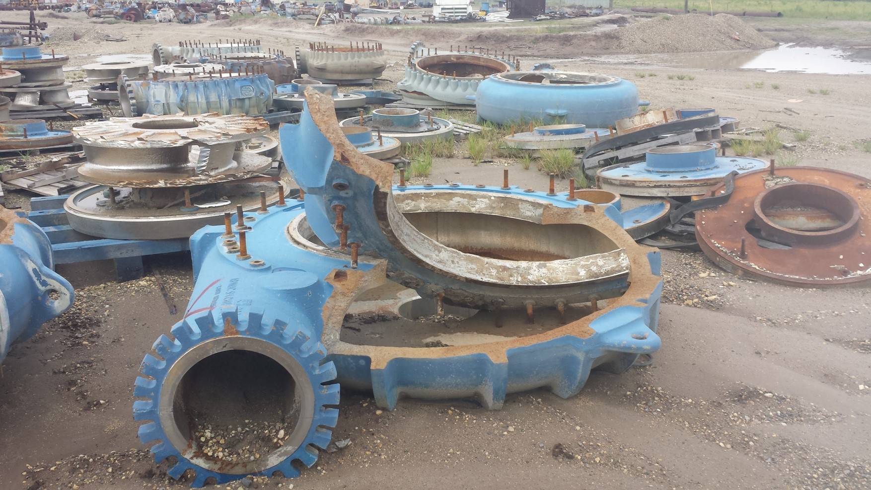
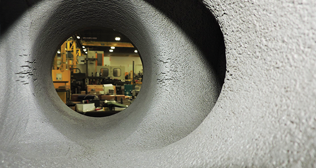
As illustrated in Figures 1 and 2, cavitation causes numerous pits to form on the module’s internal surface. Typically, cavitation pits create a stress concentration, which can reduce the module’s fatigue life.
To stop cavitation before it starts, install and tune high-speed pressure sensors on the mud suction line set to sound an alarm if the pressure falls below 30 psi.
Accelerometers can also be used to detect slight changes in module performance and can be an effective early warning system for cavitation prevention.
Although the pump may not be knocking loudly when cavitation first presents, regular inspections by a properly trained field technician may be able to detect moderate vibrations and slight knocking sounds.
Gardner Denver offers Pump University, a mobile classroom that travels to facilities and/or drilling rigs and trains rig crews on best practices for pumping equipment maintenance.
Severe cavitation will drastically decrease module life and will eventually lead to catastrophic pump failure. Along with downtime and repair costs, the failure of the drilling pump can also cause damage to the suction and discharge piping.
When a mud pump has entered full cavitation, rig crews and field service technicians will see the equipment shaking and hear the pump ‘knocking’… However, the process of cavitation starts long before audible signs reveal themselves – hence the name ‘the silent killer.’In 2017, a leading North American drilling contractor was encountering chronic mud system issues on multiple rigs. The contractor engaged in more than 25 premature module washes in one year and suffered a major power-end failure.
Gardner Denver’s engineering team spent time on the contractor’s rigs, observing the pumps during operation and surveying the mud system’s design and configuration.
The engineering team discovered that the suction systems were undersized, feed lines were too small and there was no dampening on the suction side of the pump.
Following the implementation of these recommendations, the contractor saw significant performance improvements from the drilling pumps. Consumables life was extended significantly, and module washes were reduced by nearly 85%.
Although pump age does not affect its susceptibility to cavitation, the age of the rig can. An older rig’s mud systems may not be equipped for the way pumps are run today – at maximum horsepower.

Pump cavitation is the formation of bubbles or cavities in the liquid, developed in areas of relatively low pressure around the eye of an impeller. As the bubbles/cavities travel to the discharge side of the pump, moving to a high pressure area, the cavities implode. The imploding or collapsing of these bubbles triggers intense shockwaves inside the pump, causing damage to the impeller, vibration, and excess noise.
So what’s the cause of cavitation? What causes those cavities to develop? Generally, it’s the lack of NPSHA (Net Positive Suction Head Available). Essentially, the pump is being starved of fluid. (Read more about how this can happen: 9 System Changes That Screw With NPSH)
In a perfect world, your pump should be sized properly for the application and your piping design should match. However, that"s not always possible. If you’re dealing with pump cavitation, be aware that there is technology and techniques available to detect, monitor, and prevent pump cavitation. Here"s a list of options available.
With cavitation comes vibration. One of the newest technologies on the market is able to detect higher than normal vibration levels and alert operators to the pump"s upset conditions. The i-ALERT®2 is very cost-effective and can be installed on any pump (or rotating equipment).
One of the best things about this technology is that it has datalogging capability. So if your pump is cavitating or experiencing upset conditions when no one is around, or on another shift, you"ll know about it.
There are a number of things you can try to prevent cavitation. You can re-evaluate the piping design leading to the pump, ensure the pump is running at its best efficiency point, among others. But there is also technology available for cavitation prevention.
ITT"s PumpSmart automatically right-sizes your pump to your system. The video below illustrates how cavitation is prevented when tank level is low, and NPSHA is too low.
Installing gauges within your pump system is always a good monitoring option. You can reference the gauges to understand where the pump is on the curve. If it is starting to fall off track, your pump might be having a cavitation problem that requires investigation.
Clogged filters are a common cause of cavitation issues. As debris and particulates gather in the filter, NPSHA is reduced if the pump is not sized correctly.
Automatic self-cleaning filters like Eaton’s DCF and MCFseries are popular choices for processes where production can’t be stopped. Self-cleaning filters are great because, as the name suggests, they clean themselves. Once installed, they automatically filter any solids or debris from whatever liquid you are pumping. They are known to improve pump efficiency while requiring minimal operator intervention. Click to see a video on how self cleaning filters work.
A duplex strainer, also known as a twin-basket strainer, filters and removes large particles of dirt or debris from liquid pumping systems. They never require downtime for cleaning because a valve is placed between the two baskets, changing the flow of liquid to one strainer while the other is being cleaned.
An ounce of prevention is worth a pound of cure, as they say, so it’s best to properly size your pump from the beginning and ensure the piping design fits the application.
But we know that flows and processes change over time, creating an unintentional chain of events that can sometimes cause a cavitation problem where there wasn’t one before. Take advantage of the technology now available to properly manage and monitor the pumps in your facility.
Still not sure how to resolve a potential cavitation problem? Contact us! We’re happy to provide technical assistance to businesses in Wisconsin and Upper Michigan.

Water hammer is a surge of pressure that can arise in pumping systems. The pressure is created when the pumping system undergoes an abrupt change in flow. The main causes of water hammering include opening and closing of valves, pump starts and stops, and separation and closure of the water columns. Due to these factors, the water column undergoes a change in momentum and this abrupt change can produce shock waves that travel back and forth within the system. Depending on the magnitude of the shock wave, physical damage in the system can be severe.
The phenomenon can be understood by an example in which water is pumped in a pipe that has valves on its both ends. The inlet valve is opened and the water column starts traveling towards the discharge valve. At this point, the discharge valve is closed instantly and the leading edge of the water column strikes the closed valve and begins to compress. A pressure wave (shock wave) begins to travel along the backstream (towards the inlet valve). The shock wave travels back and forth between the two valves until it finally diminishes due to friction losses. This water hammer shock wave is so fast that it can make a round trip between the two valves in less than half a second in the case of a 1000 feet pipe. The pressure created by this shock wave depends on the wave velocity (a), the velocity of water in the pipe (V), and the universal gravitational constant (g). Mathematically,

“Pump cavitationis, by definition, the formation and subsequent collapse or implosion of vapor bubbles in a pump. This usually occurs when gaseous bubbles are formed in the pump due to a drop in absolute pressure of the liquid below vapor pressure.”
The imploding or collapsing of these bubbles trigger intense shockwaves inside the pump and can cause many problems with the pump itself, but can also lead to system problems as well.
There are two types of cavitation: suction and discharge. Both types of cavitation have similar characteristics. Below is a list of possible causes of pump cavitation.
The causes listed above can lead to premature wear of the pumps impeller, pump housing, seals, and bearing assemblies. Cavitation can also cause poor flow conditions which could lead to poor heat transfer and poor system efficiency. (See examples below)
Conclusion:The next time you are called on to inspect or repair a circulating pump that you feel is possibly caveating, be sure to take a little extra time to observe the conditions before making any repairs. Simply repairing the pump is not enough. Find the problem which led to the problem and correct it first. Then you can proceed to make the necessary repairs to the pump. There are many ways to correct the problem if it is related to the incorrect pump. Contact R.L. Deppmann for tech support, replacement parts, pumps, or other solutions, such as VFD’s and balancing valves.
A county water treatment plant heard "cavitation-like noise" from their newly installed pumps and called MSI for help. Tests were conducted to see if damaging cavitation existed and how to best address the issue.
Why (problem/reason): Cavitation noise coming from the newly installed pumps had the customer worried. An attempt to change the suction pipe configuration and put straightener vanes in front of the pump suction did not help.
Findings: The flow traverse test on the suction piping revealed that the flow profile entering the pump was skewed and was the main reason for cavitation within the pump. Pictures taken of the impeller showed signs of cavitation damage. There was also a motor natural frequency within the operating speed range.
Impact: The findings suggested that the suction piping design needed to be modified in order to eliminate the skewed velocity profile causing the cavitation. A Computational Fluid Dynamic Analysis calibrated to the data collected on site was recommended to the customer. The CFD would help in the development of a solution to the flow problem with a greater chance of success upon implementation A motor pedestal redesign was recommended to shift the structural natural frequency above the running speed range

Cavitation is a physical phenomenon in which pressure differentials within a flowing liquid can quickly cause formation of vapor-filled cavities, or “bubbles.” The energy released when the bubbles collapse has the potential to create significant damage to the equipment, which could result in a system failure.
A typical process plant consists of numerous assets such as piping, pumps and valves. All such assets need maintenance, but the timing of maintenance is not always clear. Often, periodic maintenance is scheduled much too frequently. This could be costly if it requires the process to shut down. If operators are fully aware of the health status of all assets, they can accurately determine when maintenance is required rather than performing periodic maintenance inappropriately or, even worse, expensive repair work after a failure.
Process industries use large, highly complex pumps. Failure of such process critical pumps could result in downtime costs that exceed $200,000/day. Therefore, customers closely monitor these pumps and are strongly considering implementation of predictive maintenance solutions. Since cavitation can implode a pump and result in a major safety risk, customers are seeking a reliable solution that allows them to predict and prevent it.
Cavitation sensor data analysis leads to informed decision-making and strengthens operational process management in real-time. This intelligent innovative approach to eliminate pump cavitation will result in very high ROI for process users.
Existing cavitation detection systems monitor the pump and piping for abnormal sounds and vibration. By the time they report a problem, cavitation could be well underway. However, the Yokogawa system can accurately detect cavitation in pump much earlier by directly measuring the weak pressure fluctuation as a bubble collapses within the transmitter.
Yokogawa’s unique and patented technology enables customers to monitor process conditions in a pump to predict the onset of cavitation even before the first air bubble forms. This early detection of a possible pump cavitation allows plant operators to take appropriate action and prevent any damage to the pump.
Centerline Manufacturing is committed to the highest level of customer service quality. Every Centerline pump is comprehensively and repeatedly tested at diverse pressure levels to assure that it goes to our customer in perfect operational order. Centerline technicians work to ensure that our customers fully understand the operation of the model being delivered. If a customer"s pump is down, we understand the importance of timely response and parts availability. Centerline technicians will assess the problem and make repairs to bring the pump back into new specification. The Centerline mud pump technicians are well versed and qualified to operate and repair any product that is provided to the customer.

CFD has emerged as a useful tool in simulating the slurry flow as the liquid passes through different components of a pump. CFD analysts should be careful in applying the required form of mass and momentum conservation equations, use suitable discretization methods, utilize appropriate boundary conditions, apply suitable solver and the most important is to deduce and present the required results in a befitting manner. For pump wear problems, the selection of suitable erosion and cavitation model is vital. The work completed by various researchers in this field is not very old but is mature enough now. By using suitable scale down models and use of symmetry where appropriate, computational resources can be saved.
Roco and Addie [33] discussed an energy methodology to estimate the erosion from the solids concentration and velocity distributions near the walls. Simulations are performed for finite volume and finite element methods for the two-phase flow in pipelines and pump components. Noon et al. [16] conducted the simulation studies for the erosion prediction and as a consequence the head and efficiency losses for lime slurry flow through CP. A wear map, along with the simulation results, are obtained as shown in Figure 10. Figure 10a shows the wear map for erosion identification in the clockwise direction, which starts near the tongue. It can be observed that the tongue area near (θ = 35°) and the belly region around (θ = 302°) are the most-affected locations as shown in Figure 10d. It is found that erosion loss grows with an increase in solid particles’ impingement velocity, volumetric concentration and diameter.
Cavitation problem solving through numerical methods require substantial effort as the nature of the flow is quite complex. It needs fine integration and coupling between the conservation and cavitation modeling equations. Azizi et al. [36] presented a system for detection of cavitation severity in centrifugal pumps and for the improvement in its accuracy using a hybrid feature selection technique. A generalized regression neural network (GRNN) is used for cavitation identification. Xu et al. [37] studied the effects of surface topography on cavitation erosion. Regular oblique grooves, which were triangular or trapezoidal in appearance, were compared with sub-millimeter scale. Hattori et al. [38] proposed a prediction equation for cavitation wear. Material and liquid parameters were used to minimize the scattering of the prediction data. The kind of liquids, high liquid temperature, microstructure of constituents and the working life all influenced the cavitation. Liu et al. [39] performed numerical simulations with three different values of the flow coefficient, by utilizing modified k-ε turbulence model. The cavitating flow in the centrifugal pump obtained by the modified k-ε model at the design flow coefficient of 0.102 was selected. A lower value of pressure coefficient mainly occurs upstream of the impeller passage, which decreases the cavitation number, the cavity is generated on the suction side of the blade near the leading edge and then expands to the outlet of the impeller, while the downstream remains almost unaffected by the cavitation growth. The results showed good agreement with the experimental data. Fu et al. [40] studied the flow characteristics of centrifugal pumps under both steady and transient cavitation conditions. They found that centrifugal pumps used in nuclear reactors nearly become blocked and fractured due to bubble formation and burst. As a result, the axial force acting on the impeller rises and falls. It is also highlighted that transient cavitation conditions have a strong influence on the flow past in the impeller path. Nayebzadeh et al. [41] conducted experiments to study hydrodynamic cavitation in a micro channel containing a pillar. A high speed camera is utilized to capture the flow behavior. Figure 11 shows instantaneous velocity vectors near to the pillar and also indicates the flow behavior around the pillar. At the downstream of pillar, the vortex shedding is visible. The zoomed view presents the unsteady separation point at mid pillar.
Zhang and Chen [42] validated the numerical results with the experimental hydraulic performance curves. They showed that the filter-based model is better than the standard k-ε model to predict the parameters of hydraulic performance. A Boundary Vorticity Flux (BVF) method is presented to identify the cavitating flow fields. Results indicate that the effect of cavitation exists near the blade suction surface. Shao et al. [43] studied the viscous effects on the external performance and internal flow of the pump by using five types of molten salts as working fluids through CFD analysis. They used particle image velocimetry (PIV) to measure the flow fields inside the molten salt pump and the external performance was tested by utilizing water as a working fluid. The flow velocity and performance curves have been compared with the PIV observations. Zughbi et al. [44] presented a numerical-based energy model to predict erosion rate through local flow parameters. Important empirical coefficients for the CFD model were selected and compared with the experimental data set. Zhang et al. [45] conducted both the experimental and CFD work to study the erosion phenomenon in high pressure pipelines (HPP) during fracturing slurry flow. They have studied the failure analysis of high-pressure elbows, material erosion and erosion model establishment by making use of numerical predictions. Rossetti et al. [46] performed 3D transient CFD simulations and validated the results through experimental data for first stage rotary shaft pump and second stage centrifugal viscous pump. Numerical results helped to study the flow field inside the pumps in order to compute the hydraulic efficiency of the two stages and also to show the distribution of losses inside the pumps. Figure 12 shows the computational domains developed for the analysis.
Ye et al. [47] investigated the cavitation phenomenon in a CP through flow visualization experiments at various flow rates. Experimental and numerical results are compared for the pump head, cavity lengths and vapor fraction. They studied the relationship between the semi-analytical model with the experiments in the broad range of NPSH in comparison to Zwart model. Figure 13 shows the streamlines for three different NPSH at 60% of design flowrate, Qd inside the impeller. Both the cavity and the vortex around it develops as NPSH decreases. It is found that cavitation is an imperative source of vortex generation.
Transient phase CFD simulations were also executed to obtain a better understanding of the flow field and to associate the separation angle to the attached cavitation angle. Brunhart et al. [48] devised a methodology to evaluate the viability of several cavitation erosion risk indicators. The distribution and intensity of the resulting ERIs were evaluated. It was anticipated that using these risk indicators will be useful product design and development which will save considerable time and cost.
Ramirez et al. [49] used a design of experiment technique for the characterization and optimization phenomena in dredging centrifugal pumps. Various parameters such as swing speed, dredging depth and inclination and impeller rpm were analyzed.


 8613371530291