
mud pump cavitation price

Cavitation is an undesirable condition that reduces pump efficiency and leads to excessive wear and damage to pump components. Factors that can contribute to cavitation, such as fluid velocity and pressure, can sometimes be attributed to an inadequate mud system design and/or the diminishing performance of the mud pump’s feed system.
Although cavitation is avoidable, without proper inspection of the feed system, it can accelerate the wear of fluid end parts. Over time, cavitation can also lead to expensive maintenance issues and a potentially catastrophic failure.
When a mud pump has entered full cavitation, rig crews and field service technicians will see the equipment shaking and hear the pump “knocking,” which typically sounds like marbles and stones being thrown around inside the equipment. However, the process of cavitation starts long before audible signs reveal themselves – hence the name “the silent killer.”
Mild cavitation begins to occur when the mud pump is starved for fluid. While the pump itself may not be making noise, damage is still being done to the internal components of the fluid end. In the early stages, cavitation can damage a pump’s module, piston and valve assembly.
The imperceptible but intense shock waves generated by cavitation travel directly from the fluid end to the pump’s power end, causing premature vibrational damage to the crosshead slides. The vibrations are then passed onto the shaft, bull gear and into the main bearings.
If not corrected, the vibrations caused by cavitation will work their way directly to critical power end components, which will result in the premature failure of the mud pump. A busted mud pump means expensive downtime and repair costs.
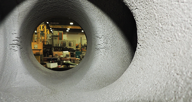
As illustrated in Figures 1 and 2, cavitation causes numerous pits to form on the module’s internal surface. Typically, cavitation pits create a stress concentration, which can reduce the module’s fatigue life.
To stop cavitation before it starts, install and tune high-speed pressure sensors on the mud suction line set to sound an alarm if the pressure falls below 30 psi.
Accelerometers can also be used to detect slight changes in module performance and can be an effective early warning system for cavitation prevention.
Although the pump may not be knocking loudly when cavitation first presents, regular inspections by a properly trained field technician may be able to detect moderate vibrations and slight knocking sounds.
Gardner Denver offers Pump University, a mobile classroom that travels to facilities and/or drilling rigs and trains rig crews on best practices for pumping equipment maintenance.
Severe cavitation will drastically decrease module life and will eventually lead to catastrophic pump failure. Along with downtime and repair costs, the failure of the drilling pump can also cause damage to the suction and discharge piping.
When a mud pump has entered full cavitation, rig crews and field service technicians will see the equipment shaking and hear the pump ‘knocking’… However, the process of cavitation starts long before audible signs reveal themselves – hence the name ‘the silent killer.’In 2017, a leading North American drilling contractor was encountering chronic mud system issues on multiple rigs. The contractor engaged in more than 25 premature module washes in one year and suffered a major power-end failure.
Gardner Denver’s engineering team spent time on the contractor’s rigs, observing the pumps during operation and surveying the mud system’s design and configuration.
The engineering team discovered that the suction systems were undersized, feed lines were too small and there was no dampening on the suction side of the pump.
Following the implementation of these recommendations, the contractor saw significant performance improvements from the drilling pumps. Consumables life was extended significantly, and module washes were reduced by nearly 85%.
Although pump age does not affect its susceptibility to cavitation, the age of the rig can. An older rig’s mud systems may not be equipped for the way pumps are run today – at maximum horsepower.

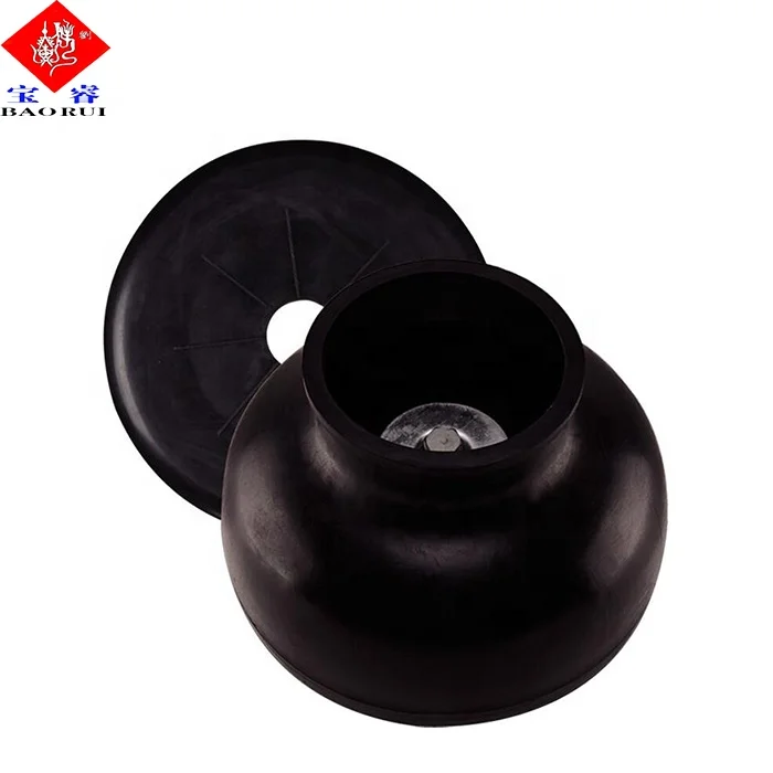
A well-placed suction stabilizer can also prevent pump chatter. Pump chatter occurs when energy is exchanged between the quick opening and closing of the reciprocating pump’s valves and the hammer effect from the centrifugal pump. Pump isolation with suction stabilizers is achieved when the charge pumps are isolated from reciprocating pumps and vice versa. The results are a smooth flow of pumped media devoid of agitating energies present in the pumped fluid.
I’ve run into several instances of insufficient suction stabilization on rigs where a “standpipe” is installed off the suction manifold. The thought behind this design was to create a gas-over-fluid column for the reciprocating pump and eliminate cavitation.
When the standpipe is installed on the suction manifold’s deadhead side, there’s little opportunity to get fluid into all the cylinders to prevent cavitation. Also, the reciprocating pump and charge pump are not isolated.
Installing a suction stabilizer from the suction manifold port supports the manifold’s capacity to pull adequate fluid and eliminates the chance of manifold fluid deficiency, which ultimately prevents cavitation.
The suction stabilizer’s compressible feature is designed to absorb the negative energies and promote smooth fluid flow. As a result, pump isolation is achieved between the charge pump and the reciprocating pump.
The isolation eliminates pump chatter, and because the reciprocating pump’s negative energies never reach the charge pump, the pump’s expendable life is extended.
Investing in suction stabilizers will ensure your pumps operate consistently and efficiently. They can also prevent most challenges related to pressure surges or pulsations in the most difficult piping environments.
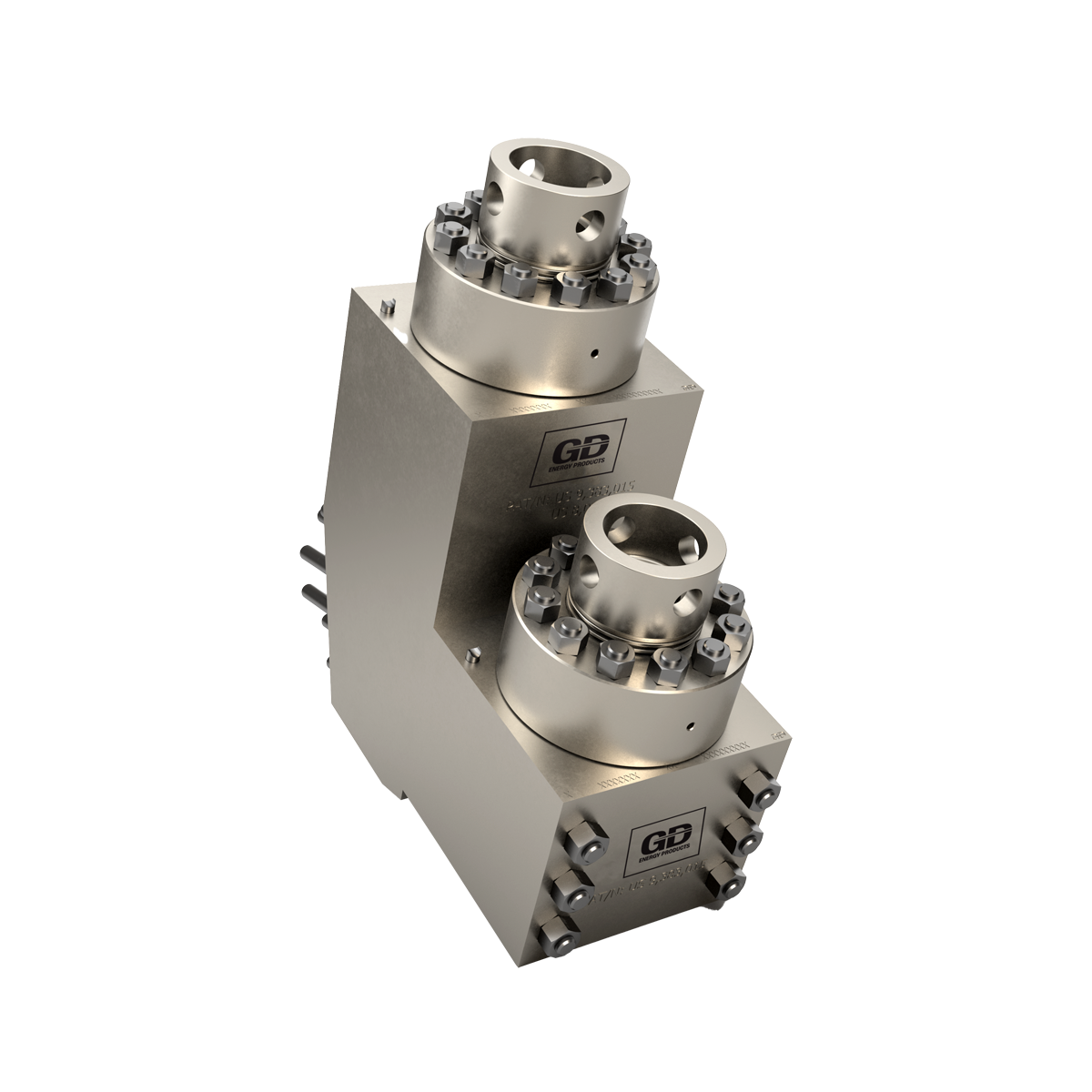
GD Energy Products’ Y-Shaped module is engineered to provide unrivalled reliability. The unique design reduces the stress placed on the module’s cross-bore intersection, maximizing service life and reducing the risk of cavitation. Constructed from premium, heat-treated forgings ensures that our module can withstand the highest pressures, in even the most demanding conditions.

Mud pump cavitation: Routineinspections, maintenance canprevent ‘silent killer’ from reducingrig efficiency, equipment reliabilityWith pumps being run at max horsepower at today’s well sites, best practicescan help contractors to avoid premature damage, extend consumables life
CAVITATION IS AN UNDESIR ABLE will see the equipment shaking and hear the a sealing surface. These unexpected failurescondition that causes a reduction in pump pump “knocking,” which typically sounds are expensive and lead to a minimum ofefficiency and excessive wear/damage to like marbles and stones being thrown around eight hours of rig downtime for modulepump components. Factors that can contrib- inside the equipment. However, the process replacement.ute to cavitation, such as fluid velocity and of cavitation starts long before audible signspressure, can sometimes be attributed to an reveal themselves – hence the name, “the PREVENTING CAVITATIONinadequate mud system design and/or the silent killer.” Stopping cavitation before it starts is adiminishing performance of the mud pump’s Mild cavitation begins to occur when matter of routine inspection and mainte-feed system. the mud pump is “starved” for fluid. While nance. For starters, install and tune high- Other factors contributing to cavitation the pump itself may not be making noise, speed pressure sensors on the mud suctioninclude: damage is still being done to the internal line to alarm if the pressure falls below • Improper sizing of charge pump; components of the fluid end. Mild cavita- 30 psi. Accelerometers can also be used to • Improper maintenance of charge pump tion damages the module, piston and valve detect slight changes in module performanceimpellers – worn impellers cause a reduction assembly. These hidden and intense shock and can be a good early warning systemof fluid pressure; waves generated by cavitation travel directly for cavitation prevention. Routinely conduct • Dirty or clogged charge pump feed and from the fluid end to the pump’s power end, visual inspections on the pump. While thedischarge lines; causing premature damage (vibration) to knocking may not be loud, if inspections are • Improper size of plumbing from charge the crosshead slides, thus passing onto the conducted on a regular basis, a field techni-pump to mud pump; shaft, bull gear and into the main bearings. cian will be able to detect moderate vibra- • Elevation changes and excessive elbows If not corrected, the vibrations caused by tions or knocking sounds. Finally, maintainin plumbing from mud tank to mud pump; cavitation will work their way directly to the gear end of the pump and check oil on aand these critical power end components, caus- regular basis. • Lack of/or inadequate suction and dis- ing premature failure, expensive downtime Gardner Denver offers Pump Universitycharge dampening. and repair costs. (PumpU), a mobile classroom that travels to Cavitation is an avoidable issue, but with- As referenced in Figures 1 and 2, the customers’ facilities and/or drilling rigs andout proper inspection of the feed system it process of cavitation causes numerous pits trains rig crews on how to properly maintaincan accelerate the wear of fluid end parts. Tis to form on the module’s internal surface. pumping equipment. Participants in thecan lead to expensive maintenance issues and Typically, cavitation pits result in a stress program have found that their improveda potentially catastrophic failure. concentration that results in a reduced maintenance skills have extended the life fatigue life of the module. Washouts are one of fluid end expendables on their sites, inMILD VS SEVERE CAVITATION of the leading causes of module failure and addition to lowering repair costs, decreasing When a mud pump has entered full cavita- take place when the high-pressure fluid cuts production costs and reducing workplacetion, rig crews and field service technicians through the module’s surface and damages hazards.
FIGURES 1 (LEFT) AND 2: Long-term, severe cavitation can cause surface pitting on a module crossbore and reduce the module’s fatigue life. Overtime, cavitation can lead to expensive maintenance issues and a potentially catastrophic failure.
RESULTS OF CAVITATION formance. Consumables life has been extend- The best way to prevent pump cavitation At the onset of cavitation, there will be ed significantly, and module washes have is to check the system’s feed lines and equip-reduced life in expendables and gradual wear been reduced by nearly 85%. This improved ment daily for any signs of abnormal noise oron the modules and power end. Severe cavi- performance has drastically reduced rig vibrations. Although it’s impractical to flushtation will drastically decrease module life downtime and has increased the operational system piping during drilling operations,and will eventually lead to catastrophic pump efficiency and customer satisfaction for the strainer screens should be checked daily tofailure, causing unwanted and costly down- drilling contractor. remove any debris or other flow restrictions.time. In addition, failure of the drilling pump Additionally pre-charge (centrifugal) pumpscan also cause damage to the suction and THE IMPACT OF TODAY’S DRILLING should be inspected regularly to ensure out-discharge piping. RIGS put flow and pressure is adequate. Following While pump age does not affect its sus- these simple steps will allow you to achieveCAVITATION IN THE FIELD ceptibility to cavitation, the rig’s age can. maximum performance from your pumping A leading North American drilling con- Oftentimes, a rig’s mud systems aren’t equipment and reduce unplanned equipmenttractor encountered chronic mud system equipped for the way pumps are run today – outages. DCissues on multiple rigs. The company expe- at maximum horsepower.rienced more than 25 premature modulewashes in one year and a major power-endfailure. Gardner Denver’s engineering teamwas called and spent time on the contractor’s When a mud pump has entered fullrigs observing the pumps during operation
technicians will see the equipment shakingtems were undersized, feed lines were toosmall and there was no dampening on thesuction side of the pump. There were also
and hear the pump ‘knocking’... However,issues with the feed line maintenance – linesweren’t cleaned out on a regular basis andsolids from the fluid had formed a thick cake
the process of cavitation starts long beforeon the bottom of the pipe, further reducingits diameter. The engineering team recom-mended increasing the diameter of the feed
audible signs reveal themselves – hence thelines and routine cleanings to improve flowand reduce the risk of cavitation. Following the implementation of these
Pump cavitation is the formation of bubbles or cavities in the liquid, developed in areas of relatively low pressure around the eye of an impeller. As the bubbles/cavities travel to the discharge side of the pump, moving to a high pressure area, the cavities implode. The imploding or collapsing of these bubbles triggers intense shockwaves inside the pump, causing damage to the impeller, vibration, and excess noise.
So what’s the cause of cavitation? What causes those cavities to develop? Generally, it’s the lack of NPSHA (Net Positive Suction Head Available). Essentially, the pump is being starved of fluid. (Read more about how this can happen: 9 System Changes That Screw With NPSH)
In a perfect world, your pump should be sized properly for the application and your piping design should match. However, that"s not always possible. If you’re dealing with pump cavitation, be aware that there is technology and techniques available to detect, monitor, and prevent pump cavitation. Here"s a list of options available.
With cavitation comes vibration. One of the newest technologies on the market is able to detect higher than normal vibration levels and alert operators to the pump"s upset conditions. The i-ALERT®2 is very cost-effective and can be installed on any pump (or rotating equipment).
One of the best things about this technology is that it has datalogging capability. So if your pump is cavitating or experiencing upset conditions when no one is around, or on another shift, you"ll know about it.
There are a number of things you can try to prevent cavitation. You can re-evaluate the piping design leading to the pump, ensure the pump is running at its best efficiency point, among others. But there is also technology available for cavitation prevention.
ITT"s PumpSmart automatically right-sizes your pump to your system. The video below illustrates how cavitation is prevented when tank level is low, and NPSHA is too low.
Installing gauges within your pump system is always a good monitoring option. You can reference the gauges to understand where the pump is on the curve. If it is starting to fall off track, your pump might be having a cavitation problem that requires investigation.
Clogged filters are a common cause of cavitation issues. As debris and particulates gather in the filter, NPSHA is reduced if the pump is not sized correctly.
Automatic self-cleaning filters like Eaton’s DCF and MCFseries are popular choices for processes where production can’t be stopped. Self-cleaning filters are great because, as the name suggests, they clean themselves. Once installed, they automatically filter any solids or debris from whatever liquid you are pumping. They are known to improve pump efficiency while requiring minimal operator intervention. Click to see a video on how self cleaning filters work.
A duplex strainer, also known as a twin-basket strainer, filters and removes large particles of dirt or debris from liquid pumping systems. They never require downtime for cleaning because a valve is placed between the two baskets, changing the flow of liquid to one strainer while the other is being cleaned.
An ounce of prevention is worth a pound of cure, as they say, so it’s best to properly size your pump from the beginning and ensure the piping design fits the application.
But we know that flows and processes change over time, creating an unintentional chain of events that can sometimes cause a cavitation problem where there wasn’t one before. Take advantage of the technology now available to properly manage and monitor the pumps in your facility.
Still not sure how to resolve a potential cavitation problem? Contact us! We’re happy to provide technical assistance to businesses in Wisconsin and Upper Michigan.

The majority of problems occurring with reciprocating pumps originate on the suction side of the pump. The term “suction” can be misleading due to the fact that single acting pumps do not lift liquid or suck. A better term to use is “the line leading to the inlet manifold on the pump.” Single acting pumps rely upon atmospheric pressure to force the liquid into a low pressure area created by the completed discharge stroke of the piston or a centrifugal pump with sufficient head and flow to deliver liquid to the inlet manifold as needed.
The inlet side of the pump is critical to correct operation. Collapsible hose should never be used on the inlet side and length is always a factor because friction loss will enter the picture. The inlet line should have a large inside diameter, straight and short as possible. This type system yields a huge benefit to the cost of overall maintenance of the pump. The inlet to the pump should be as close to the supply source as possible and sized according to the discharge flow of the pump. Never decrease the inlet manifold diameter of the liquid end in order to use a smaller inlet hose. Always increase the inlet hose by 1 or 2 in. to ensure good inlet conditions for the pump. The inlet velocity should never be less than 1 ft per second or greater than 3 ft per second.
When problems start to occur on the inlet side, those problems can be both visual and audible. The inlet line will start to pulsate. This occurs because of the liquid accelerating and decelerating rapidly. On each rotation of a triplex crankshaft, one inlet valve will be closed and another will be partially open. The third will be fully open on the discharge stroke. This movement of the valves causes the liquid within the supply line to try and stop, start toward the pump and reverse toward the supply all at the same time. Therefore, poorly designed supply lines will show this movement in pulsating form.
This pulsation can also be audible within the pump. You will hear hammering and if severe enough, the discharge line will also began to pulse. If this much cavitation is occurring within the pump, severe damage can and will occur within the power end as well as the liquid end if conditions are not changed. The hammering sound is the audible form of pump cavitation.
Cavitation is caused by insufficient flow or head from the supply tank to the inlet of the pump and the smooth transition from the manifold through the throat of the inlet valve. If the liquid is too viscous or the supply of the liquid is insufficient to meet the required speed (gpm) of the pump, gasses will start to break out of the liquid and form bubbles in the slurry as it passes through the throat of the inlet valve. When the pump is on the discharge stroke and pressure starts to build rapidly from atmosphere to discharge pressure, the bubbles start to implode and cause damage to liquid end components as well as the liquid end itself.
A suction valve or inlet valve is nothing more than an orifice within the system. The suction manifold of the pump should be filled with liquid and moving at a consistent flow rate. As an inlet valve begins to open and liquid flows through, the liquid should be in contact with the face of the piston. This column of liquid should move at the same rate as the piston. If the inlet is inadequate or pump speed too great, gas will break from the liquid in the low pressure zone created by the inlet seat and bubbles will from in the pumping chamber or atmosphere will enter through the liner and piston. Either way, the pumping chamber will not be filled with liquid.
When the discharge stroke begins, the piston is at rest. Half way through the discharge stroke, the piston is traveling at maximum velocity. Ideally, the pumping chamber should be filled with liquid and in contact with the face of the piston. The inlet valve within that chamber should have just closed as the piston starts the discharge stroke. If bubbles have formed, the chamber is only partially filled with liquid. As pressure starts to build within the chamber, the bubbles implode and the piston encounters a partially filled chamber traveling at maximum velocity slamming open the discharge valve and causing a shock wave to be sent throughout the entire system.
If a pump has a satisfactory inlet system, the end user will see the results of that in his hip pocket. If not, he will help support the entire industry with more equipment sales.

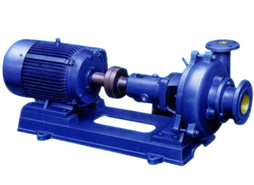
Centrifugal pumps are one of the most common types used in industry. It’s a device that pumps mud for solids control equipment. Figure 1 shows a generic, single stage centrifugal pump and Figure 2 illustrates a multistage centrifugal pump.
These pumps can utilize either open or closed impellers and may have single or multiple stage designs. Centrifugal pumps utilize Bernoulli’s principle to develop pressure (see Bernoulli’s Principle Explained below) by first increasing the fluid velocity inside an impeller and then decreasing the fluid velocity in the discharge nozzle. These pumps consist of a shaft with bearings for support and an impeller as well as a pump casing. To prevent leakage from the pump casing to the atmosphere, most pumps employ packing, single or dual mechanical shaft seals.
Centrifugal pump performance is typically presented graphically with a series of curves similar to the group shown in Figure 3. The manufacturer usually provides curves that describe how flow, differential head, net positive head required, and efficiency change with pump flow.
B. If a centrifugal pump has more than one impeller inside of it is called a multistage pump. If it has, for example five impellers in it, then it is a five stage pump
Centrifugal pumps may be operated in a series or parallel (see Figure 1.4) configuration. When operating pumps in series, the pressure is increased across each pump, but the flow through each pump is identical (minus any minor flow losses due to leakage). When operating in parallel, the pressure rise on each pump is identical, but the total flow is increased. However, the overall flow is not doubled with two pumps operating in parallel because of “system head” or pressure.
The easiest way to understand system head is to remember that the discharge pipe size stays the same diameter and therefore tends to restrict the higher flow generated by two pumps operating in parallel. This bottleneck effect means that two pumps operating in parallel will always deliver less than twice the flow that one pump can deliver.
The last rule is the reason centrifugal pumps and centrifugal compressors are able to convert a high velocity flow from a rotating impeller into high pressure.
Cavitation is a serious operating condition that sounds like gravel is passing through a pump. This unique “gravelly” sound associated with cavitation is due to the fact that vapor cavities or bubbles are continually forming and then collapsing in the pump’s inlet. If cavitation is not addressed and corrected quickly, the internal components of a centrifugal or positive displacement pump may be seriously damaged.
Cavitation is caused by either 1) operating a pump too close to the boiling point of the liquid at its suction or 2) by trying to pump more than a pump is designed to handle. Pump designers use a term called net positive suction head (NPSH) to determine whether there is enough suction pressure to prevent cavitation. Typical net positive suction head requirements can be seen in Figure 1.3 (Centrifugal Pump Curves), where they are depicted as dotted vertical lines, labeled: 2′, 2.5′, 3′, 3.5′, 4′, 4.5′. 2′ means that at this particular flow, two feet of liquid suction head is required to prevent cavitation, 2.5′ means that at this particular flow, two and a half feet of liquid suction head is required to prevent cavitation, and so forth.
As an operator, you simply need to remember that the higher the flow rate out of a pump the greater the suction pressure must be to insure that cavitation does not take place. An operator is in the position to control some parameters that will affect NPSHA. For example, if the pump is taking suction from a tower or tank, either the liquid level or the pressure can be increased as a means of stopping or reducing pump cavitation. Reducing the pump flow can have a positive effect on the NPSHA as well and may stop cavitation.
When you detect a pump problem and decide to act, always list the symptom or symptoms that were noted on the work request, such as not enough pressure or flow, a seal is leaking, the drive motor is tripping off line, there is high vibration on the pump, etc. Do not list what should be done about the suspected problem on the work request. Comments such as: fix the pump, change the pump, replace the pump, etc. are not helpful to the maintenance planner. Comments such as: Seized, vibrating, low pressure, tripping offline, etc. are helpful. Always, allow the maintenance crew to investigate the situation and perform what they think are the necessary corrections, adjustments or repairs.
Anyone on a location when it is happening knows for certain what is happening when a positive displacement or triplex pump starts to cavitate. The characteristic knocking starts up, sometimes barely noticeable and sometimes rising to a deafening hammering sound. On some occasions it will sound like a thump like a badly balanced washing machine, and on others it will sound like someone inside the pump banging on it randomly with a sledgehammer. But what is going on INSIDE the pump when you hear this outside the pump? (note – if you aren’t familiar with the operation of triplex pumps and other positive displacement pumps you can go here for a great basic tutorial: http://www.drillingformulas.com/basic-understanding-about-positive-displacement-in-drilling-industry/ or here for just a video:
The short answer to what’s going on is that somewhere there is air inside the pump. Let’s take the example of a triplex pump circulating at 3,000 psi (207 bars)Lets suppose that some air gets in from outside the pump at the inlet conditions of the pump – usually somewhere around 50 psi (3 bars).
When the cylinder starts to push forward on the power/discharge part of the cycle, the discharge valve opens, and it is exposed to the 3,000 psi (207 bars) in the outflow side of the pump system. This is 70 times higher than our inlet pressure was. Suddenly the air in the pump has been compressed a size about 70 times smaller than it was before the piston began the discharge part of the cycle. The air bubbles collapse and the work that was being done in the pump to push the otherwise relatively uncompressible liquid out of the pump by the drive rod on the piston suddenly drops nearly to zero for as long as it takes for the piston to ‘catch up’ and compress the air to the new equilibrium volume.
In a triplex pump, only one cylinder is in the compression/discharge stage at any given time, so when there is no constant discharge of fluid taking place while the air is getting compressed, suddenly the load on the driveshaft, engine and power end of the pump is close to zero briefly then shoots back up to normal as the air is compressed to 3,000 psi (207 bars) This causes the knocking and banging sounds as the different parts of the engine and power end rapidly change speeds, move from tension to compression, hit bearings, etc. So how did the air get in the system?
The simplest answer is that it was already there. A positive displacement pump will not draw or pull fluid into it. There must be some other type of pump or pressure or gravity forcing fluid into the pump for it to operate. If that process, called priming was not done correctly it may have left some air in the piping that is in between the source of the fluid and the pump. It only takes a small amount of air trapped somewhere in the intake system to create knocking and cavitation. If this is the source of the problem, it will tend to go away after a short period of use. If the fluid source is changed, the lines and piping for the inlet system altered or the pump is started or stopped briefly it can come back again. This is especially the case if the properties of the fluids being pumped change – for example switching from a low viscosity fluid to cement is notorious for causing issues in systems where the intake system is not properly purged and prepared. Sometimes these issues are so bad that it becomes difficult to conduct a good cement job because the volume of fluids being pumped cannot be rapidly and accurately measured with common equipment.
It can be the case that the intake lines instead of leaking fluid out (which might be obvious) there is a place where air is leaking IN. this is almost always between the fluid source and the centrifugal charge pump for the triplex. Between the charge pump and the positive displacement pump, the fluid usually has enough pressure that it leaks out, but sometimes between these two points the pressure is low enough for air to leak in. If general checking for tight connections and good seals does not solve the problem these problems can be hard to track down. In some cases it may be necessary to stop pumping and turn the centrifugal pump off in order to be able to look for the source of the pumping fluid which can now leak outwards under gravity from the fluid source without the suction from the centrifugal charge pump on the system. This is obviously a sort of problem you want to discover and resolve before getting into a critical situation. These problems tend to occur in temporary lines, in systems which have been used to pump solvents or acids which destroy seals in the suction system, in systems which are used to pump cement or other abrasives which damage the lines, and in systems which are permanent but which have not been maintained and checked on a regular basis. One final area which is often overlooked is to watch for leakage on/in the seals of the central shaft of the centrifugal pump itself.
So your system is properly primed up, and you checked your suction system for leaks but the pump is STILL having issues. No idea where the air is getting in. In fact, there might not be any leaks or residual air in the system. This leads to one final potential problem and that is low charge pressure. Typical inlet pressure for a positive displacement pump is somewhere around 50 psi (3 bars) but this number is usually measured at the charge pump itself. Between the charge pump and the positive displacement pump there is inevitably some piping, and of course there are the valves on the triplex pump itself which are usually spring loaded to ensure they close properly and must be pushed open by the charge pressure for the pump. If the pressure and associated feed rate of the system gets too low by the time it reaches the positive displacement pump, then some odd non-intuitive things occur.
At one atmosphere/1 bar water boils at 100 degrees Celsius (212 F) but what if the inlet pressure to the pump is lower than this? When the piston on the pump begins to pull back something must come in through the inlet valve and fill the space being made in there. If fluid is not coming in fast enough to fill up the space with liquid, then some of the liquid will begin to boil off at room temperature to make up the difference. At ~ 0.15 bars (2 psi) water boils at room temperature. The resulting steam (steam at room temperature!) then fills the space in the piston. Now that it is a gas, it acts exactly like our air did when we looked at what causes cavitation in the first place. When the piston starts the discharge stroke it compresses, and in addition unlike air it recondenses into liquid and in both cases causing all that knocking and equipment damage.
How do we diagnose and resolve this? Usually if the problem is a lack of charge pressure it will not be present at low discharge rates (because the charge system can keep up) but it will begin and worsen as discharge rates increase. It will also get worse with thick viscous fluids like cement or heavy pills because they have more friction in the piping between the charge pump and the positive displacement pump, making it harder for the charge rate to keep up. This can occur suddenly and unexpectedly when switching from a relatively low viscosity working fluid to a higher viscosity one. It will also get worse if materials with a low vapor pressure like xylene, toluene or other flammable and combustible solvents. This is because they already boil at a low temperature and have a high vapor pressure – it does not take a lot of loss of inlet pressure before a lot of vapor is developed by these fluids. The solutions are in two parts: increasing the charge pressure and decreasing the losses between the charge point and the positive displacement pump. Sometimes this means using a ‘boost’ charging pump closer to the positive displacement pump than the normal one – other times it means bypassing the normal charging pump in favor of a larger temporary one. Decreasing pressure losses between the charging point and the pump can be done if piping and lines can be shortened, straightened made larger diameter or if excessive valves and junctions can be avoided. Another way to reduce pressure losses in some cases is by selecting valves and seats on the pump which have a larger inlet area and/or a weaker return spring.
Cavitation and pump knocking are often created by complicated problems, but usually have simple solutions. In situations where there are consistently issues, a careful consideration of the causes and ways to prevent them will usually resolve the issues. For any given type of pump system and installation experienced crews and operators will learn to recognize the limitations of the systems and how to resolve them. It is good practice to write these things down and ensure they do not get ‘lost’ because the wrong person is on vacation or retires! Having a quick reference of best practices and issues for the systems and fluids commonly used can avoid major difficulties with ‘known problems’ and can also predict the sorts of problems and solutions for fluid systems and combinations which aren’t as well understood through experience.

From a technical standpoint, cavitation occurs when the absolute pressure at the eye of the impeller reaches the vapor pressure. At this pressure, bubbles or “cavities” form in the liquid. As the bubbles move from the low-pressure area near the impeller toward the high-pressure area surrounding the pump discharge, they implode.
These little implosions of collapsing bubbles cause loud popping noises, which operators can hear externally while their pumps are operating. Internally, this repeated popping creates shockwaves that can result in considerable physical damage. Over time, cavitation can destroy impellers and pump housing, result in seal and bearing failure, impact flow and pressure rates, and consume significantly more power.
Depending on your application and setup, you could be experiencing suction cavitation or discharge cavitation. In either case, the end result can be very damaging — and very costly — to repair or replace.
Did you know pump vibration levels are an excellent diagnostic tool?Click here to view the GIW® Minerals chart of Pump Vibration Levels to see how your pump is holding up.
As far as general maintenance is concerned, it’s important to ensure your pipe and filters are free of blockages and that your pump is operating at its most efficient point on its pump curve. However, the most effective form of prevention is to select the right pump from the start. Find a centrifugal pump that operates far below the required critical suction pressure or net positive suction head (NPSH). It’s also important that your system’s flow in and out of the pump doesn’t exceed the pump’s capabilities.
By selecting a pump that’s an ideal fit for your pressure, flow, and overall application, cavitation should never be a concern. If you fear that cavitation is affecting your operations, it’s a good idea to get in touch with an expert who can help you diagnose precisely why. With the right pump — and the right partner — you can avoid this costly and catastrophic problem!
The GIW Tech Services slurry pump experts can ensure you have the right pump for the job so cavitation doesn’t harm your system — or your bottom line. Contact us today to see what our highly experienced crew can do for you.

Centrifugal pumps basically consist of a stationary pump casing and an impeller mounted on a rotating shaft. The pump casing provides a pressure boundary for the pump and contains channels to properly direct the suction and discharge flow. The pump casing has suction and discharge penetrations for the main flow path of the pump and normally has small drain and vent fittings to remove gases trapped in the pump casing or to drain the pump casing for maintenance.
Some centrifugal pumps contain diffusers. A diffuser is a set of stationary vanes that surround the impeller. The purpose of the diffuser is to increase the efficiency of the centrifugal pump by allowing a more gradual expansion and less turbulent area for the liquid to reduce in velocity. The diffuser vanes are designed in a manner that the liquid exiting the impeller will encounter an everincreasing flow area as it passes through the diffuser. This increase in flow area causes a reduction in flow velocity, converting kinetic energy into flow pressure.
Impellers of pumps are classified based on the number of points that the liquid can enter the impeller and also on the amount of webbing between the impeller blades.
Centrifugal pumps can be classified based on the manner in which fluid flows through the pump. The manner in which fluid flows through the pump is determined by the design of the pump casing and the impeller. The three types of flow through a centrifugal pump are radial flow, axial flow, and mixed flow.
A centrifugal pump with a single impeller that can develop a differential pressure of more than 150 psid between the suction and the discharge is difficult and costly to design and construct. A more economical approach to developing high pressures with a single centrifugal pump is to include multiple impellers on a common shaft within the same pump casing. Internal channels in the pump casing route the discharge of one impeller to the suction of another impeller. Figure 9 shows a diagram of the arrangement of the impellers of a four-stage pump. The water enters the pump from the top left and passes through each of the four impellers in series, going from left to right. The water goes from the volute surrounding the discharge of one impeller to the suction of the next impeller.
Centrifugal pumps vary in design and construction from simple pumps with relatively few parts to extremely complicated pumps with hundreds of individual parts. Some of the most common components found in centrifugal pumps are wearing rings, stuffing boxes, packing, and lantern rings. These components are shown in Figure 10 and described on the following pages.
Some wear or erosion will occur at the point where the impeller and the pump casing nearly come into contact. This wear is due to the erosion caused by liquid leaking through this tight clearance and other causes. As wear occurs, the clearances become larger and the rate of leakage increases. Eventually, the leakage could become unacceptably large and maintenance would be required on the pump.
To minimize the cost of pump maintenance, many centrifugal pumps are designed with wearing rings. Wearing rings are replaceable rings that are attached to the impeller and/or the pump casing to allow a small running clearance between the impeller and the pump casing without causing wear of the actual impeller or pump casing material. These wearing rings are designed to be replaced periodically during the life of a pump and prevent the more costly replacement of the impeller or the casing.
In almost all centrifugal pumps, the rotating shaft that drives the impeller penetrates the pressure boundary of the pump casing. It is important that the pump is designed properly to control the amount of liquid that leaks along the shaft at the point that the shaft penetrates the pump casing. There are many different methods of sealing the shaft penetration of the pump casing. Factors considered when choosing a method include the pressure and temperature of the fluid being pumped, the size of the pump, and the chemical and physical characteristics of the fluid being pumped.
One of the simplest types of shaft seal is the stuffing box. The stuffing box is a cylindrical space in the pump casing surrounding the shaft. Rings of packing material are placed in this space. Packing is material in the form of rings or strands that is placed in the stuffing box to form a seal to control the rate of leakage along the shaft. The packing rings are held in place by a gland. The gland is, in turn, held in place by studs with adjusting nuts. As the adjusting nuts are tightened, they move the gland in and compress the packing. This axial compression causes the packing to expand radially, forming a tight seal between the rotating shaft and the inside wall of the stuffing box.
The high speed rotation of the shaft generates a significant amount of heat as it rubs against the packing rings. If no lubrication and cooling are provided to the packing, the temperature of the packing increases to the point where damage occurs to the packing, the pump shaft, and possibly nearby pump bearings. Stuffing boxes are normally designed to allow a small amount of controlled leakage along the shaft to provide lubrication and cooling to the packing. The leakage rate can be adjusted by tightening and loosening the packing gland.
It is not always possible to use a standard stuffing box to seal the shaft of a centrifugal pump. The pump suction may be under a vacuum so that outward leakage is impossible or the fluid may be too hot to provide adequate cooling of the packing. These conditions require a modification to the standard stuffing box.
One method of adequately cooling the packing under these conditions is to include a lantern ring. A lantern ring is a perforated hollow ring located near the center of the packing box that receives relatively cool, clean liquid from either the discharge of the pump or from an external source and distributes the liquid uniformly around the shaft to provide lubrication and cooling. The fluid entering the lantern ring can cool the shaft and packing, lubricate the packing, or seal the joint between the shaft and packing against leakage of air into the pump in the event the pump suction pressure is less than that of the atmosphere.
In some situations, packing material is not adequate for sealing the shaft. One common alternative method for sealing the shaft is with mechanical seals. Mechanical seals consist of two basic parts, a rotating element attached to the pump shaft and a stationary element attached to the pump casing. Each of these elements has a highly polished sealing surface. The polished faces of the rotating and stationary elements come into contact with each other to form a seal that prevents leakage along the shaft.
A diffuser increases the efficiency of a centrifugal pump by allowing a more gradual expansion and less turbulent area for the liquid to slow as the flow area expands.
Wearing rings are replaceable rings that are attached to the impeller and/or the pump casing to allow a small running clearance between the impeller and pump casing without causing wear of the actual impeller or pump casing material.
Many centrifugal pumps are designed in a manner that allows the pump to operate continuously for months or even years. These centrifugal pumps often rely on the liquid that they are pumping to provide cooling and lubrication to the pump bearings and other internal components of the pump. If flow through the pump is stopped while the pump is still operating, the pump will no longer be adequately cooled and the pump can quickly become damaged. Pump damage can also result from pumping a liquid whose temperature is close to saturated conditions.
The flow area at the eye of the pump impeller is usually smaller than either the flow area of the pump suction piping or the flow area through the impeller vanes. When the liquid being pumped enters the eye of a centrifugal pump, the decrease in flow area results in an increase in flow velocity accompanied by a decrease in pressure. The greater the pump flow rate, the greater the pressure drop between the pump suction and the eye of the impeller. If the pressure drop is large enough, or if the temperature is high enough, the pressure drop may be sufficient to cause the liquid to flash to vapor when the local pressure falls below the saturation pressure for the fluid being pumped. Any vapor bubbles formed by the pressure drop at the eye of the impeller are swept along the impeller vanes by the flow of the fluid. When the bubbles enter a region where local pressure is greater than saturation pressure farther out the impeller vane, the vapor bubbles abruptly collapse. This process of the formation and subsequent collapse of vapor bubbles in a pump is called cavitation.
Cavitation in a centrifugal pump has a significant effect on pump performance. Cavitation degrades the performance of a pump, resulting in a fluctuating flow rate and discharge pressure. Cavitation can also be destructive to pumps internal components. When a pump cavitates, vapor bubbles form in the low pressure region directly behind the rotating impeller vanes. These vapor bubbles then move toward the oncoming impeller vane, where they collapse and cause a physical shock to the leading edge of the impeller vane. This physical shock creates small pits on the leading edge of the impeller vane. Each individual pit is microscopic in size, but the cumulative effect of millions of these pits formed over a period of hours or days can literally destroy a pump impeller. Cavitation can also cause excessive pump vibration, which could damage pump bearings, wearing rings, and seals.
A small number of centrifugal pumps are designed to operate under conditions where cavitation is unavoidable. These pumps must be specially designed and maintained to withstand the small amount of cavitation that occurs during their operation. Most centrifugal pumps are not designed to withstand sustained cavitation.
Noise is one of the indications that a centrifugal pump is cavitating. A cavitating pump can sound like a can of marbles being shaken. Other indications that can be observed from a remote operating station are fluctuating discharge pressure, flow rate, and pump motor current. Methods to stop or prevent cavitation are presented in the following paragraphs.
To avoid cavitation in centrifugal pumps, the pressure of the fluid at all points within the pump must remain above saturation pressure. The quantity used to determine if the pressure of the liquid being pumped is adequate to avoid cavitation is the net positive suction head (NPSH). The net positive suction head available (NPSHA) is the difference between the pressure at the suction of the pump and the saturation pressure for the liquid being pumped. The net positive suction head required (NPSHR) is the minimum net positive suction head necessary to avoid cavitation.
The condition that must exist to avoid cavitation is that the net positive suction head available must be greater than or equal to the net positive suction head required. This requirement can be stated mathematically as shown below.
When a centrifugal pump is taking suction from a tank or other reservoir, the pressure at the suction of the pump is the sum of the absolute pressure at the surface of the liquid in the tank plus the pressure due to the elevation difference between the surface of liquid in the tank and the pump suction less the head losses due to friction in the suction line from the tank to the pump.
If a centrifugal pump is cavitating, several changes in the system design or operation may be necessary to increase the NPSHA above the NPSHR and stop the cavitation. One method for increasing the NPSHA is to increase the pressure at the suction of the pump. For example, if a pump is taking suction from an enclosed tank, either raising the level of the liquid in the tank or increasing the pressure in the space above the liquid increases suction pressure.
It is also possible to increase the NPSHA by decreasing the temperature of the liquid being pumped. Decreasing the temperature of the liquid decreases the saturation pressure, causing NPSHA to increase. Recall from the previous module on heat exchangers that large steam condensers usually subcool the condensate to less than the saturation temperature, called condensate depression, to prevent cavitation in the condensate pumps.
If the head losses in the pump suction piping can be reduced, the NPSHA will be increased. Various methods for reducing head losses include increasing the pipe diameter, reducing the number of elbows, valves, and fittings in the pipe, and decreasing the length of the pipe.
It may also be possible to stop cavitation by reducing the NPSHR for the pump. The NPSHR is not a constant for a given pump under all conditions, but depends on certain factors. Typically, the NPSHR of a pump increases significantly as flow rate through the pump increases. Therefore, reducing the flow rate through a pump by throttling a discharge valve decreases NPSHR. NPSHR is also dependent upon pump speed. The faster the impeller of a pump rotates, the greater the NPSHR. Therefore, if the speed of a variable speed centrifugal pump is reduced, the NPSHR of the pump decreases. However, since a pump’s flow rate is most often dictated by the needs of the system on which it is connected, only limited adjustments can be made without starting additional parallel pumps, if available.
The net positive suction head required to prevent cavitation is determined through testing by the pump manufacturer and depends upon factors including type of impeller inlet, impeller design, pump flow rate, impeller rotational speed, and the type of liquid being pumped. The manufacturer typically supplies curves of NPSHR as a function of pump flow rate for a particular liquid (usually water) in the vendor manual for the pump.
For a given centrifugal pump operating at a constant speed, the flow rate through the pump is Figure 11 Centrifugal Pump Characteristic Curve dependent upon the differential pressure or head developed by the pump. The lower the pump head, the higher the flow rate. A vendor manual for a specific pump usually contains a curve of pump flow rate versus pump head called a pump characteristic curve. After a pump is installed in a system, it is usually tested to ensure that the flow rate and head of the pump are within the required specifications. A typical centrifugal pump characteristic curve is shown in Figure 11.
A centrifugal pump is dead-headed when it is operated with no flow through it, for example, with a closed discharge valve or against a seated check valve. If the discharge valve is closed and there is no other flow path available to the pump, the impeller will churn the same volume of water as it rotates in the pump casing. This will increase the temperature of the liquid (due to friction) in the pump casing to the point that it will flash to vapor. The vapor can interrupt the cooling flow to the pump’s packing and bearings, causing excessive wear and heat. If the pump is run in this condition for a significant amount of time, it will become damaged.
When a centrifugal pump is installed in a system such that it may be subjected to periodic shutoff head conditions, it is necessary to provide some means of pump protection. One method for protecting the pump from running dead-headed is to provide a recirculation line from the pump discharge line upstream of the discharge valve, back to the pump’s supply source. The recirculation line should be sized to allow enough flow through the pump to prevent overheating and damage to the pump. Protection may also be accomplished by use of an automatic flow control device.
Centrifugal pumps must also be protected from runout. Runout can lead to cavitation and can also cause overheating of the pump’s motor due to excessive currents. One method for ensuring that there is always adequate flow resistance at the pump discharge to prevent excessive flow through the pump is to place an orifice or a throttle valve immediately downstream of the pump discharge. Properly designed piping systems are very important to protect from runout.
Gas binding of a centrifugal pump is a condition where the pump casing is filled with gases or vapors to the point where the impeller is no longer able to contact enough fluid to function correctly. The impeller spins in the gas bubble, but is unable to force liquid through the pump. This can lead to cooling problems for the pump’s packing and bearings.
Centrifugal pumps are designed so that their pump casings are completely filled with liquid during pump operation. Most centrifugal pumps can still operate when a small amount of gas accumulates in the pump casing, but pumps in systems containing dissolved gases that are not designed to be self-venting should be periodically vented manually to ensure that gases do not build up in the pump casing.
Most centrifugal pumps are not self-priming. In other words, the pump casing must be filled with liquid before the pump is started, or the pump will not be able to function. If the pump casing becomes filled with vapors or gases, the pump impeller becomes gas-bound and incapable of pumping. To ensure that a centrifugal pump remains primed and does not become gas-bound, most centrifugal pumps are located below the level of the source from which the pump is to take its suction. The same effect can be gained by supplying liquid to the pump suction under pressure supplied by another pump placed in the suction line.
Damage to pump impeller, bearings, wearing rings, and sealsTo avoid pump cavitation, the net positive suction head available must be greater than the net positive suction head required.
Gas binding of a centrifugal pump is a condition where the pump casing is filled with gases or vapors to the point where the impeller is no longer able to contact enough fluid to function correctly.
Centrifugal pumps are protected from runout by placing an orifice or throttle valve immediately downstream of the pump discharge and through proper piping system design.
A positive displacement pump is one in which a definite volume of liquid is delivered for each cycle of pump operation. This volume is constant regardless of the resistance to flow offered by the system the pump is in, provided the capacity of the power unit driving the pump or pump component strength limits are not exceeded. The positive displacement pump delivers liquid in separate volumes with no delivery in between, although a pump having several chambers may have an overlapping delivery among individual chambers, which minimizes this effect. The positive displacement pump differs from centrifugal pumps, which deliver a continuous flow for any given pump speed and discharge resistance.
Positive displacement pumps can be grouped into three basic categories based on their design and operation. The three groups are reciprocating pumps, rotary pumps, and diaphragm pumps.
During the suction stroke, the piston moves to the left, causing the check valve in the suction Figure 12 Reciprocating Positive Displacement Pump Operation line between the reservoir and the pump cylinder to open and admit water from the reservoir. During the discharge stroke, the piston moves to the right, seating the check valve in the suction line and opening the check valve in the discharge line. The volume of liquid moved by the pump in one cycle (one suction stroke and one discharge stroke) is equal to the change in the liquid volume of the cylinder as the piston moves from its farthest left position to its farthest right position.
Reciprocating positive displacement pumps are generally categorized in four ways: direct-acting or indirect-acting; simplex or duplex; single-acting or double-acting; and power pumps.
Some reciprocating pumps are powered by prime movers that also have reciprocating motion, such as a reciprocating pump powered by a reciprocating steam piston. The piston rod of the steam piston may be directly connected to the liquid piston of the pump or it may be indirectly connected with a beam or linkage. Direct-acting pumps have a plunger on the liquid (pump) end that is directly driven by the pump rod (also the piston rod or extension thereof) and carries the piston of the power end. Indirect-acting pumps are driven by means of a beam or linkage connected to and actuated by the power piston rod of a separate reciprocating engine.
A simplex pump, sometimes referred to as a single pump, is a pump having a single liquid (pump) cylinder. A duplex pump is the equivalent of two simplex pumps placed side by side on the same foundation.
The driving of the pistons of a duplex pump is arranged in such a manner that when one piston is on its upstroke the other piston is on its downstroke, and vice versa. This arrangement doubles the capacity of the duplex pump compared to a simplex pump of comparable design.
A single-acting pump is one that takes a suction, filling the pump cylinder on the stroke in only one direction, called the suction stroke, and then forces the liquid out of the cylinder on the return stroke, called the discharge stroke. A double-acting pump is one that, as it fills one end of the liquid cylinder, is discharging liquid from the other end of the cylinder. On the return stroke, the end of the cylinder just emptied is filled, and the end just filled is emptied. One possible arrangement for single-acting and double-acting pumps is shown in Figure 13.
Power pumps typically have high efficiency and are capable of developing very high pressures. Figure 13 Single-Acting and Double-Acting Pumps They can be driven by either electric motors or turbines. They are relatively expensive pumps and can rarely be justified on the basis of efficiency over centrifugal pumps. However, they are frequently justified over steam reciprocating pumps where continuous duty service is needed due to the high steam requirements of direct-acting steam pumps.
In general, the effective flow rate of reciprocating pumps decreases as the viscosity of the fluid being pumped increases because the speed of the pump must be reduced. In contrast to centrifugal pumps, the differential pressure generated by reciprocating pumps is independent of fluid density. It is dependent entirely on the amount of force exerted on the piston. For more information on viscosity, density, and positive displacement pump theory, refer to the handbook on Thermodynamics, Heat Transfer, and Fluid Flow.
Rotary pumps operate on the principle that a rotating vane, screw, or gear traps the liquid in the suction side of the pump casing and forces it to the discharge side of the casing. These pumps are essentially self-priming due to their capability of removing air from suction lines and producing a high suction lift. In pumps designed for systems requiring high suction lift and selfpriming features, it is essential that all clearances between rotating parts, and between rotating and stationary parts, be kept to a minimum in order to reduce slippage. Slippage is leakage of fluid from the discharge of the pump back to its suction.
Due to the close clearances in rotary pumps, it is necessary to operate these pumps at relatively low speed in order to secure reliable operation and maintain pump capacity over an extended period of time. Otherwise, the erosive action due to the high velocities of the liquid passing through the narrow clearance spaces would soon cause excessive wear and increased clearances, resulting in slippage.
There are many types of positive displacement rotary pumps, and they are normally grouped into three basic categories that include gear pumps, screw pumps, and moving vane pumps.
There are several variations of gear pumps. The simple gear pump shown in Figure 14 consists of two spur gears meshing together and revolvi


 8613371530291