
mud pump centrifugal quotation
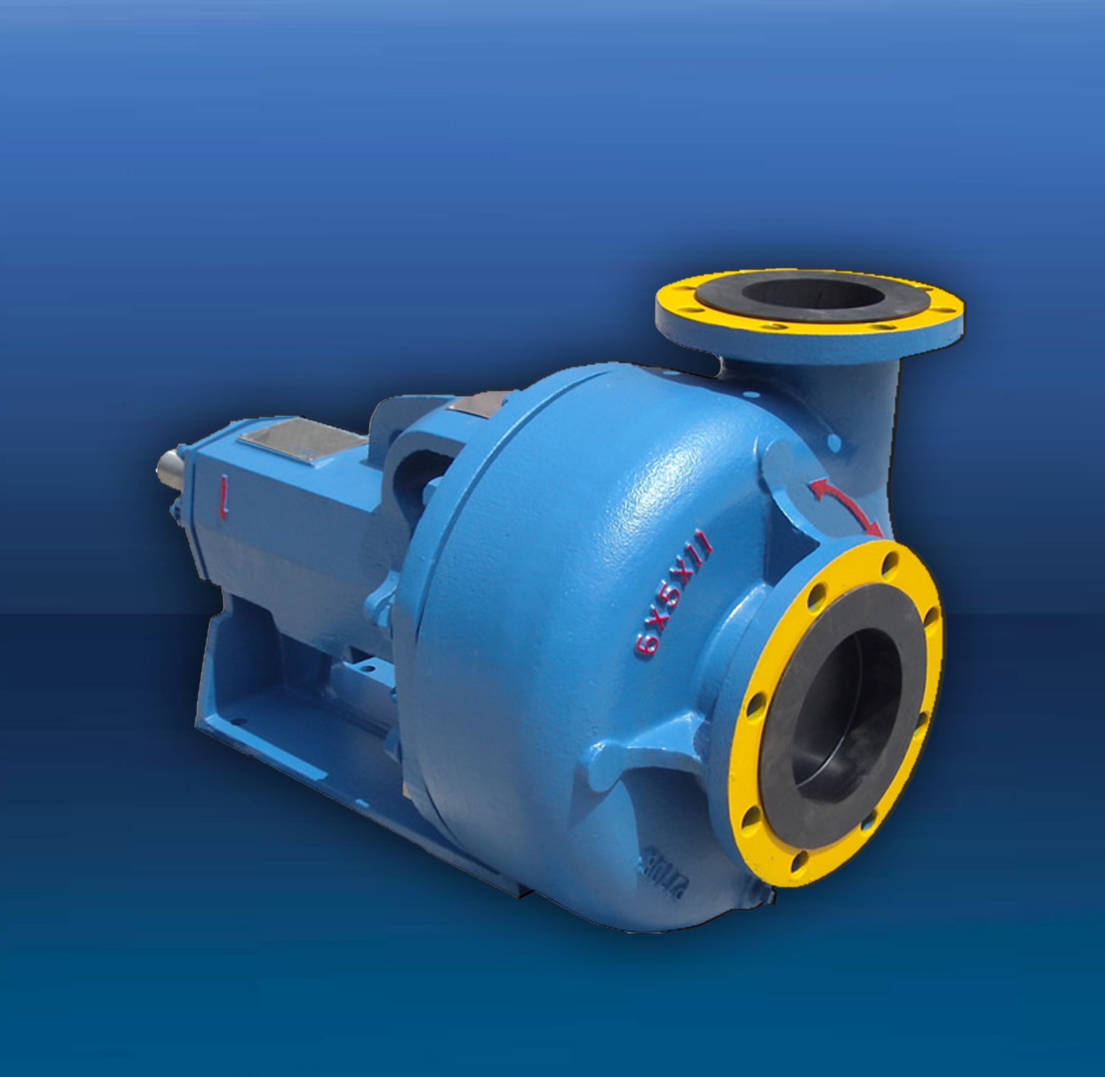
TTAAM-OM series centrifugal sand pump mainly supplies to solids control circulating system of the oilfield drill rig and can be used to provide drilling liquid with a certain discharge capacity and pressure to sand, desilter and mud mixer to assure these equipment work efficiently.
The TTAAM-OM8×6×11 centrifugal sand pump applies to under 3000-meter-long drilling Rigs and also can be used to supply mud to the triplex mud pump as a filling pump.
The pump is constituted of pump shell, impellers, bearing block, pump axle, bearing, shaft coupling, wearing plate, seal apparatus, oil seal, motor and base.
The array of ANSI centrifugal pumps are used for domestic and commercial purposes. The valuable features such as compact structure, low vibration, constant flow rate etc., make these pumps ideal to transport the liquid in different systems through the pipes. ANSI centrifugal pumps can also be used in various process applications. These pump have the capability to handle variety of challenging pumping applications. The durable and exclusive designs are carried out as per the industry standards and offers cost-effective solution.
Out of its huge repertoire of pumps & motors, ANSI centrifugal pumps are most popular among industries worldwide because of their dimensional interchangeability between its parts, easy to installation & maintenance and competitive cost.
These pumps are designed to handle non-viscous fluid from water to corrosive materials with high efficiency. ANSI centrifugal pumps are ideal for a number of different industries, including pulp and paper mills, chemical processing, food processing, refineries, and many other general services in manufacturing plants of all varieties.
The centrifugal pump is the most used pump type in the world. The principle is simple, well-described and thoroughly tested, and the pump is robust, effective and relatively inexpensive to produce.The ANSI pump that sets the industry standard for corrosive and abrasive process fluid applications. An increase in the fluid pressure from the pump inlet to its outlet is created when the pump is in operation. This pressure difference drives the fluid through the system or plant.
The centrifugal pump creates an increase in pressure by transferring mechanical energy from the motor to the fluid through the rotating impeller. The fluid flows from the inlet to the impeller centre and out along its blades. The centrifugal force hereby increases the fluid velocity and consequently also the kinetic energy is transformed to pressure.
A mud pump is a reciprocating piston/plunger pump designed to circulate drilling fluid under high pressure (up to 7,500 psi (52,000 kPa)) down the drill string and back up the annulus. A duplex mud pump is an important part of the equipment used for oil well drilling.
Duplex mud pumps (two piston/plungers) have generally been replaced by the triplex pump, but are still common in developing countries. Two later developments are the hex pump with six vertical pistons/plungers, and various quintuplex’s with five horizontal piston/plungers. The advantages that Duplex mud pumps have over convention triplex pumps is a lower mud noise which assists with better Measurement while drilling and Logging while drilling decoding.
Use duplex mud pumps to make sure that the circulation of the mud being drilled or the supply of liquid reaches the bottom of the well from the mud cleaning system. Despite being older technology than the triplex mud pump, the duplex mud pumps can use either electricity or diesel, and maintenance is easy due to their binocular floating seals and safety valves.
A mud pump is composed of many parts including mud pump liner, mud pump piston, modules, hydraulic seat pullers, and other parts. Parts of a mud pump:housing itself
Duplex pumps are used to provide a secondary means of fuel transfer in the event of a failure of the primary pump. Each pump in a duplex set is sized to meet the full flow requirements of the system. Pump controllers can be set for any of the following common operating modes:Lead / Lag (Primary / Secondary): The lead (primary) pump is selected by the user and the lag (secondary pump operates when a failure of the primary pump is detected.
Alternating: Operates per Lead / Lag (Primary / Secondary) except that the operating pump and lead / lag status alternate on consecutive starts. A variation is to alternate the pumps based on the operating time (hour meter) of the lead pump.

We provide a qualitative range of Mud Pumps, which are immensely used in construction, agriculture, waste water management and many other industries. These Mud Pumps are primarily reciprocating plunger devices designed for circulation of drilling fluid down the drill string and back up the annulus. Our range of pumps areread more... Brochure
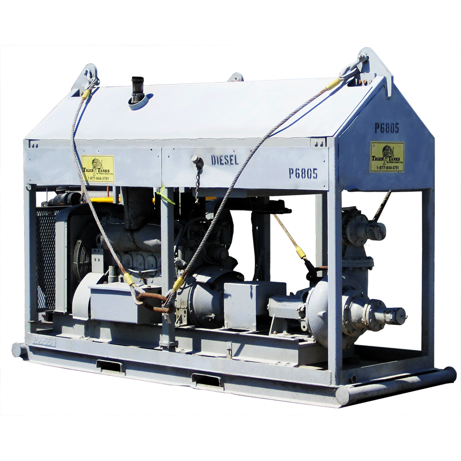
• Equipment – The 6 x 8 centrifugal pump is powered by a new John Deere 4.5 liter electric engine. It is also equipped with a 6” hopper, 3 mud guns, hydraulic shale shaker, and all necessary internal piping and manifolds

A part of National Oilwell Varco, the Mission line of centrifugal pumps are equipped with innovative features to match the demanding nature of routine, corrosive and abrasive applications. Because of the need for a low pressure mud system, Mission 1780 Type W centrifugal pumps were introduced in 1950s to replace duplex pumps. The aim was to apply a high quality centrifugal pump with concentric systems that allowed for abrasive fluids to be mixed and transferred thereby lowering the initial and maintenance costs of drilling. As a result, centrifugal pumps with low pressure mud systems such as Mission 1780 Type W became the industry standard.
As well depths increased, so was the need for heavier mud weights and centrifugal pumps that could withstand greater horsepower load. This led to the launch of Mission Magnum- a centrifugal pump.
The Magnum has an open impeller design that contains wide-tipped vanes and a more tangential circumference of the suction allowing the pump to create a smoother flow pattern when handling abrasive fluids. The Magnum is available in Magnachrome™, hard iron, stainless steel, and aluminum bronze fluid ends. The pumps can be unitized with electric motors, diesel engines, and hydraulic motors (horizontal, vertical, or close-coupled configuration).
Our pump engineering experts have the industry knowledge to gladly assist you with any questions, concerns, or inquiries you may have regarding the pumps & pump parts we distribute @ 800.560.7867.

A centrifugal pump is defined as a hydraulic machine that changes mechanical energy into hydraulic energy by the use of centrifugal force acting on the fluid. This is a machine that uses rotation to enforce velocity on a liquid, the velocity will then be converted into a flow. Every centrifugal pump is made up of mechanical components that make the operation of the pump possible.
This mechanical assembly involves the pump’s shaft mounted on bearings, the sealing mechanism that prevents the pump from leaking uncontrollably, structural components that are designed to handle the loads and stresses imposed on the pump during use, and also wear surfaces that permit the pump to be returned and returned to its original specifications.
It is the central part of the pump which rotates together with the impeller when connected. The shaft is linked to the prime mover in order to get the power. The shaft fits perfectly with the ball bearing.
It comprises an arrangement of backward curved vanes. It is mounted to an electric motor’s shaft. This is known as the rotating part of the centrifugal pump enclosed in a casing that is watertight. The impeller rotates and imparts velocity to a liquid.
This is a passage surrounding the impeller, which will be airtight. It is made in such a way that the water’s kinetic energy discharged at the outlet is changed to pressure energy before the water leaves the casing and is delivered into the delivery pipe. It works as a cover so that it protects the system. The casing transforms the velocity developed by the impeller into a stable flow. There are basically three types of casings in centrifugal pumps namely volute casing, vortex casing and casing with guide blades.
The suction pipe has two ends. The first end is connected to the pump’s inlet and one end is dipped into the water in a sump. At the suction pipes’ lower end, a foot valve is fitted. The valve only opens in an upward direction as it will be a one-way type. To prevent the entry of unknown and unwanted bodies into the suction pipe, a strainer is fitted at the end of the pipe.
When selecting materials for centrifugal pumps, there are factors that need to be considered. These are strength, resistance to abrasive wear, corrosion resistance, casting and machining performance, repair and welding performance, and costs.
Cast iron, cast steel, stainless steel, bronze, brass, carbon structural steel composite materials, alloy steel, and non-metallic materials are some of the materials used to make centrifugal pumps.
Cast iron – This is the most common material used to make centrifugal pumps. It provides high tensile strength and abrasion resistance correlated to high-pressure ratings. It is also durable.
Stainless steel - Austenitic stainless steel is the most common stainless steel that is used to make pumps. Stainless steel is usually used for chemical pumps as it is corrosion resistant. Its tensile strength is remarkably high.
Non-metallic materials – This material in pumps is mainly used for sealing purposes for example polytetrafluoroethylene, rubber, nitrile rubber, and fluorine. Polytetrafluoroethylene has excellent high temperature resistance and corrosion resistance. Is used for static seals of mechanical seals and chemical pump gaskets. It is advisable to use almost all chemical media within 250°C.
Bronze – Can be used for the body of the pump. It helps the sealing of the pump body. For larger centrifugal pumps, tin bronze is used as a material for the body. Although nickel aluminum bronze is corrosion resistant and has the best mechanical properties it is expensive and incompetent.
Composite materials - to improve the chemical resistance of the pump, a lining can be installed in the volute. The materials used for the lining can be rubber. Graphite monolithic ceramic and pumps are used in particular corrosive liquids, like hydrofluoric acid which is used in the pulp and paper industry and metal finishing industry. Composite materials are also used to make pump bodies.
Chemical compatibility - Pump parts that will be in contact with the pumped media can be made from chemically compatible materials that will not be contaminated or result in excessive corrosion or contamination. Consulting a metallurgist for proper metal selection is advised when dealing with corrosive media.
Wear - Pumps that handle abrasives generally need materials with good wearing capabilities. Chemically resistant and hard surface materials are often incompatible. The housing and base materials should be of the right strength and also should be able to hold up against the conditions and environment being operated from.
These pumps operate 12 V DC, with a maximum flow of 330 GPH. It consists of alligator clips, a battery cable, and an on/off switch for ease when operating. The lowest height of water being pumped out can be 1/8 inches with the suction strainer, and the largest height of water being lifted is 40 feet. 3/4 inches garden hose adapter at both outlet and inlets, 6 feet suction hose, gasket for replacement, and an extra impeller. It can be portable due to its lightweight. In that case, a carrying handle can be attached to the body for convenient use.
Chemical pumps are designed specifically for use in pumping chemicals that are resistant to corrosive materials, which makes it suitable for handling corrosive and abrasive industrial liquids such as paint, fuel, solvent, bleach, and many others. A pump that contradicts the chemical can result in brittleness or dissolving, swelling, and ultimately it will leak and fail. Special consideration needs to be given to the materials of a chemical transfer pump, along with the concentration and temperature of the fluid being handled. Whenever there is required a chemical dosing pump, one for tank to tank transfer or a barrel emptying pump, the pump can be tested.
In radial centrifugal pumps, the fluid comes out of the impeller after rotating for 90 degrees relative to the suction. Many centrifugal pumps are found in this category. Fluid enters through the horizontal suction flange and leaves through a vertical outflow flange. The discharge will be perpendicular to the pump’s shaft. This design is commonly used when there is a flow limitation and a need to raise the discharge pressure. Thus, radial design is a low flow rate and a high-pressure pump. Most pumps that are used in the gas and oil industries fall into this category.
In an axial flow centrifugal pump, the fluid can move parallel to the shaft. This procedure is the same as the working of a propellant. The most important application of this pump is when there is a huge flow rate and very little pressure head. For instance, they are common in water circulation pumps and dewatering pumps.
As the name states, in a mixed flow centrifugal pump, the fluid flow mixes both axial and radial properties. That is a trade-off between radial and axial pumps. Mixed pumps operate at a much larger flow rate with a decent increase in the head.
In a single-suction centrifugal pump, the flow of the fluid is directed into the inlet, and the rest of the liquid immediately flows into the impeller eye, which is the inlet of the impeller. By the time when the water leaves the impeller, pressure is produced by the centrifugal force.
Single-suction will be inadequate when the flow rate is too high. In such a case, double suction centrifugal pumps are utilized. The pump’s impeller is engineered so that the fluid enters from all sides as compared to the single side in a normal case. Nevertheless, the name “double suction” should not be confusing. Even in the double suction pump design, there is only a single flange discharge and suction. The difference is in the design of the casing and impeller.
In centrifugal pumps that have a single volute casing, the flow is discharged from the impeller and goes into one volute, which winds completely around the impeller. This single volute casing has one cut-water that transports the fluid flow towards the pump’s outlet. Most of the centrifugal pumps in the refinery are of single volute types.
These pumps are portable pumps and are generally for dewatering applications. They are planned to pump large amounts of water that contains soft and hard solids such as mud, twigs, leaves, sand, and sludge. Most trash pumps are heavy-duty, portable centrifugal pumps that have larger discharge openings and deeper impeller vanes than other pumps. Trash pumps are capable of processing materials with some suspended particulates that can clog other centrifugal pumps and can move hundreds better yet thousands of gallons per minute. The materials that enter the pump are not grounded in the trash pump. They are designed to have a large discharge opening, pump housing, and deep impellers veins. The pumps can be made from cast iron, steel, aluminum, and stainless steel. Most of these pumps have roll cages.
Semi-trash pumps are types of trash pumps that have a smaller opening. They are not conceived to handle large solids or high solid concentrations. As a result, regular trash pumps are better suited for uses that need rigorous pumping of solid-laden slurries or water.
Syringe pumps are used for dealing with materials that require exact flow amounts at exact time intervals. Infusion pumps process fluid at highly controlled pressures and withdrawal pumps remove the fluid, these are the two types of syringe pumps.
Sanitary trash pumps are pumps used in applications progressive cavity trash pumps that need high levels of sanitation such as in breweries, food, and biotech companies. This type of pump is also able to move meters and slurry solutions.
Progressive cavity pumps are used for moving fluids and slurries with suspended solids. The fluids are suctioned from one side of the pump discharged from the other and then to a storage tank or through a pipeline. Cavity pumps can suitably transfer slower-moving viscous fluids and materials from these pumps and can be moved in a continuous flow.
Positive displacement pumps use pistons, diaphragms, gears, and other devices to pump fluids through. They can also be moved by a vacuum created when the fluid is pumped into a fixed cavity and then pumped out again, creating a vacuum that sucks in other fluids. Displacement pumps are the best when it comes to viscous liquids that are subjected to great pressure.
They are also known as deep well turbine pumps. These are vertical axis or mixed flow centrifugal pumps which include stages of stationary bowls and rotating impellers to process the guide vanes. Vertical pumps are used whenever the level of water pumping is below the volute centrifugal pump limits. Vertical pumps are costly and are more complicated to refurbish and fit. The design of the pressure head mainly depends on the impeller’s length as well as on the speed of its rotation. The pressure head designed with just one impeller is not that suitable.
The well pump is the heart of the water well system. They pump water upward and into the household or designated water system. Jet pumps and submersible pumps are the most popular pumps used nowadays. Both pumps depend on the centrifugal force for them to force water upward. Spinning rotors, also referred to as impellers, create a vacuum that forces the water upward through the well casing and into the distribution system. The type of suitable well pump required for a well system should depend on the amount of water required for each household and on the depth of the well.
Jet pumps are placed on top of the ground and lift water from the ground through a suction pipe, creating a vacuum with an impeller. The impeller drives water through a small nozzle. There is a need to first prime the jet pumps with flowing water as it pumps water. Shallow well jet pumps are utilized in wells with a depth of 25 feet while on the other hand, deep well jet pumps typically cover a depth of 150 feet.
Submersible well pumps have a much wider range in-depth and can be used in wells as shallow as 25 feet and as deep as 400 feet. As the name suggests, submersible well pumps are submerged deep in the well just beneath the water level. The majority of its energy is dedicated to pushing water upwards unlike sucking water from above as with the jet well pumps.
Submersibles are cylindrical in shape, and they consist of a pump motor and several impellers for driving water up the pump and into the drop pipe. Because of their durability, efficiency, and versatility in well depth, the majority of modern well systems use submersible pumps over some other pumps.
The centrifugal pumps are appropriate for large discharges but with a small head. Whereas reciprocating pumps do the opposite for less discharge with a high head..
Centrifugal pumps need a heavy foundation and more floor space whilst the reciprocating pump requires less floor space with a light and simple foundation.
Many industries (manufacturing, industrial, chemicals, food production, pharmaceutical, and aerospace) – use the pumps for the purposes of refrigerants and cryogenics..
They can be used as metering pumps that can pump precise volumes of liquid for treating water for example wastewater, drinking water, swimming pool water, and boiler water..
They are also used in process applications where metering of fluids is needed, where extreme high pressures are required, or where the sealless nature of the pump type is beneficial..
Corrosion Resistance – the pumps allow processors and manufacturers to transfer different types of fluids, even those that can quickly corrode the other pumps. The pumps even when used extremely well can offer a long service life. The pumps are able to withstand corrosive materials.
Energy Efficiency - Centrifugal chemical pumps rank high in energy efficiency in comparison to all the other pumping technologies. Their efficiency reduces costs both over the life span or in the short term of each unit.
Proven Reliability - Centrifugal chemical pumps are the best choice when reliability is important. The pump should be evaluated on the construction and design and features in order to ensure the specified pump will be durable enough to operate in extreme conditions.
Low Maintenance -Due to the long life spans, some pumps may need to be frequently routine maintained, which can make them costly to operate. However, centrifugal chemical pumps have low routine maintenance requirements.
Application Versatility- The same pump configuration is unsuitable for every application. With centrifugal chemical pumps, different configurations are there to provide solutions for multiple uses.
The absence of drive seals eliminates the risk of a leak. This means that hazardous liquids can be pumped efficiently without any spillages. Eliminating the drive seals is a way of getting rid of leaks, wear, friction loss, and noise and provides separation of fluid from the pump drive.
Lack of prime— In order to operate properly, centrifugal pumps must be filled with the fluid that needs to be pumped. If the pump casing is filled with gasses or vapor, the pump impeller becomes gas-bound and can stop pumping at all.
Liquids that contain ferrous particles can be problematic when a centrifugal magnetic drive pump is used. This is a result of the particles collecting on the impeller magnet, and as time passes it can cause the pump to stop working. Some of the energy is lost in the coupling. This is basically due to some magnetic resistance. The coupling may slip if unexpectedly heavy loads occur.
Centrifugal pumps use rotation to move water instead of suction and therefore have little or no suction power. This proves that a centrifugal pump must be primed or put underwater before it can move water or other liquids.
Determine the maintenance frequency with which the pumps should be checked and repaired. A certain time frame should be set to check the pump and verify if it is still working properly or as required.
Inspection and replacement of mechanical parts should be done regularly. The inspection can be a quarterly inspection, routine inspection or annual inspection. This inspection involves steps such as checking pipe lines for leakages, checking bearing temperature, increased vibration, unnatural and uneven noise, stuffing box, mechanical seal, discharge pressure and operating current. For annual inspection, check if all mount points are secure, clean filter, inspect pump flange for leaks, replace the mechanical seal, inspect coupling, replace lubricating oil and check shaft alignment.
Changing the pump"s lube oil is part and parcel of the annual inspection routine or the scheduled maintenance. It is essential to prevent bearing damage. One should remember to follow the manufacturer’s guidelines when it comes time to lubricate the motor. Be careful not to over or under lubricate the system. The damage to the pump may be greater in case of over greasing than in under greasing, to prevent this, the manufacturer’s instructions must be followed. There is a need to frequently lube if the pump is used frequently on a daily basis.
A centrifugal pump is a machine that changes kinetic energy into the fluid’s pressure head. The external power from a diesel generator or electric motor then turns the pump impeller. Under the influence of the centrifugal force, the fluid enters the impeller reaching its tip and leaving the volute casing. There are many types of centrifugal pumps for example chemical pumps, vertical pumps, and trash pumps to mention only a few. They can be classified according to flow type), based on the number of stages (single stage and multi-stage pumps), and also on the type of volute (single and double volute).
Maintaining the pump is easy; most of the measures are given in the manufacturer’s guide. If used and maintained properly the centrifugal pumps can last long and are less costly. Choose a pump that is compatible with what needs to be used for example when pumping hazardous chemicals, a chemical pump is advised.

Selecting the right pump type can be challenging. Azcue Pumps has a variety of pump types to choose from including variations in orientation, priming capabilities, motor configuration, suction method to name a few. In addition to the variety in pump capabilities, Azcue Pumps offers different metal construction to fit your needs. Browse the selection of pumps below or contact usand let one of our experts assist you in finding the right pump for your needs.

Centrifugal pumps are used to transport fluids by the conversion of rotational kinetic energy to the hydrodynamic energy of the fluid flow. The rotational energy typically comes from an engine or electric motor. They are a sub-class of dynamic axisymmetric work-absorbing turbomachinery.volute chamber (casing), from which it exits.
Common uses include water, sewage, agriculture, petroleum, and petrochemical pumping. Centrifugal pumps are often chosen for their high flow rate capabilities, abrasive solution compatibility, mixing potential, as well as their relatively simple engineering.centrifugal fan is commonly used to implement an air handling unit or vacuum cleaner. The reverse function of the centrifugal pump is a water turbine converting potential energy of water pressure into mechanical rotational energy.
According to Reti, the first machine that could be characterized as a centrifugal pump was a mud lifting machine which appeared as early as 1475 in a treatise by the Italian Renaissance engineer Francesco di Giorgio Martini.Denis Papin built one using straight vanes. The curved vane was introduced by British inventor John Appold in 1851.
Like most pumps, a centrifugal pump converts rotational energy, often from a motor, to energy in a moving fluid. A portion of the energy goes into kinetic energy of the fluid. Fluid enters axially through eye of the casing, is caught up in the impeller blades, and is whirled tangentially and radially outward until it leaves through all circumferential parts of the impeller into the diffuser part of the casing. The fluid gains both velocity and pressure while passing through the impeller. The doughnut-shaped diffuser, or scroll, section of the casing decelerates the flow and further increases the pressure.
The color triangle formed by velocity vector u,c,w called "velocity triangle". This rule was helpful to detail Eq.(1) become Eq.(2) and wide explained how the pump works.
Vertical centrifugal pumps are also referred to as cantilever pumps. They utilize a unique shaft and bearing support configuration that allows the volute to hang in the sump while the bearings are outside the sump. This style of pump uses no stuffing box to seal the shaft but instead utilizes a "throttle bushing". A common application for this style of pump is in a parts washer.
In the mineral industry, or in the extraction of oilsand, froth is generated to separate the rich minerals or bitumen from the sand and clays. Froth contains air that tends to block conventional pumps and cause loss of prime. Over history, industry has developed different ways to deal with this problem. In the pulp and paper industry holes are drilled in the impeller. Air escapes to the back of the impeller and a special expeller discharges the air back to the suction tank. The impeller may also feature special small vanes between the primary vanes called split vanes or secondary vanes. Some pumps may feature a large eye, an inducer or recirculation of pressurized froth from the pump discharge back to the suction to break the bubbles.
A centrifugal pump containing two or more impellers is called a multistage centrifugal pump. The impellers may be mounted on the same shaft or on different shafts. At each stage, the fluid is directed to the center before making its way to the discharge on the outer diameter.
A common application of the multistage centrifugal pump is the boiler feedwater pump. For example, a 350 MW unit would require two feedpumps in parallel. Each feedpump is a multistage centrifugal pump producing 150 L/s at 21 MPa.
The energy usage in a pumping installation is determined by the flow required, the height lifted and the length and friction characteristics of the pipeline.
An oilfield solids control system needs many centrifugal pumps to sit on or in mud tanks. The types of centrifugal pumps used are sand pumps, submersible slurry pumps, shear pumps, and charging pumps. They are defined for their different functions, but their working principle is the same.
Magnetically coupled pumps, or magnetic drive pumps, vary from the traditional pumping style, as the motor is coupled to the pump by magnetic means rather than by a direct mechanical shaft. The pump works via a drive magnet, "driving" the pump rotor, which is magnetically coupled to the primary shaft driven by the motor.gland is needed. There is no risk of leakage, unless the casing is broken. Since the pump shaft is not supported by bearings outside the pump"s housing, support inside the pump is provided by bushings. The pump size of a magnetic drive pumps can go from few watts of power to a giant 1 MW.
The process of filling the pump with liquid is called priming. All centrifugal pumps require liquid in the liquid casing to prime. If the pump casing becomes filled with vapors or gases, the pump impeller becomes gas-bound and incapable of pumping.
In normal conditions, common centrifugal pumps are unable to evacuate the air from an inlet line leading to a fluid level whose geodetic altitude is below that of the pump. Self-priming pumps have to be capable of evacuating air (see Venting) from the pump suction line without any external auxiliary devices.
Centrifugal pumps with an internal suction stage such as water-jet pumps or side-channel pumps are also classified as self-priming pumps.American Marsh in 1938.
Centrifugal pumps that are not designed with an internal or external self-priming stage can only start to pump the fluid after the pump has initially been primed with the fluid. Sturdier but slower, their impellers are designed to move liquid, which is far denser than air, leaving them unable to operate when air is present.check valve or a vent valve must be fitted to prevent any siphon action and ensure that the fluid remains in the casing when the pump has been stopped. In self-priming centrifugal pumps with a separation chamber the fluid pumped and the entrained air bubbles are pumped into the separation chamber by the impeller action.
The air escapes through the pump discharge nozzle whilst the fluid drops back down and is once more entrained by the impeller. The suction line is thus continuously evacuated. The design required for such a self-priming feature has an adverse effect on pump efficiency. Also, the dimensions of the separating chamber are relatively large. For these reasons this solution is only adopted for small pumps, e.g. garden pumps. More frequently used types of self-priming pumps are side-channel and water-ring pumps.
Another type of self-priming pump is a centrifugal pump with two casing chambers and an open impeller. This design is not only used for its self-priming capabilities but also for its degassing effects when pumping twophase mixtures (air/gas and liquid) for a short time in process engineering or when handling polluted fluids, for example, when draining water from construction pits.This pump type operates without a foot valve and without an evacuation device on the suction side. The pump has to be primed with the fluid to be handled prior to commissioning. Two-phase mixture is pumped until the suction line has been evacuated and the fluid level has been pushed into the front suction intake chamber by atmospheric pressure. During normal pumping operation this pump works like an ordinary centrifugal pump.
Baha Abulnaga (2004). Pumping Oilsand Froth (PDF). 21st International Pump Users Symposium, Baltimore, Maryland. Published by Texas A&M University, Texas, USA. Archived from the original (PDF) on 2014-08-11. Retrieved 2012-10-28.
Moniz, Paresh Girdhar, Octo (2004). Practical centrifugal pumps design, operation and maintenance (1. publ. ed.). Oxford: Newnes. p. 13. ISBN 0750662735. Retrieved 3 April 2015.

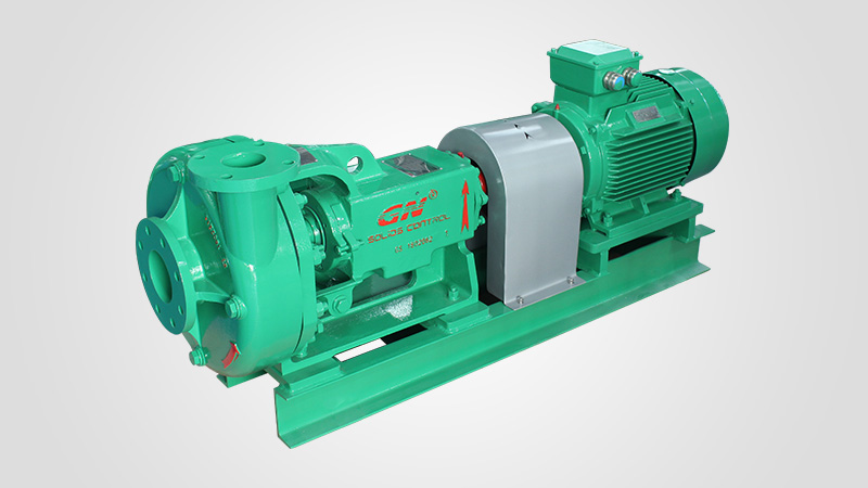
GNSB Series Centrifugal Mud Pump is designed to transfer industry slurry, waste water with solids less than 2mm. It’s widely used for drilling industry, construction mud transfer, environmental waste fluids transfer as well as mining slurry transfer industry. GNSB Centrifugal Mud Pumps have been field proven to meet the standards for rugged and demanding applications. The pump is capable to be used for high volume, high temperature slurry and pumping high abrasive, high viscosity fluids.
Fully casting pump skid instead of welding to provide stable supporting for the pump and motor, in a result to improve the operation life of the coupling and all bearings.
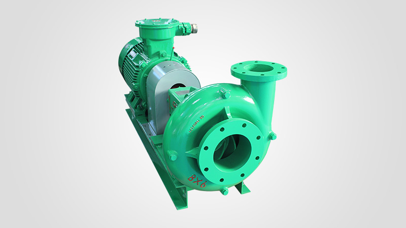
GN Separation and Conveying Equipment company manufacture separation equipment and conveying equipment as well as the transfer pumps for the industry process application. This allows GN to be able to provide full package solution to our clients for different applications. Both GNSB transfer Centrifugal Mud Pump and separation equipment are widely used for following industry.


 8613371530291