
mud pump condition monitoring price
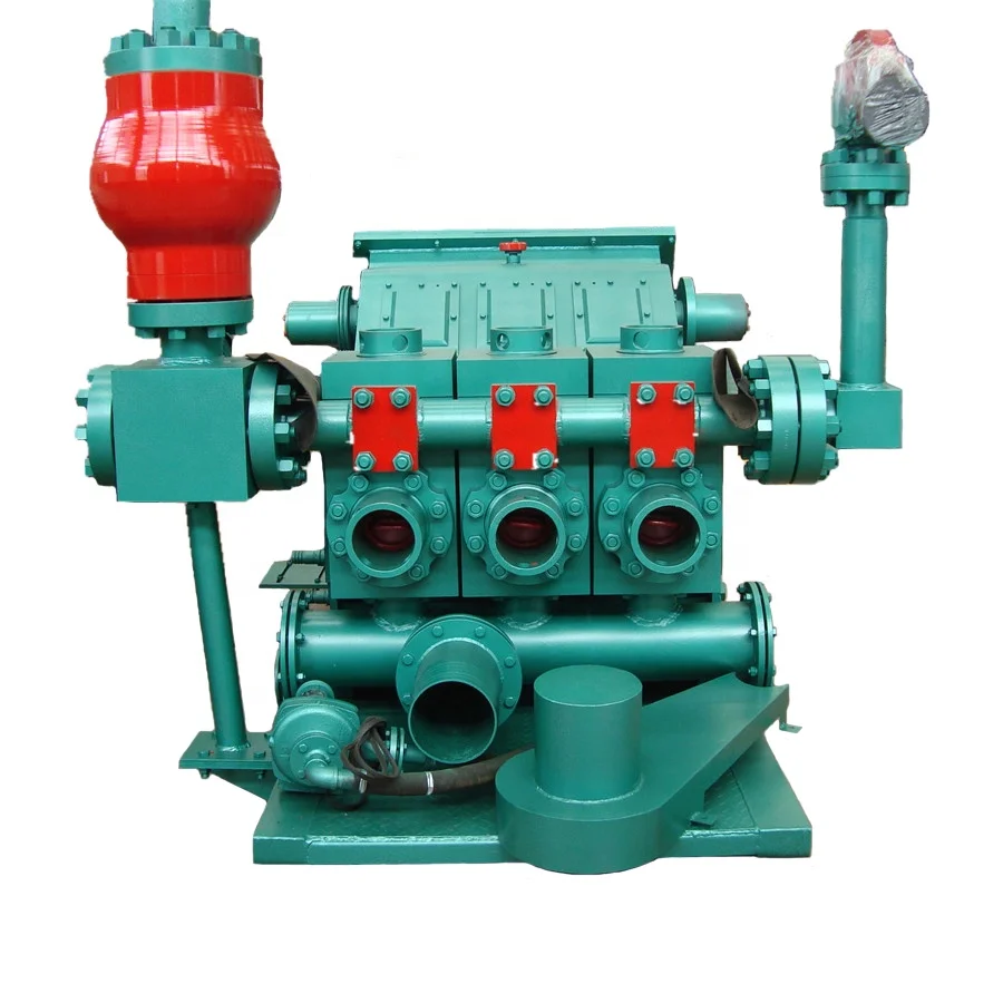
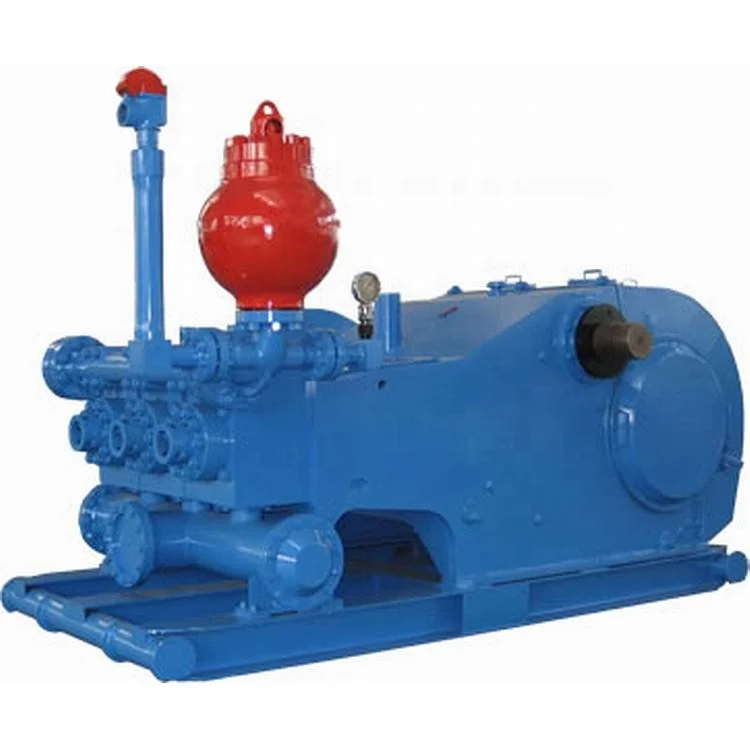
The 2,200-hp mud pump for offshore applications is a single-acting reciprocating triplex mud pump designed for high fluid flow rates, even at low operating speeds, and with a long stroke design. These features reduce the number of load reversals in critical components and increase the life of fluid end parts.
The pump’s critical components are strategically placed to make maintenance and inspection far easier and safer. The two-piece, quick-release piston rod lets you remove the piston without disturbing the liner, minimizing downtime when you’re replacing fluid parts.

Power and high pressure mud management system is a core function in any oil field operation. Consequential cost of any failure results in an exponential manner through out the chain of drilling activity. Under an open pay zone condition, the effect would compound leading to complications in oil recovery, where such far flung effects are involved in terms of cost of failure, the demand of availability and reliability is not the final requirement of a maintenance manager. Monitoring the trend of all the achievements and failure also becomes an important activity to device a means for all the time injection of dependability. In this trend analysis the diverse and concurrent behavior of different group of equipments are to be monitored in a manageable manner for setting up the hypothesis structures to derive fairly repeatable and accurate predictions.

Unexpected failure of mud pumps during drilling operations can result in non-productive time (NPT) and increase well construction cost. Several prior studies and implementations of condition-based maintenance (CBM) systems for mud pumps have failed to provide a generalized solution for the variety of pump types encountered in the field, in particular by failing to detect damage early enough to mitigate NPT. Our research is aimed at improving upon this situation by developing a practical, generally-applicable CBM system for mud pumps.
In the study reported here, a laboratory test bed with a triplex mud pump was used to collect data to test a new approach to mud pump CBM. Artificial damage was introduced to the two most frequently replaced parts of the pump, i.e., the valve and piston. An accelerometer and an acoustic emission (AE) sensor were used to collect experimental data. Based on this data, an anomaly detection algorithm was constructed using a one-class support vector machine (OC-SVM) to pin-point the early onset of mud pump failure. The CBM methodology thus developed does not require prior knowledge (data) of the mud pump itself or of the failures of its components. This is key to it being more widely deployable.
The trained machine-learning algorithm in the test setup provided an accuracy greater than 90% in detecting the damaged state of the valve and piston. Only the characterization of the normal (i.e., non-damaged) state data was required to train the model. This is a very important result, because it implies that the sensors can be deployed directly onto mud pumps in the field – and additionally, that the first few hours of operation are sufficient to benchmark normal operating conditions. Also, it was observed that a multi-sensor approach improved the accuracy of detection of both the valve and piston damage. The system is able to detect early-stage damage by combining the cumulative sum control chart (CUSUM) with the damage index developed in this project.
This work is the first attempt at applying semi-supervised learning for CBM of mud pumps. The approach is applicable for field use with very little or no prior damage data, and in various working conditions. Additionally, the system can be universally deployed on any triplex pump and efficiently uses the data collected in the first few hours of operation as a baseline. Consequently, the practicality and scalability of the system are high. It is expected to enable the timely maintenance of critical rig equipment before catastrophic damage, failure and associated downtime occurs. The system has been deemed promising enough to be field-trialed, and is currently being trialed on rigs in North America.

A mud pump is a reciprocating piston/plunger device designed to circulate drilling fluid under high pressure down the drill string and back up the annulus.
Mud pumps come in a variety of sizes and configurations, but for the typical petroleum drilling rig, the triplex (three piston/plunger) mud pump is the pump of choice. Duplex mud pumps (two piston/plungers) have generally been replaced by the triplex pump, but are still common in developing countries. A later development is the hex pump with six pistons/plungers.
The normal mud pump consists of two main sub-assemblies—the fluid end and the power end. The fluid end produces the pumping process with valves, pistons, and liners. Because these components are high-wear items, modern pumps are designed to allow for quick replacement.
To reduce severe vibration caused by the pumping process, mud pumps incorporate both suction and discharge pulsation dampeners. These are connected to the inlet and outlet of the fluid end.
The number of mud pumps varies per drilling rig depending on the size of the drilling rig. The larger the rig the more mud pumps that will be needed. The mud pumps are considered vital to the operation of the drilling rig. If the mud pumps fail it affects production and can be very costly to repair due to the downtime in production.
To avoid any failures of the pumps, an online monitoring system was selected to collect and transmit vibration data back to a software system for analysis. This online monitoring and diagnostic system can also be expanded by a series of program modules (MUXs) that are specific to the application:

Compounding this growth are aging plants with critical equipment at the end of its life—increasing demands for reliability—and an aging workforce reaching retirement in the next few years. All these factors exponentially increase the need for effective and automatic knowledge transfer, training and new approaches to the maintenance of power generation assets. Today, the process of condition monitoring is largely conducted manually, meaning technicians and operators monitor equipment on their walking rounds or tours within a plant (Figure 1). This includes capturing data logs, inspections and assessments, performance testing, maintenance, and capturing history and events. In addition, this provides limited access to equipment condition monitoring.
difference between generating a profit or a loss. However, increased inspection through online monitoring and data collection can mitigate these risks.
To optimize machine maintenance and, therefore, machine reliability and use, monitoring health indicators such as mechanical vibration, temperature and power factor is a widely accepted practice. However, the cost of cabling the sensor and data acquisition hardware to the control room has impeded the use of monitoring for reliability and usage improvements. Today, with the use of wireless vibration and power monitoring devices, reliability engineers can overcome historical cost barriers.
Power generation providers are taking advantage of the cost effectiveness of wireless devices to add low-cost sensors to equipment. Without the need to connect wires to transfer data, reliability engineers can expand instrumentation beyond critical assets and communicate condition monitoring data for many assets across systems.
Online machine monitoring monitors equipment as it runs. Data are acquired by an embedded device and are transmitted to a main server for data analysis and maintenance scheduling.
Most machine condition monitoring sensors require some form of signal conditioning to optimally function, such as excitation power to an accelerometer. Filtering on the signal to reduce line noise and unwanted frequency ranges is also common.
Implementing an asset monitoring system provides other advantages in addition to cost savings. For example, organizations can plan replacement parts inventory to meet maintenance demands by ensuring that the correct parts are available at the right location as needed, ensuring better fleet management. Also, with a longer maintenance cycle based on machine health, a longer equipment life span can be expected.
Another benefit is the production assurance that an asset monitoring system provides. The system can identify developing faults with enough lead time to properly schedule maintenance during planned downtimes, avoiding unnecessary and expensive site shutdowns.
Most important, by monitoring the machine and its performance parameters, the condition monitoring system can signal a system shutdown before serious injury or other harm occurs.
With the advent of advanced maintenance methods, industrial machinery and asset monitoring systems continue to become more sophisticated. As a result, the requirements for such systems are constantly evolving, which creates new challenges for selecting the appropriate instrumentation for asset monitoring.
In power plants, for example, plant operations personnel access the business network of the plant using mobile devices such as tablets and cell phone technologies. With an industrial wireless network available within the plant, personnel can access email, internal documents and drawings, and other resources that they may need while performing operations in the field. Incorporating Wi-Fi access points with process plants, including power generation and oil and gas plants, offers a clear business benefit beyond condition monitoring. However, transmission of vibration time waveforms may use all the available bandwidth even with an 802.11n implementation.
To mitigate bandwidth issues with Wi-Fi, or any other radio technologies, a report featuring exception or decision-based data recording with store and forward capabilities is most appropriate (see Figure 2). Decision-based data recording devices are often referred to as a Data Acquisition and Analysis Node (DAAN). When the DAAN can evaluate all sensor values for exception and log sensor values locally, two main benefits are achieved. First, when reporting by exception sensory, data are filtered for changes, exceptions or required periodic reports. Second, recording sensor data and condition indicators is possible even when the wireless communications network is not available or experiences bandwidth degradation.
By leveraging a DAAN to filter data and to store sensor data and condition indicators locally, engineers can use the Wi-Fi networks in both process and manufacturing facilities. This makes deploying condition monitoring DAANs possible without the need to deploy communications cabling. Even with these capabilities, plant motors and equipment can cause communication noise. Both Cisco and N-Tron recommend and offer wireless network surveys to help determine the best wireless networking topology for individual applications.
Part Two of this series, which will appear in the December 2013 issue, will address the importance of reducing human exposure to hazardous environments—such as manual maintenance inspections on industrial mud pumps—during onshore and offshore drilling. It will discuss the hardware and software tools used to deploy an embedded system to monitor and analyze mud pump vibrations.
The ballasted track currently remains one of the few leading types of railway track structures due to the advantages in construction and maintenance [1,2]. However, the particulate nature of ballast particles often leads to performance degradation of ballasted trackbed. For example, the abrasion and breakage of ballast particles intensify with increasing axle load and train speed, thus causing the unfavorable densification, fouling, and clogging (i.e., reduced drainability) problems in ballasted tracked [3,4,5]; consequently, mud pumps, among other commonly observed track problems, can be prompted within such fouled ballasted trackbed [6,7]. Mud pumps could seriously degrade track stiffness and thus endanger operational safety of railway trains [8,9,10]. Traditional manual inspection and detection of mud pumps and other track problems are often labor-intensive, time-consuming, and subjective in nature; therefore, it becomes indispensable to develop automated, intelligent, and accurate means for the early-age diagnosis and detection of mud-pumping risks in ballasted trackbed so that remedial maintenance measures can be timely taken according to real-time health condition rather than the fixed schedules.
The root cause of mud-pumping fault has remained a widely-studied but challenging topic. Tadatoshi [11] proposed a suction-driven model and showed that the main cause of mud pumps is the intrusion of fine particles from the subgrade generated by the suction of ballast bed during the loading and unloading cycles. Raymond [12] found that the freeze-thaw cycles can cause fine-grained materials to pump out of the ballasted trackbed in winters according to a field performance investigation of the North American railway geotextiles. Duong et al. [13,14] believed that the interlayer materials between the subgrade and the ballasted trackbed were mainly generated by broken ballast particles, which then penetrated into the subgrade surface. The formerly Transportation Technology Center, Inc. (TTCI) established a field-testing zone to further study mud pumps [10,15,16,17]. Despite a considerable number of research studies have been carried out to explore the mechanisms of mud pumping fault, there still lacks radical countermeasures to prevent and control it in railway engineering practices.
The accurate early-age diagnosis and detection of mud pumps are the key step on which timely and effective prevention and control measures depend. The late-stage mud-pumping fault manifested on the surface of ballasted tracked is relatively easy to detect through routine labor-intensive methods; however, it is quite challenging to directly identify the early-age mud-pumping problem initiated inside the thick ballasted trackbed. The ground penetrating radar (GPR) technology has been widely applied in the non-destructive detection of structural faults in railway ballasted trackbed and subgrade [10,18,19,20]. Hugenschmidt [21] successfully applied GPR in the detection of railway subgrade problems for the first time in 1998. Since then, many countries including China have conducted related field and laboratory studies in this field [22,23]. Trong Vinh Duong et al. [13] carried out physical model tests and analyzed the influencing factors of the mud-pumping problem occurring in the interlayer between the ballast bed and underlying subgrade, including particle size distribution, moisture content, pore water pressure, hydraulic conductivity, etc. Kuo et al. [24] developed a characterized grid method and a scoring method to assess the mud-pumping distribution with an accuracy rate of 80%. Although the GPR technology has been reported to successfully detect visible or hidden mud-pumping problems in ballasted railway tracks [21], the accuracy and reliability of different GPR equipment and supporting post-processing software programs still vary considerably, not to mention the fact that they are highly costly and unaffordable for routine applications. In addition to GPR, other techniques have also been widely used for non-destructive detection of railway track foundation problems in recent years, such as the digital image correlation (DIC) [25,26,27], Interferometric Synthetic Aperture Radar (InSAR) [25], impact-echo method (IEM) [28], and synthetic aperture focusing technology (SAFT) [29,30]. However, these methods all require costly equipment and/or highly specialized skills that railway engineering practitioners usually lack. Therefore, to diagnose the in-service health condition and detect invisible problems of the ballasted trackbed accurately and reliably, it becomes imperative to explore automated, intelligent, and universally applicable methods in lieu of traditional ones.
The occurrence of mud pumps could cause uneven (or differential) rail track settlement and increasing track irregularities [31,32,33]. The existence of track irregularities could not only compromise the operational safety of heavy-haul trains but also degrade track substructures [34,35,36]. Li et al. [37,38] proposed a data-driven method for infrastructure deformation identification based on the characteristics of track geometry data, as well as a spatio-temporal identification model for identifying high-speed railway infrastructure deformation by using four years of track geometry data. Li et al. [39] analyzed the time and frequency characteristics of track geometry irregularity signals at the locations of mud pumps and used a multi-scale signal decomposition method to extract defect-sensitive features and then realize automatic detection of mud pumping problems. The nearly continuous and real-time track health monitoring of the entire rail networks could be possibly accomplished in a timely and cost-efficient manner by mounting robust sensors on in-service trains. For example, the problematic sections of railway track sub-structures were reportedly detected by using the vertical acceleration responses of a moving train [40]. Zeng et al. [41] proposed a data-driven approach for identifying mud pumps in the railway track substructure based on vibrational acceleration responses and Long Short-Term Memory (LSTM) artificial neural networks. The vibrational responses of ballastless slab tracks were also compared to detect the locations of mud pumps and study the feasibility of technical countermeasures to rectify and control the mud-pumping damage [42]. Therefore, analyzing the vibrational responses of the ballasted trackbed appears to be potentially helpful and promising for intelligent detection of mud-pumping problems in railway tracks.
Particle movement is a meso-scale manifestation of inter-particle contact behavior of ballast assemblies within the ballast bed; therefore, investigating the meso-scale movement characteristics of ballast particles may emerge as a promising, effective alternative to diagnose and identify the mud-pumping problem of ballasted tracked. The use of motion sensors (termed as “SmartRocks”) has been reported in the literature to directly capture real-time movement of ballast particles and then evaluate the field performance of ballasted trackbed under different in-service conditions [43,44,45,46,47]. The applications of such so-called SmartRock sensors in effective and accurate measurements of the vibrational responses of unbound aggregate particles including railroad ballasts were demonstrated in laboratory scaled model tests and triaxial tests [43,48,49,50]. Liu et al. [51] compared the ballast particle motion data measured by SmartRock sensors against those simulated by the discrete element method (DEM) model. Preliminary studies [52,53] suggested that SmartRock sensors could be used as a potential tool to quantify ballast behavior without using invasive measurement devices or disrupting railroad operations and to reflect the variations of dynamic behavior of ballasted trackbed under different substructure conditions. However, the widespread, reliable field applications of this new smart sensing technology for detecting invisible track defects such as mud pumps within ballasted trackbed remains to be extensively explored.
The purpose of this paper was to further study and substantiate the feasibility of SmartRock sensors in real-world field applications to diagnose and identify mud-pumping risks in ballasted trackbed. Therefore, a typical section of heavy-haul railway ballast bed with severe mud pumping problems was chosen for investigation, where the SmartRock sensors were employed and instrumented accordingly to monitor particle-scale acceleration responses prior to, during, and after major maintenance operations including ballast-cleaning and tamping. The three-dimensional (3D) acceleration responses and associated marginal spectra of ballast particles recorded by SmartRock sensors in different positions were comparatively analyzed for the initial degraded and subsequent rectified scenarios of the ballast bed. The findings are expected to contribute to the optimization of maintenance operation parameters and smart track health monitoring.


 8613371530291