
mud pump craigslist free sample

Choose a used Emsco FB-1600 Triplex Mud Pump from our inventory selection and save yourself some money on your next shallow drilling oilfield project. This Emsco FB-1600 Triplex Mud Pump is used and may show some minor wear.
We offer wholesale pricing on new Emsco FB-1600 Triplex Mud Pump and pass the savings on to you. Contact us to compare prices of different brands of Mud Pump. This equipment is brand new and has never been used.
Our large network often has surplus Emsco FB-1600 Triplex Mud Pump that go unused from a surplus purchase or a project that was not completed. Contact us to see what Emsco FB-1600 Triplex Mud Pump we have in inventory. The surplus Emsco FB-1600 Triplex Mud Pump are considered new but may have some weathering depending on where it was stored. Surplus oilfield equipment is usually stored at a yard or warehouse.
We have refurbished Mud Pumpthat have been used and brought up to functional standards. It is considered a ready to use, working Mud Pump. Please contact us for more information about our refurbished Emsco FB-1600 Triplex Mud Pump. These Mud Pump have been used and brought up to functional standards. It is considered a working Mud Pump. Please contact us for more information about the product.

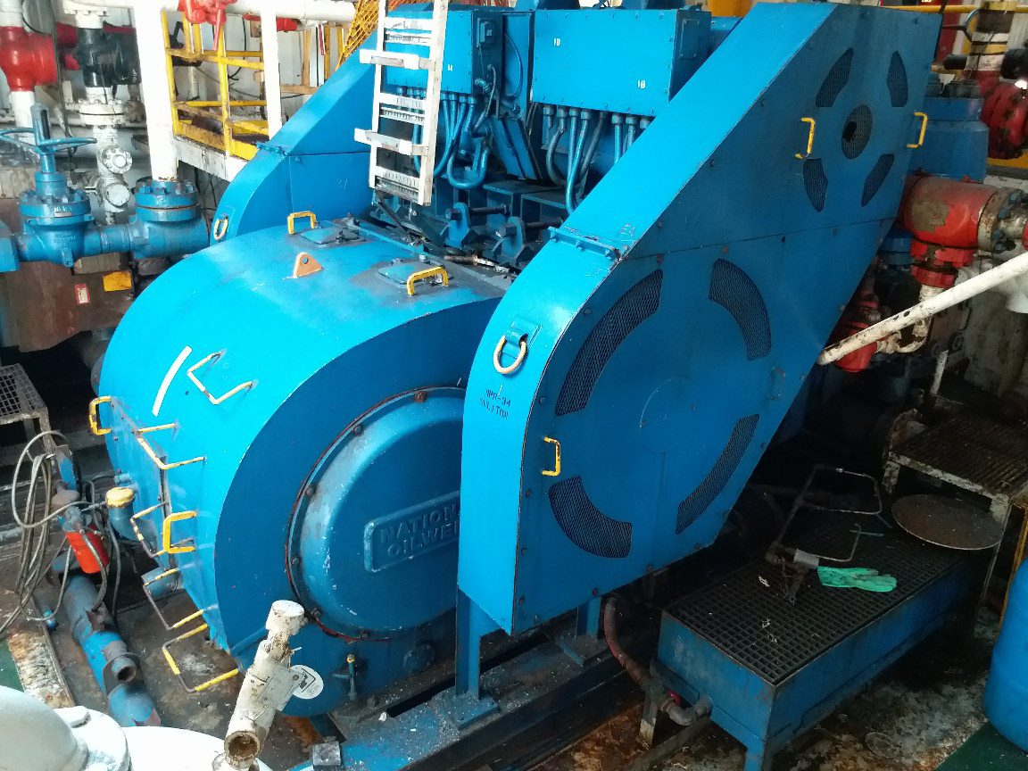
The NOV FC-1600 Triplex Mud Pump is made of rugged Fabriform construction and designed for optimum performance under extreme drilling conditions. It is compact and occupies less space, yet delivers unequaled performance. The pumps are backed by several decades of design and manufacturing experience, and are considered leaders in the field.
NOV FC-1600 Triplex Mud Pump is conservatively rated at relatively low rpm. This reduces the number of load reversals in heavily stressed components and increases the life of the fluid end parts through conservative speeds and valve operation.
The NOV FC-1600 Triplex Mud Pump design provides an inherently balanced assembly. No additional counterbalancing is required for smooth operation. No inertia forces are transmitted to the pumps’ mountings.
A Triplex Mud Pump sometimes referred to as a drilling mud pump or mud drilling pump. NOV FC-1600 Triplex Mud Pump is a reciprocating piston/plunger pump designed to circulate drilling fluid under high pressure (up to 7,500 psi) down the drill string and back up the annulus. A mud pump is an important part of the equipment used for oil well drilling.

Explore a wide variety of small drilling mud pump for sale on Alibaba.com and enjoy exquisite deals. The machines help maintain drilling mud circulation throughout the project. There are many models and brands available, each with outstanding value. These small drilling mud pump for sale are efficient, durable, and completely waterproof. They are designed to lift water and mud with efficiency without using much energy or taking a lot of space.
The primary advantage of these small drilling mud pump for sale is that they can raise water from greater depths. With the fast-changing technology, purchase machines that come with the best technology for optimum results. They should be well adapted to the overall configuration of the installation to perform various operations. Hence, quality products are needed for more efficiency and enjoyment of the machines" full life expectancy.
Alibaba.com offers a wide selection of products with innovative features. The products are designed for a wide range of flow rates that differ by brand. They provide cost-effective options catering to different consumer needs. When choosing the right small drilling mud pump for sale for the drilling project, consider factors such as size, shape, and machine cost. More powerful tools are needed when dealing with large projects such as agriculture or irrigation.
Alibaba.com provides a wide range of small drilling mud pump for sale to suit different tastes and budgets. The site has a large assortment of products from major suppliers on the market. The products are made of durable materials to avoid corrosion and premature wear during operations. The range of products and brands on the site assures quality and good value for money.

This patent application incorporates by reference the patent application having attorney docket number 0301757-NP2, titled: DRYWALL MUD PUMP WITH CLAMP OR IMPROVED FOOT VALVE, having the same inventor and filed on the same date. These two patent applications have certain disclosure in common but were filed with different claims.
The joints between drywall sheets are typically filled and sealed with strips of paper or fiberglass mat and drywall joint compound, also called “joint compound”, “drywall mud”, or just “mud”. Joint compound may be made, for example, of water, limestone, expanded perlite, ethylene-vinyl acetate polymer and attapulgite. Joint compound may be applied as a viscous fluid that is thick enough to maintain its shape while it dries and hardens. In addition to forming joints, drywall mud is used to cover nail or screw heads, form a smooth or flat surface, and provide a texture over the surface. Paint or wall paper is typically applied over the drywall sheets and drywall joint compound.
Workers often specialize in the installation of drywall, and in large projects, different crews install the drywall panels (drywall hangers) from those who finish the joints and apply the joint compound (tapers or mud men). Workers who specialize in drywall installation often use specialized tools to increase their productivity. A number of tools have been invented and used for dispensing drywall joint compound. U.S. Pat. No. 7,473,085 (by Werner Schlecht), for example, describes a drywall finishing tool that is commonly referred to as a “flat box”, which is used to apply drywall joint compound between sheets of drywall, for instance. Further, drywall joint compound has been mixed at the job site in buckets, and various pumps have been used to pump the mud from the buckets into drywall tools such as flat boxes.
U.S. patent application Ser. No. 11/292,238, publication 2007/0122301 (also by Werner Schlecht) describes a drywall mud pump, for example. Various prior art drywall mud pumps used a piston in a main cylinder. In many cases, however, the piston did not travel the full length of the main cylinder. As a result, main cylinder sizes were made fairly large so that sufficient volume of drywall mud was pumped with each stroke of the pump. Further, in a number of designs, friction was excessive, making the pumps difficult to use, especially for large projects where workers have had to pump and apply a large quantity of drywall joint compound.
For these and other reasons, needs or potential for benefit exist for drywall mud pumps that are smaller in size, such as in diameter, that have less internal friction, that allow drywall mud to move freely therethrough, that have a longer piston stroke, or a combination thereof, as examples. In addition, in many prior art drywall pump designs, it was necessary to expend effort holding the pump in place while pumping drywall joint compound, which made using the pump more difficult. As a result, needs and potential for benefit exist for drywall mud pumps that do not need to be held in place while being used, as other examples. As further examples, drywall mud pumps are needed, or would be beneficial, that are inexpensive to manufacture, reliable, easy to use, that have a long life, that are easy to service and clean, and that are simple in operation so that typical operators can effectively maintain them, or that have a combination of such features. Room for improvement exists over the prior art in these and other areas that may be apparent to a person of ordinary skill in the art having studied this document. Other needs and potential for benefit may also be apparent to a person of skill in the art of specialized drywall tools.
Various embodiments provide, for example, as an object or benefit, that they partially or fully address or satisfy one or more of the needs, potential areas for benefit, or opportunities for improvement described herein, or known in the art, as examples. Some embodiments of the invention provide, among other things, various apparatuses, drywall mud pumps, and methods of selecting, obtaining, providing, manufacturing, or making such devices, as examples. Drywall mud pumps, for example, may be used to pump drywall joint compound from buckets into tools for dispensing the drywall joint compound, for instance, which may then be used to apply the drywall joint compound between and/or over sheets of drywall. Workers or operators may use such drywall mud pumps, for example, who specialize in the installation of drywall, or specifically, those who finish the joints and apply the joint compound (tapers or mud men), for instance. Various embodiments provide, for example, as an object or benefit, that they provide specialized drywall mud pumps, for instance, to increase the productivity of such workers.
A number of embodiments provide, for example, as objects or benefits, adaptations and improvements to drywall mud pumps in which a piston may travel a greater length of the main cylinder. As a result, in certain embodiments, main cylinder sizes may be smaller while still providing sufficient volume of drywall mud with each stroke of the pump. Further, in some embodiments, friction may be reduced, making the pumps less difficult to use, especially for large projects where workers may have to pump and apply a large quantity of drywall joint compound. Further, in some embodiments, drywall mud may move more freely through the pump, in comparison with certain prior art alternatives for instance. In addition, in some embodiments, it may require less effort to hold the pump in place while pumping drywall joint compound, which may make using the pump less difficult. In particular embodiments, drywall mud pumps may not need to be held in place by the operator while being used, for examples. Moreover, particular embodiments provide, as an object or benefit, for instance, drywall mud pumps that are inexpensive to manufacture, reliable, easy to use, that have a long life, that are easy to service and clean, and that are simple in operation so that typical operators can effectively maintain them.
Benefits of various embodiments of the invention exist over the prior art in these and other areas that may be apparent to a person of ordinary skill in the art having studied this document. These and other aspects of various embodiments of the present invention may be realized in whole or in part in various drywall mud pumps as shown, described, or both in the figures and related description herein. Other objects and benefits may also be apparent to a person of skill in the art of specialized drywall tools, for example.
In specific embodiments, this invention provides various drywall mud pumps for pumping drywall joint compound from a bucket into a drywall tool, for instance. In a number of these embodiments, such a drywall mud pump may include, for example, a main cylinder having a top end and an bottom end, a rod having a longitudinal axis, a first end, and a second end, and a piston which, when the drywall mud pump is assembled, is located within the main cylinder and is attached to the rod. In various embodiments, when the drywall mud pump is assembled, the second end of the rod is located within the main cylinder. Such embodiments may also include a pump head having an output aperture, and when the drywall mud pump is assembled, the pump head may be connected to the top end of the main cylinder and the rod may pass through the pump head, for example.
Various embodiments may further include a structural component, and when the drywall mud pump is assembled, the structural component may be rigidly attached to the main cylinder or to the pump head, for instance, and may extend from the main cylinder or the pump head to a pivot point, for example. Further, a number of such embodiments may include a handle which may include, for example, a first member and a second member. Further still, in various embodiments, when the drywall mud pump is assembled, the first member may be pivotably connected to the first end of the rod, the second member may be pivotably connected to the structural component at the pivot point, and the first member may slidably or telescopically engage the second member, for instance, to allow the rod to travel in a substantially straight line along the longitudinal axis while the second member rotates about the pivot point.
In particular such embodiments, when the drywall mud pump is assembled, the structural component is rigidly attached to the pump head and extends from the pump head to the pivot point. The structural component may be a separate piece from the pump head, for example. Further, some embodiments may include, for example, a bearing mounted within the second member, and when the drywall mud pump is assembled, part of the first member may fit inside the bearing and may extend into the second member.
Even further, some such embodiments may include a clamp, for example, configured to secure the drywall mud pump to a side of a bucket. In various embodiments, the clamp may include a force-amplification mechanism, for example, and a contact surface to contact the exterior of the bucket. In addition, in a number of embodiments, when the drywall mud pump is assembled and is installed within a bucket, the contact surface may face towards the main cylinder to secure the main cylinder within the bucket by compressing the side of the bucket between the contact surface and the main cylinder, for instance.
Furthermore, particular embodiments may include, for example, a foot valve, which, when the drywall mud pump is assembled, may be attached to the bottom end of the main cylinder allowing drywall joint compound to flow into the main cylinder through the foot valve, but substantially preventing drywall joint compound from flowing out of the main cylinder through the bottom end of the main cylinder. In certain embodiments, the foot valve may include, for example, a pin and two semi-circular-shaped rigid flaps that hingedly rotate about the pin.
In other embodiments, the invention also provides various drywall mud pumps that include, for example, such a main cylinder, such a rod, and such a piston. In these embodiments, the piston may include, for example, at least one orifice through the piston to pass drywall joint compound when the piston is traveling downward in the main cylinder. In various embodiments, the piston may further include at least one flapper to block the at least one orifice to substantially prevent passage of drywall joint compound through the piston when the piston is traveling upward in the main cylinder. Such embodiments may further include a pump head, such as described above, and the pump head may include, for example, a seal around the rod.
These embodiments may further include a structural component, and when the drywall mud pump is assembled, the structural component may be attached in rigid relation to the main cylinder or to the pump head and may extend to a pivot point in rigid relation to the main cylinder. Even further, these embodiments may include a handle that may include, for example, a first member, a second member, and a bearing which may include, for instance, multiple balls or PTFE. In various embodiments, when the drywall mud pump is assembled, the first member may be pivotably connected to the first end of the rod, the second member may be pivotably connected to the structural component at the pivot point, and the first member may slidably engage the second member through the bearing, for example.
Such embodiments may have other features previously mentioned for other embodiments as well. For example, in some embodiments, the first member slidably engages the second member, part of the first member may fit inside the second member, the drywall mud pump may include a foot valve (e.g., as described above), or a combination thereof. Furthermore, in some embodiments, the drywall mud pump may include, for example, a clamp configured to secure the drywall mud pump to a side of a bucket, which may be a toggle clamp, for instance.
The invention also provides various methods, for example, of selecting, obtaining, or providing a drywall mud pump for pumping drywall joint compound from a bucket into a drywall tool. Such methods may include, for example, various acts, which may be performed in any order or in the order listed, as examples. In some such methods, these acts may include, for instance, selecting, obtaining, or providing a body that may include, for example, an inlet to take in drywall joint compound from the bucket, and an output aperture to deliver drywall joint compound to the drywall tool. Various such methods may further include acts of selecting, obtaining, or providing a driver to move the drywall joint compound through the body, and selecting, obtaining, or providing a structural component which, when the drywall mud pump is assembled, may be attached to the body and may extend to a pivot point. Such methods may also include, for further example, an act of selecting, obtaining, or providing a handle that may include, for example, a first member and a second member. In various embodiments, when the drywall mud pump is assembled, the first member may be connected in driving relation to the driver, the second member may be pivotably connected to the structural component at the pivot point, and the first member may slidably or telescopically (or both) engage the second member while the second member rotates about the pivot point, for instance.
In some embodiments, such methods may further include, for example, an act of selecting, obtaining, or providing a bearing, such as a PTFE bearing, for example, which, when the drywall mud pump is assembled, is mounted within the second member. Further, in various embodiments, when the drywall mud pump is assembled, part of the first member fits inside the bearing and extends into the second member. Moreover, particular embodiments may include, for example, an act of selecting, obtaining, or providing a clamp (e.g., as described above) configured to secure the drywall mud pump to a side of a bucket. Furthermore, some embodiments may further include, for example, an act of selecting, obtaining, or providing an inlet valve, which, when the drywall mud pump is assembled, is attached to the inlet of the body, allowing drywall joint compound to flow into the body through the inlet valve, but substantially preventing drywall joint compound from flowing out of the body through the inlet. In certain embodiments, the inlet valve may include, for example, a pin and two semi-circular-shaped rigid flaps that hingedly rotate about the pin.
In various embodiments the act of selecting, obtaining, or providing the driver may further include selecting, obtaining, or providing a piston having at least one orifice therethrough to pass drywall joint compound through the piston, and having at least one flapper to block the at least one orifice to prevent passage of drywall joint compound through the piston. Further, in some embodiments, the act of selecting, obtaining, or providing the body may include selecting, obtaining, or providing a main cylinder, and in particular embodiments, such methods may further include, for example, an act of selecting, obtaining, or providing a rod which, when the drywall mud pump is assembled, extends from the first member to the driver. Still further, in some embodiments, when the drywall mud pump is assembled, the structural component may be attached in rigid relation to the body and the pivot point may be in rigid relation to the body.
FIG. 7 is a cross sectional front view of another embodiment of a drywall mud pump, this embodiment having a toggle clamp and shown clamped inside a bucket;
FIG. 11 is a partial cross sectional view of a the handle of the drywall mud pump shown in FIGS. 7 and 8 with the grip and the pivot clamp omitted, showing, among other things, the other parts of the second member including the bearing;
FIG. 16 is an isometric view of the flappers and tube of an inlet valve or foot valve which may be part of the drywall mud pump shown in FIGS. 7 and 8, or other embodiments described herein, for example;
FIG. 27 is a flow chart illustrating, among other things, an example of a method of selecting, obtaining, or providing a drywall mud pump, for example, for pumping drywall joint compound from a bucket into a drywall tool.
Among other things, various embodiments are, include, obtain, or provide various drywall mud pumps, for example, for pumping drywall joint compound from a bucket into a drywall tool. FIGS. 1-4 illustrate a first embodiment 10 of a drywall mud pump, FIGS. 5 and 6 illustrate a second embodiment 50 of a drywall mud pump, and FIGS. 7 and 8 illustrate a third embodiment 70 of a drywall mud pump, as examples. These figures illustrate assembled drywall mud pumps. Such pumps may be sold, shipped, or stored partially or fully disassembled, however. In a number of embodiments, a drywall mud pump may include, for example, a body, which may be or include a main cylinder (e.g., 11, 51, or 71) having (e.g., in the position shown of normal operation) a top end (e.g., 111, 511, or 711) and an bottom end (e.g., 112, 512, or 712), a rod (e.g., 12, 52, or 72) having a longitudinal axis, a first end (e.g., 121, 521, or 721), and a second end (e.g., 122 or 722), and a piston (e.g., 33 or 73 shown in FIGS. 3, 4, and 7). In a number of embodiments, when the drywall mud pump (e.g., 10, 50, or 70) is assembled, the piston (e.g., 33 or 73) may be located within the main cylinder (e.g., 11, 51, or 71) and may be attached to the rod (e.g., 12, 52, or 72). Pistons 33 and 73 are examples of drivers to move drywall joint compound through the body of drywall mud pumps 10 and 70.
In various embodiments, when the drywall mud pump (e.g., 10, 50, or 70) is assembled, the second end (e.g., 122 or 722) of the rod (e.g., 12, 52, or 72) is located within the main cylinder (e.g., 11, 51, or 71), for instance, attached to the piston (e.g., 33 or 73). Such embodiments may also include a pump head (e.g., 14, 54, or 74), for instance, which may be part of the body, having an output aperture (e.g., 144, 544, 744), and when the drywall mud pump (e.g., 10, 50, or 70) is assembled, the pump head (e.g., 14, 54, or 74) may be connected to the top end (e.g., 111, 511, or 711) of the main cylinder (e.g., 11, 51, or 71), for example, with fasteners, screws, bolts, clips, pins, or the like, as examples (e.g., clips 117 are shown for this purpose in FIGS. 1-6). In a number of embodiments, the rod (e.g., 12, 52, or 72) may pass through the pump head (e.g., 14, 54, or 74), for example. In a number of embodiments, the pump head (e.g., 14, 54, or 74) may include a seal around the rod (e.g., 12, 52, or 72), for example, an elastomeric o-ring or a u-cup, which may substantially prevent drywall joint compound from leaking out of the pump around the rod when the pump is used.
Various embodiments may further include a handle (e.g., 17, 57, or 77 shown in FIGS. 1 to 8) and a bracket or structural component (e.g., 15, 55, or 75) to support the handle of the pump. In a number of embodiments, when the drywall mud pump (e.g., 10, 50, or 70) is assembled, the structural component (e.g., 15, 55, or 75) may be rigidly attached to the main cylinder (e.g., 11, 51, or 71) or to the pump head (e.g., 14, 54, or 74), for instance, and may extend from the main cylinder (e.g., 11, 51, or 71) or the pump head (e.g., 14, 54, or 74) to a pivot point (e.g., 16, 56, or 76), for example. FIG. 9 further illustrates structural component 75 (introduced in FIG. 7) having pivot point 76 at one end and pins or fasteners 99 at the other end to attach structural component 75 to pump head 74, for example.
In various embodiments, the structural component (e.g., 15, 55, or 75) may be attached in rigid relation to the main cylinder (e.g., 11, 51, or 71) or to the pump head (e.g., 14, 54, or 74) (or both) and may extend to a pivot point (e.g., 16, 56, or 76) in rigid relation to the main cylinder (e.g., 11, 51, or 71), for example. In different embodiments, this may be accomplished by attaching the structural component (e.g., 15, 55, or 75) directly to the main cylinder (e.g., 11, 51, or 71) or to the pump head (e.g., 14, 54, or 74), or may be accomplished by attaching the structural component (e.g., 15, 55, or 75) to one or more other components that may be attached to the main cylinder (e.g., 11, 51, or 71) or to the pump head (e.g., 14, 54, or 74), or both, as examples.
As used herein, in this context, two parts being in “rigid relation” means that the parts do not move (e.g., translate or rotate) significantly relative to each other (other than due to insignificant elastic deformation of the material) while the drywall mud pump is in operation. Further, as used herein, two parts being rigidly attached to each other means that the parts are in “rigid relation”. Being “rigidly attached” or in “rigid relation” does not exclude the possibility that the two parts are detachable, for example, for disassembly, cleaning, shipping, or storage of the drywall mud pump, as examples. In fact, in many embodiments, the structural component (e.g., 15, 55, or 75) may be detachable from the pump head (e.g., 14, 54, or 74), cylinder (e.g., 11. 51, or 71), or both, for example.
In a number of embodiments, the handle (e.g., 17, 57, or 77 shown in FIGS. 1 to 8) may include, for example, a first member (e.g., 171, 571, or 771) and a second member (e.g., 172, 572, or 772). Further still, in various embodiments, when the drywall mud pump (e.g., 10, 50, or 70) is assembled, the first member (e.g., 171, 571, or 771) may be pivotably connected to the first end (e.g., 121, 521, or 721) of the rod (e.g., 12, 52, or 72), the second member (e.g., 172, 572, or 772) may be pivotably connected to the structural component (e.g., 15, 55, or 75), for instance, at the pivot point (e.g., 16, 56, or 76), or both, as examples.
Various such embodiments include a handle (e.g., 17, 57, or 77) which, when the drywall mud pump (e.g., 10, 50, or 70) is assembled, may be pivotably connected to the first end (e.g., 121, 521, or 721) of the rod (e.g., 12, 52, or 72), and may be pivotably connected to the structural component (e.g., 15, 55, or 75) at the pivot point (e.g., 16, 56, or 76). Some such handles may include the first member (e.g., 171, 571, or 771) and the second member (e.g., 172, 572, or 772) previously mentioned. FIG. 10 further illustrates first member 771 (e.g., of handle 77) introduced in FIG. 7. In the embodiments illustrated in FIGS. 1-4 and 7-8, for example, the first member (e.g., 171 or 771 of handle 17 or 77) is connected in driving relation (e.g., via rod 12 or 72) to the piston (e.g., 33 or 73), which are examples of drivers.
In the embodiment illustrated, when the drywall mud pump (e.g., 10 or 70) is assembled, part of the first member (e.g., 171 or 771) may fit inside the bearing (e.g., 37 or 737) and may extend into the second member (e.g., 172, 572, or 772). In a number of embodiments, the bearing (e.g., 37 or 737) may be a linear ball bearing, for example, and may include a sleeve-like outer ring and several rows of balls retained by cages. The cages or ball tracks may be oriented to provide for low friction rolling motion in a linear direction (e.g., in the axial direction). The cages or ball tracks may then curve around to return the balls to be used again. The return cages or ball tracks, and the portions of the cages and ball tracks that curve, may be deeper to prevent the balls from contacting the moving surface (e.g., first member 171, 571, or 771) when the balls are traveling in a different direction.
In various embodiments, when the drywall mud pump (e.g., 10, 50, or 70) is assembled, the first member (e.g., 171, 571, or 771) may be pivotably connected to the first end (e.g., 121, 521, or 721) of the rod (e.g., 12, 52, or 72), the second member (e.g., 172, 572, or 772) may be pivotably connected to the structural component (e.g., 15, 55, or 75) at the pivot point (e.g., 16, 56, or 76), and the first member (e.g., 171, 571, or 771) may slidably engage the second member (e.g., 172, 572, or 772) through the bearing (e.g., 37 or 737), for example. Such pivotable connections may include a pin or a fastener, such as a screw or a bolt, as examples.
As shown in FIG. 7, handle 77 also includes grip 773 which may be made of an elastomeric material and may be attached to elongated member 113, second member 772, or handle 77, for example, with an adhesive. As further illustrated in FIG. 7, and shown in detail in FIG. 12, handle 77 and second member 772 thereof also includes pivot clamp 775 which extends from elongated member 113, to pivot point 76. Pivot point 76 may include a pin or fastener (e.g., a screw or bolt) that handle 77 may rotate about when pump 70 is in use. A separate fastener may pass through hole 125 in pivot clamp 775 to tighten pivot clamp 775 around elongated member 113 to secure pivot clamp 775 in place on handle 77.
In the illustrated embodiments, when the drywall mud pump (e.g., 10, 50, or 70) is assembled, the structural component (e.g., 15, 55, or 75) is rigidly attached to the pump head (e.g., 14, 54, or 74) and extends from the pump head (e.g., 14, 54, or 74) to the pivot point (e.g., 16, 56, or 76). The structural component (e.g., 15, 55, or 75) may be a separate piece from the pump head (e.g., 14, 54, or 74), for example, as shown, and may be attached thereto with fasteners, such as screws or bolts, for instance (e.g., pins or fasters 99 shown in FIG. 9). In other embodiments, a structural component (e.g., in lieu of 15, 55, or 75) may pivotably attach to the pump head, as another example. In the embodiments illustrated, structural members 15, 55, and 75 are formed from flat plate, for example. Other embodiments may have a different shape, such as having an I-beam cross section, being tubular (e.g., round, square, rectangular, or oval), or being an angle beam or a channel, as examples. Structural member 55 shown in FIGS. 5 and 6 illustrates that one or more cut outs or holes may be formed in structural members, for instance, to reduce the amount of material, reduce weight, provide attachment points, or the like, as examples. In some embodiments, a structural member (e.g., corresponding to 15, 55, or 75) may be a truss or may consist of two, three, four, or more sub-members, as other examples.
FIGS. 1, 3, and 7 illustrate that a number of embodiments may also include a clamp (e.g., 18 or 78), which may be configured to secure (e.g., by clamping) the drywall mud pump (e.g., 10 or 70) to a side of the bucket (e.g., 80 shown in FIGS. 7 and 8). Bucket 80 may be a common five-gallon plastic bucket, for example. In various embodiments, the clamp (e.g., 18 or 78) may include a force-amplification mechanism (e.g., 181 or 781), for example, and a contact surface (e.g., 182 or 782), for instance, to contact the exterior of the bucket (e.g., 80). In the embodiments shown, when the drywall mud pump (e.g., 10 or 70) is assembled and is installed within a bucket (e.g., 80), the contact surface (e.g., 182 or 782) may face towards the main cylinder (e.g., 11 or 71) to secure the main cylinder (e.g., 11 or 71) within the bucket (e.g., 80), for example, by compressing the side of the bucket (e.g., 80) between the contact surface (e.g., 182 or 782) and the main cylinder (e.g., 11 or 71), for instance.
FIGS. 1 and 3 illustrate that in some embodiments, the drywall mud pump (e.g., 10) further includes a clamp bracket (e.g., 19) which, when the drywall mud pump (e.g., 10) is assembled, may extend from the pump head (e.g., 14) to the clamp (e.g., 18). In embodiment 10 of the drywall mud pump, clamp bracket 19 rigidly attaches to pump head 14, and clamp 18 attaches to clamp bracket 19. In other embodiments, the clamp (e.g., 78 shown in FIG. 7) may attach directly to the pump head (e.g., 74), or the clamp (e.g., 78) may attach directly to a ring that may attach to the pump head (e.g., 74) or to the main cylinder (e.g., 71), as examples. In some embodiments, a clamp may attach directly or indirectly to the main cylinder (e.g., 11, 51, or 71). In various embodiments, the clamp may be attached such that at least part of the clamp is in rigid relation to the main cylinder, the pump head, or both, for example.
In the embodiment shown in FIGS. 1-4, clamp 18 includes an arc-shaped jaw 185 having concave surface 182 to contact the exterior of the bucket. In this embodiment, when drywall mud pump 10 is assembled, concave surface 182 faces away from force-amplification mechanism 181 and concave surface 182 faces towards main cylinder 11 for clamping main cylinder 11 within the bucket. In this embodiment, claim 18 is a screw-type clamp, and force-amplification mechanism 181 is a threaded screw mechanism that is operated by rotating handle 183. Other embodiments of force-amplification mechanisms (e.g., 781) may use leavers, cams, or the like, as other examples.
As illustrated in FIGS. 5 and 6, in some embodiments, the drywall mud pump (e.g., 50) may include a foot plate (e.g., 59) which, when the drywall mud pump (e.g., 50) is assembled, may be attached to the pump head (e.g., 54) and may extend, for example, parallel to the main cylinder (e.g., 51), for instance, at least as far (e.g., downward) from the pump head (e.g., 54) as the bottom end (e.g., 512) of the main cylinder (e.g., 51) or from the bottom of the drywall mud pump (e.g., 50). In this embodiment, rather than clamping to a bucket, the operator steps on lower portion 592 of foot plate 59 while pumping to stabilize drywall mud pump 50. Certain embodiments may have a clamp and a foot plate, as another example.
Furthermore, particular embodiments may include, for example, an inlet valve or a foot valve (e.g., 42 or 742 shown in FIGS. 1 to 4 and 7 to 8), which, when the drywall mud pump (e.g., 10, 50, or 70) is assembled, may be attached to the bottom end (e.g., 112, 512, 712) of the main cylinder (e.g., 11, 51, or 71). The bottom end (e.g., 112, 512, 712) of the main cylinder (e.g., 11, 51, or 71) or the foot valve (e.g., 42 or 742), as examples, may be, or form, an inlet to take in drywall joint compound, for example, from bucket 80. A foot valve (e.g., 42 or 742) may allow drywall joint compound to flow into the main cylinder (e.g., 11, 51, or 71), for instance, from the bucket (e.g., 80) through the foot valve (e.g., 42 or 742), but may substantially prevent drywall joint compound from flowing out of the main cylinder (e.g., 11, 51, or 71) through the bottom end (e.g., 112, 512, 712) of the main cylinder (e.g., 11, 51, or 71).
Foot valve 42 and foot valve 742 are examples of inlet valves, which, when the drywall mud pump (e.g., 10, 50, or 70) is assembled, are (one such valve is) attached to the inlet of the body (e.g., main cylinder 11, 51, or 71) allowing drywall joint compound to flow into the inlet and into the body through the inlet valve, but substantially preventing drywall joint compound from flowing out of the body through the inlet. As used herein, a foot valve (e.g., 42 or 742) “substantially” prevents drywall joint compound from flowing out of the body or main cylinder (e.g., 11, 51, or 71), for instance, through the inlet or bottom end (e.g., 112, 512, 712) if, when the drywall mud pump is in use, the amount of drywall joint compound that passes up through the inlet valve or foot valve during an upward stroke of the piston, for example, is at least twice the amount of drywall joint compound that passes downward through the foot valve during a downward stroke of the piston. Considerably better performance may be accomplished, however, in many embodiments.
In certain embodiments, the foot valve (e.g., 42 or 742) may include, for example, a pin (e.g., 32 shown in FIGS. 1-8). In some embodiments, such a pin may have a ring at a first end, a spring detent at a second end, or both (e.g., on opposite ends), as examples. In some embodiments, two semi-circular-shaped rigid flaps may hingedly rotate about the pin (e.g., 32). FIGS. 16-19 illustrate an example of such an embodiment. In this embodiment, semi-circular-shaped rigid flaps 161 and 162 hingedly rotate about tube 163, for example, as the foot valve (e.g., 42 or 742) opens and closes. In other embodiments, corresponding flaps may have a different shape, such as rectangular. In the particular embodiment shown, the pin (e.g., 32) fits inside tube 163 and secures flaps 161 and 162 and tube 163 within the bottom end (e.g., 112, 512, or 712) of the main cylinder (e.g., 11, 51, or 71). In a number of embodiments, the pin (e.g., 32), tube (e.g., 163), or both, may extend through a portion of each of the flaps. In the specific embodiment illustrated, for example, at least when the drywall mud pump (e.g., 10, 50, or 70) is assembled, tube 163 extends through portions 164, 165, 166, 167, and 168 of flaps 161 and 162. Other embodiments may omit tube 163 or may omit the pin (e.g., 32) (or the tube may be the pin) and the tube may perform some or all of the function that the pin performs in the embodiment shown.
As shown in FIGS. 1 and 2, in the embodiment illustrated, pin 32 also attaches base 421 of foot valve 42 (e.g., to cylinder 11). FIG. 20 further illustrates base 421. Base 421 includes feet 422 which may provide space between bottom end 112 of main cylinder 11 and the bottom of the bucket (e.g., 80), for example, so that drywall joint compound can flow relatively freely into foot valve 42. Further feet 422 may partially or fully support drywall mud pump 10 against the bottom of the bucket. As shown in FIG. 20, base 421 includes holes 205 that pin 32 passes through to secure base 421 and foot valve 42 to bottom end 112 of main cylinder 11. Holes 205 may be large enough in diameter to pass pin 32, but too small to pass tube 163, for example.
In the embodiment illustrated, screw 423 shown in FIGS. 1-3 may act as a stop for flaps 161 and 162 preventing the flaps from raising or opening too far. This assures, in this particular embodiment, that flaps 161 and 162 close (i.e., lower) quickly and reliably when piston 33 starts its downward stroke. In many embodiments, foot valve 42 may further include a screen, for example, below flaps 161 and 162, that may serve to prevent debris and solid chunks of drywall joint compound from being drawn into drywall mud pump 10. Such a screen may be retained by or attached to base 421 of foot valve 42, in some embodiments, for example. Foot valve 742 shown in FIG. 7 may be similar to foot valve 42. In some embodiments, drywall mud pump 50 shown in FIGS. 5 and 6 may have a similar foot valve.
FIG. 8 illustrates that various embodiments may include a high filler (e.g., 88), a goose neck (e.g., 89), or both. Although both high filler 88 and goose neck 89 are shown in FIG. 8, only one of high filler 88 or goose neck 89 would be installed on drywall mud pump 70 at a time, in this embodiment. FIGS. 25 and 26 further illustrate high filler 88 and goose neck 89. In the embodiment illustrated, high filler 88 and goose neck 89 are each formed from a piece of tubing having a round cross section and configured at the ends of the tubing to releasably attach to pump head 74 and to a drywall tool. Where high filler 88 and goose neck 89 attach to a drywall dispensing tool, for example, high filler 88 and goose neck 89 may include a bushing, a seal such as an o-ring, or both, as examples. In the embodiment shown, high filler 88 may be used to fill a flat box, for example, without requiring the operator to bend over as far. Further, in this embodiment, goose neck 89 may be used to fill a corner tool that has a cylinder that holds drywall joint compound under pressure from a piston and spring (e.g., a pneumatic spring) for example. In some embodiments, a high filler may discharge over the bucket (e.g., 88) to avoid spills (e.g., so that spills from the high filler fall back into the bucket).
In the embodiment illustrated, high filler 88 and goose neck 89 attach (e.g., one at a time) to output aperture 744 of pump head 74. Output aperture 744, or the end of high filler 88 or goose neck 89 that attaches to the drywall dispensing tool, are examples of outlet apertures to deliver drywall joint compound to the drywall tool. Outlet apertures 144 and 544 are other such examples. In the embodiment illustrated, high filler 88 and goose neck 89 each have two bends. Specifically, high filler 88 has two 90 degree bends, and goose neck 89 has one 90 degree bend and one 180 degree bends. Other embodiments may differ.
FIGS. 5 and 6 illustrate handle 57 in a fully raised and fully lowered position for embodiment 50 of the drywall mud pump. In various embodiments, for example, the handle may rotate between 80 and 120 degrees, or between 90 and 110 degrees, from the fully raised to the fully lowered position, as examples. In specific embodiments, for example, the handle may rotate about 100 degrees from the fully raised to the fully lowered position. As used herein, “about”, when referring to angles of handle rotation, means within plus or minus 5 degrees. In other embodiments, for further example, the handle may rotate about 50, 60, 70, 80, 85, 90, 95, 105, 110, 115, 120, 125, 130, 140, or 150 degrees from the fully raised to the fully lowered position, as other examples.
A number of embodiments include various methods, for example, of selecting, obtaining, or providing a drywall mud pump (e.g., 10, 50, or 70) for pumping drywall joint compound from a bucket (e.g., 80) into a drywall tool (e.g., a flat box). Such methods may include, for example, various acts, which may be performed in various sequences or orders, examples of which include the order listed herein or shown on the drawings.
In some methods (e.g., method 270 shown in FIG. 27), an act may include, for instance, selecting, obtaining, or providing a body (e.g., act 271 shown in FIG. 27). Examples of such a body (e.g., of act 271) include main cylinder 11, 51, and 71 illustrated in FIGS. 1-8. In some embodiments, such a body (e.g., of act 271) may further include a pump head (e.g., 14, 54, or 74), for instance. In particular embodiments, such a body (e.g., of act 271) may further include other components, such as high filler 88, goose neck 89 or both (e.g., shown in FIGS. 8, 25, and 26), as examples. In a number of embodiments, such a body (e.g., of act 271) may include, for example, an inlet (e.g., bottom end 112, 512, or 712 of main cylinder 11, 51, or 71 or foot valve 42 or 72) to take in drywall joint compound from the bucket (e.g., 80), an output aperture (e.g., 144, 544, or 744 or an opening of a high filler (e.g., 88), a goose neck (e.g., 89), or both) to deliver drywall joint compound to the drywall tool, or both an inlet and an outlet.
Various such methods, including method 270 shown, may further include an act of selecting, obtaining, or providing a driver (e.g., act 272), for instance, to move the drywall joint compound through the body. Examples of such a driver (e.g., of act 272) include pistons 33 and 73 shown, for instance, in FIGS. 3, 7, and 21-24. Another act shown in method 270 is act 273 of selecting, obtaining, or providing a structural component (e.g., 15, 55, or 75 shown in FIGS. 1, 3, 5-7, and 9) which, when the drywall mud pump (e.g., 10, 50, or 70) is assembled, may be attached to the body (e.g., to main cylinder 11, 53, or 73) and may extend to a pivot point (e.g., 16, 56, or 76 shown in FIGS. 1, 3, and 5-7).
In the embodiment illustrated, method 270 also includes, for further example, act 274 of selecting, obtaining, or providing a handle (e.g., 17, 57, or 77 shown in FIGS. 1-8 and 11). Such a handle (e.g., of act 274) may specifically include, for example, a first member (e.g., 171, 571, or 771) and a second member (e.g., 172, 572, or 772). Further, in various embodiments, when the drywall mud pump (e.g., 10, 50, or 70) is assembled, the first member (e.g., 171, 571, or 771) may be connected in driving relation to the driver (e.g., piston 33 or 73, for example, via rod 12 or 72), the second member (e.g., 172, 572, or 772) may be pivotably connected to the structural component (e.g., 15, 55, or 75) at the pivot point (e.g., 16, 56, or 76), and the first member (e.g., 171, 571, or 771) may slidably or telescopically (or both) engage the second member (e.g., 172, 572, or 772) while the second member (e.g., 172, 572, or 772) rotates about the pivot point (e.g., 16, 56, or 76), for instance. In a number of embodiments, the handle (e.g., provided in act 274, for example, handle 17, 57, or 77) may be connected in driving relation to the driver (e.g., piston 33 or 73), may be pivotably connected to the structural component (e.g., 15, 55, or 75) at the pivot point (e.g., 16, 56, or 76), may rotate about the pivot point (e.g., 16, 56, or 76), or a combination thereof, for instance.
In the embodiment shown, methods 270 also includes act 275 of selecting, obtaining, or providing a clamp (e.g., 18 or 78), for example, configured to secure the drywall mud pump (e.g., 10, 50, or 70) to a side of a bucket (e.g., 80). In some embodiments, act 275 (e.g., of method 270) may further include, for example, selecting, obtaining, or providing a force-amplification mechanism (e.g., 181 or 781 shown in FIGS. 1, 7, 13, and 14) and a contact surface (e.g., 182 or 782), for example, to contact the exterior of the bucket (e.g., 80). In various embodiments, when the drywall mud pump (e.g., 10, 50, or 70) is assembled, for instance, the contact surface (e.g., 182 or 782) may face towards the body (e.g., main cylinder 11, 51, or 71), for instance, to secure the body (e.g., main cylinder 11, 51, or 71) within the bucket (e.g., 80), for example, by compressing the side of the bucket (e.g., 80), for instance, between the contact surface (e.g., 182 or 782) and the body (e.g., main cylinder 11, 51, or 71).
Further, in a number of embodiments, the act of selecting, obtaining, or providing the handle (e.g., act 274, for instance, handle 17, 57, or 77) may include selecting, obtaining, or providing a first member (e.g., 171, 571, or 771) and a second member (e.g., 172, 572, or 772). In a number of embodiments, when the drywall mud pump (e.g., 10, 50, or 70) is assembled, the first member (e.g., 171, 571, or 771) may be pivotably connected to the first end (e.g., 121, 521, or 721) of the rod (e.g., 12, 52, or 72), the second member (e.g., 172, 572, or 772) may be pivotably connected to the structural component (e.g., of act 273, for example, structural component 15, 55, or 75) at the pivot point (e.g., 16, 56, or 76).
Additionally, method 270 shown in FIG. 27 further includes, for example, act 276 of selecting, obtaining, or providing an inlet valve (e.g., foot valve 42 or 742), which, when the drywall mud pump (e.g., 10, 50, or 70) is assembled, may be attached to the inlet (e.g., bottom end 112, 512, or 712) of the body (e.g., main cylinder 11, 51, or 71) allowing drywall joint compound to flow into the inlet and into the body through the inlet valve, but substantially preventing drywall joint compound from flowing out of the body through the inlet. In particular embodiments, the inlet valve (e.g., foot valve 42 or 742) may include, for example, a pin (e.g., 32) and two semi-circular-shaped rigid flaps (e.g., 161 and 162 shown in FIGS. 16-19) that hingedly rotate about the pin.
Furthermore, in various embodiments the act of selecting, obtaining, or providing the handle (e.g., act 274, for instance, handle 17, 57, or 77) may further include selecting, obtaining, or providing a bearing (e.g., 37 or 737 shown in FIGS. 3, 7, and 11), as another example. Such a bearing may be or include PTFE, for example. Further, in various embodiments, when the drywall mud pump (e.g., 10, 50, or 70) is assembled, part of the first member (e.g., 171, 571, or 771) may fit inside the bearing (e.g., 37 or 737), may extend into the second member (e.g., 172, 572, or 772), or both, as examples. Moreover, in various embodiments the act of selecting, obtaining, or providing the driver (e.g., act 272) may specifically include selecting, obtaining, or providing a piston (e.g., 33 or 73 shown in FIGS. 3, 4, 7, and 21-24), for instance, having at least one orifice (e.g., 221, 222, 223, or a combination thereof, shown in FIGS. 22 and 23) therethrough to pass drywall joint compound through the piston (e.g., 33 or 73), having at least one flapper (e.g., 240 shown in FIGS. 21 and 24) to block the at least one orifice (e.g., 221, 222, 223, or a combination thereof) to prevent passage of drywall joint compound through the piston (e.g., 33 or 73).
Further, in some embodiments, the act of selecting, obtaining, or providing the body (e.g., act 271) may specifically include selecting, obtaining, or providing a main cylinder (e.g., 11, 51, or 71). Still further, in the embodiment shown, method 270 includes, for example, act 277 of selecting, obtaining, or providing a rod (e.g., 12, 52, or 72). In a number of embodiments, when the drywall mud pump (e.g., 10, 50, or 70) is assembled, the rod (e.g., provided in act 277) may extend from the first member (e.g., 171, 571, or 771) to the driver (e.g., piston 33 or 73), for example. Still further, in some embodiments, when the drywall mud pump (e.g., 10, 50, or 70) is assembled, the structural component (e.g., 15, 55, or 75) may be attached in rigid relation to the body (e.g., to main cylinder 11, 51, or 71), the pivot point (e.g., 16, 56, or 76) may be in rigid relation to the body, or both, as examples.

The Liberty Process LL8 Progressive Cavity Pump is ideal for abrasive pumping applications such as drilling fluids with sand and grit common in fracking operations. As a Mud Pump, the LL8 Series is a popular model on many mobile pumping rigs in use today. Replacement mud pump parts are available as well from our stock and work on other popular manufacturers models.
The Liberty LL8 is a standard flanged pump design manufactured with cast iron or 316 stainless steel pump casings designed in 1, 2, and 3 stages for 75, 150 and 225 psi discharge pressures and a flow rate of 18 up to 100 GPM.
The LL8 is a modular design with simple hardened pinned joint drive assembly. LL8 Rotors are typically hardened tool steel or 316 stainless steel with a hard chrome plating for long life in abrasive pumping applications.
All other wetted parts are either carbon steel or 316 stainless steel. Stators are available in many elastomer materials such as Buna Nitrile, Natural Rubber, EPDM and Viton. The standard seal design is a set of gland packing with a lantern ring set and flush connections. Mechanical seal options for this progressive cavity pump are readily available.
The LL8 represents one of the most popular progressive cavity pumps available for the transport of drilling mud with easily replaceable in-stock parts.
All Categories2 phase separator (6)Separator (6)3 yard dump truck (3)Dump (2)Dump truck (1)Agitator (1)Mixing (1)Air Compressor (3)Compressor (2)Oil Free Compressor (1)Backhoe (14)710 (1)Back hoe (2)Digger (3)Excavator (2)Extenda hoe (2)Loader (1)Rear Actor (1)Tractor (2)Boom (14)Aerial work platform (1)Basket crane (2)Boom Lift (1)Cherry picker (2)Elevating platform (1)Lift (2)Man lift (1)Manlift (1)Mobile elevating work platforms (2)Reachlift (1)Boom Lift (4)Boom (1)Cherry picker (1)Man lift (1)Reach lift (1)Bucket Truck (2)Lift Truck (1)Man lift (1)Cart (3)Mule (1)Side by side (1)UTV (1)Centrifugal Pump (7)Centrifugal Pump (4)Centrifuge (260)Centrifuge (22)Decanter (88)Dewatering (24)Disc Stack (1)Drilling Equipment (36)Processing Equipment (35)Solids Removal (25)Trailer (1)Water Treatment (26)Centrifuge Stand (2)Centrifuge (2)Compactors (3)Double Drum Roller (3)Construction (1)Backhoe Loaders (1)Control Panel (3)Centrifuge (3)Conventional Trucks (2)Day Cab Trucks (2)Conveyor (1)Screw Conveyor (1)Crane (9)Crane (1)Crane Truck (1)Crawler crane (1)Telescopic Crane (2)Truck Mounted Cranes (4)Cryogenic Tank (1)LNG Tank (1)Cuttings Dryer (10)Centrifuge (1)Control Panel (2)Drilling Equipment (1)Dryer (4)Solids control (1)Solids Removal (1)Degasser (2)Atmospheric Degasser (1)Vacuum Degasser (1)Desander (2)Drilling Equipment (1)Solids Removal (1)Desilter (2)Drilling Equipment (1)Solids Removal (1)Diesel Engine (4)Caterpillar (1)Diesel (1)Diesel Engine (1)Engine (1)Drilling (1)Swivels (1)Drilling Equipment (36)Blowout Preventer (1)Centrifuge (5)Cuttings Dryer (1)Degasser (1)Drilling (1)Dryer (1)Mud Cleaning (1)Mud Pump (1)Mud Recycling (1)Power Swivel (2)Processing Equipment (4)Shale Shaker (9)Solids control (6)Solids Removal (1)Tanks (1)Drilling Rigs (6)Drilling Equipment (1)Workover Rig (5)DUMP TRUCK (3)10yard (1)DUMP (1)HAULER (1)Electrical & Electronic Components (1)Wire (1)Engine (1)Natural Gas (1)Excavator (4)145 Excavator (1)30,000 LBS Excavator (1)Digger (1)Heavy machinery (1)Filtration (3)Filtration (1)Forklift (8)Case (1)Fork Lift (1)Lift (1)Rough Terrain (1)Rough Terrain Forklift (1)Toyota (1)Warehouse Forklift (2)Fuel & Lube Trucks (1)GENERATOR (3)POWER (1)TEMP POWER (2)Heater (2)Electric (2)Hydraulic Screen Vibrator (1)Shale Shaker (1)Inline Heater (1)Heater (1)Kill Truck (1)Vacuum Truck (1)Light Tower (7)Disel Engine (3)Generator (1)Light (1)Light Plant (1)Tower (1)Liner hangers (1)Mini Excavator (2)Excavator (1)Mini Ex (1)Mixing Tank (13)Centrifugal Pumps (1)Diesel Driven (1)Diesel Engine (1)Drilling Equipment (1)Mix Tank (1)Mixing (1)Mud Recycling (1)Mud Tank (1)Shaker Tank (1)Tank (4)Mud Guns (1)Mixing (1)Mud Hopper (1)Shearing (1)Mud Pumps (14)Drilling Equipment (2)Gardener Denver (2)Mud Pump (4)Processing Equipment (2)Triplex (2)Triplex pump (2)Oil, Gas and Mining (50)Coiled Tubing (14)Cuttings Dryer (1)Drilling Rigs (5)Fishing Tools (1)Frac blender (1)Frac Pumps (24)Hydraulic Rig (1)Separation Equipment (1)Transmission (1)Triplex Pump (1)Oilfield Equipment (7)Power Swivel (7)Parts (1)Dryer (1)Pressure Washer (7)Processing Equipment (93)Air Stripper (1)Artificial Lift System (1)Centrifuge (48)Cuttings Dryer (2)Dewatering (1)Dryer (1)Filter Press (1)Hopper (1)Mix Tank (2)Oil Water Separation (3)Pump Jack (1)Remediation (1)Rod Pump (1)Separator (2)Shale Shaker (14)Solids Control (2)Tanks and vessels (1)Vessels (2)Water Filtration (1)Water Softener (1)Water Treatment (4)Wemco (2)Production Equipment (2)Combustor (1)Flare (1)Progressing Cavity Pumps (1)Positive Displacement Pumps (1)Pump (14)Centrifugal Pump (3)Centrifuge Feed Pump (1)Diesel Driven (1)Lobe Pump (1)Mulitstage Pump (1)Positive Displacement Pumps (4)Rotary Lobe Pump (1)Self Priming (1)Trash Pump (1)Reach Forklift (3)Forklift (1)Reachlift (1)Up and over (1)Reach Lift (9)FORKLIFT VARIABLE REACH (3)Lift (3)Telehandler (3)SCISSOR LIFT (20)Boom Lift (2)Cherry picker (3)Lift (4)MAN LIFT (2)Manlift (3)REACHLIFT (1)Rough Terrain (1)Scissor (4)Shaker Screen Cleaner (1)Shaker Screens (1)Shaker Screens (1)Screens (1)Shale Shaker (9)Centrifuge (1)Screens (1)Shaker (4)Shaker Screens (1)Shale Shaker (1)Solids Removal (1)Skid steer (6)Bobcat (2)Skidsteer (2)Track (1)Track Skid steer (1)Stand Centrifuge (7)Centrifuge Stand (7)Submersible Pump (1)Pump (1)Tanks & Kettles (1)Coalescer (1)Three phase separator (7)Separator (7)Top Drive (6)Drilling Equipment (2)Drilling Rig (1)Hydraulic (1)TOP DRIVE (1)Well Service Equipment (1)Trash Pump (5)Centrifugal Pump (1)Diesel Driven (1)Diesel Engine (1)Trash Pump (1)Water pump (1)Truck (6)Crew Cab (1)Kill Truck (1)Pickup (1)Reefer Trucks (1)Service & Utility Trucks (2)Vacuum trailer (2)Vac trailer (1)Vacuum (1)Vessels (8)Acid Tank (1)Frac Gel (1)Frac Tank (1)Mix Tank (1)Mud Tank (1)Tank (1)Truck (1)Water tank (1)Warehouse Forklift (2)6k Forklift (1)Forklift (1)Water Treatment (2)Reverse Osmosis (2)WATER TRUCK (3)Tank (1)TANK TRUCK (1)WATER (1)Welder (2)300Amp welder (1)Big Blue (1)WHEEL LOADER (1)3 YARD WHEEL LOADER (1)Winch Trucks (1)

With the necessary tophead rotation speed, head feed speed, and plenty of mud pump options to get the job done, complete your water well drilling, geothermal drilling, and cathodic protection drilling jobs with a single, compact water well drill.
Outfit as down the hole drill or mud drill with the power of 28.5-foot stroke, 40,000 lb pullback, and 8,000 ft-lb torque to handle deeper wells along with weight of steel casing.

(2) Pumps - Triplex W/ Forged Steel Fluid End & Quick Change Caps, 5M Pulsation Dampner, Oteco 3" Shear Relief Valve, Pressure Gauge, Mission 6 X 5 Charge Pump P/B Cat C-18 Diesel Engine, Allison CLT6061 Transmission, Fitted W/ 7" Liners, & Pistons, Master Skidded, (1) Pump No Power or Transmission. Good Condition.
All New Parts In Both Gear & Fluid End, Pump Will Have New Style Gear End, Primered & Painted Buyers Choice, Hyd. Gearbox Available. Rebuilt Condition.


 8613371530291