
mud pump double acting piston pricelist
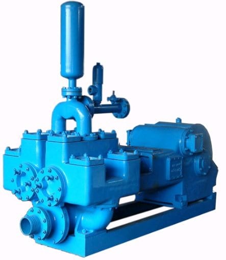
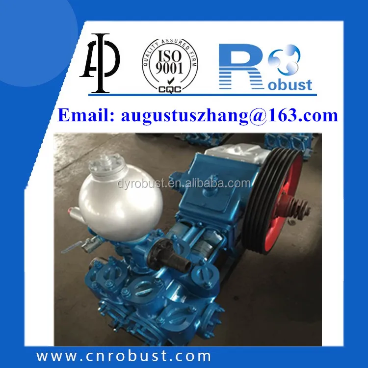
A mud pump is a reciprocating piston/plunger pump designed to circulate drilling fluid under high pressure (up to 7,500 psi (52,000 kPa)) down the drill string and back up the annulus. A duplex mud pump is an important part of the equipment used for oil well drilling.
Duplex mud pumps (two piston/plungers) have generally been replaced by the triplex pump, but are still common in developing countries. Two later developments are the hex pump with six vertical pistons/plungers, and various quintuplex’s with five horizontal piston/plungers. The advantages that Duplex mud pumps have over convention triplex pumps is a lower mud noise which assists with better Measurement while drilling and Logging while drilling decoding.
Use duplex mud pumps to make sure that the circulation of the mud being drilled or the supply of liquid reaches the bottom of the well from the mud cleaning system. Despite being older technology than the triplex mud pump, the duplex mud pumps can use either electricity or diesel, and maintenance is easy due to their binocular floating seals and safety valves.
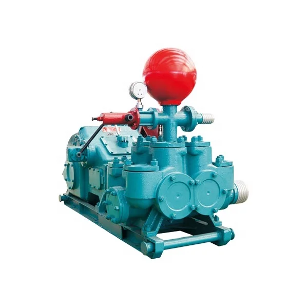
A mud pump is composed of many parts including mud pump liner, mud pump piston, modules, hydraulic seat pullers, and other parts. Parts of a mud pump:housing itself
Duplex pumps are used to provide a secondary means of fuel transfer in the event of a failure of the primary pump. Each pump in a duplex set is sized to meet the full flow requirements of the system. Pump controllers can be set for any of the following common operating modes:Lead / Lag (Primary / Secondary): The lead (primary) pump is selected by the user and the lag (secondary pump operates when a failure of the primary pump is detected.
Alternating: Operates per Lead / Lag (Primary / Secondary) except that the operating pump and lead / lag status alternate on consecutive starts. A variation is to alternate the pumps based on the operating time (hour meter) of the lead pump.
The l-series of l. K-duplex mud pumps is the result of over two decades of incessant research and development by a young team of pains taking engineers, workingread more...
the l-series of l. K-duplex mud pumps is the result of over two decades of incessant research and development by a young team of pains taking engineers, working with an "india-can-doit" mood. They are backed by their close association with advanced pump technology and actualread more...
We provide a qualitative range of mud pumps, which are immensely used in construction, agriculture, waste water management and many other industries. These High Pressure Duplex Double Acting Mud Pumps are primarily reciprocating plunger devices designed forread more...
Established in year 1996, Maskill Enterprises is the leading Wholesaler Trader of Submersible Pump, Self Priming Pump and Double Wall Corrugated Pipe.
" GSL" Make Reciprocating Duplex Double Acting Mud Pump idle for water well drilling, core drilling, shallow crude oil drilling. Also sutable for Cement Slurry, Crude Oil, Boiler Feed, Sweage Mud pumps are suitble for mounting on skid, Trailer and on drilling rigs.
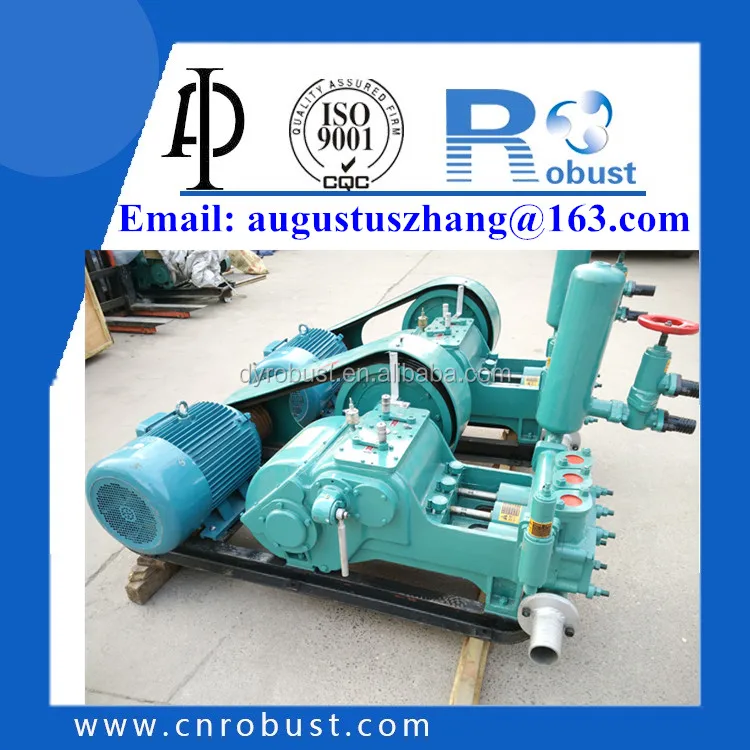
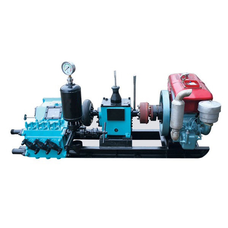
1. Horizontal, triplex, single acting reciprocation piston pumps. The pump can choose diesel motor power, It has simple operation, convenient, can achieve close range or remote control.
3. This pump adopts the car transmission,Can get six different discharge and pressure,Reasonable configuration parameters selection,The construction technology can satisfy different requirements.
4. Mainly used drilling fluid in supply for 2000m about core drilling coal field geology,metallurgy geology,hydrogeololgy,drilling fluid can use mud and water, the coal water etc.
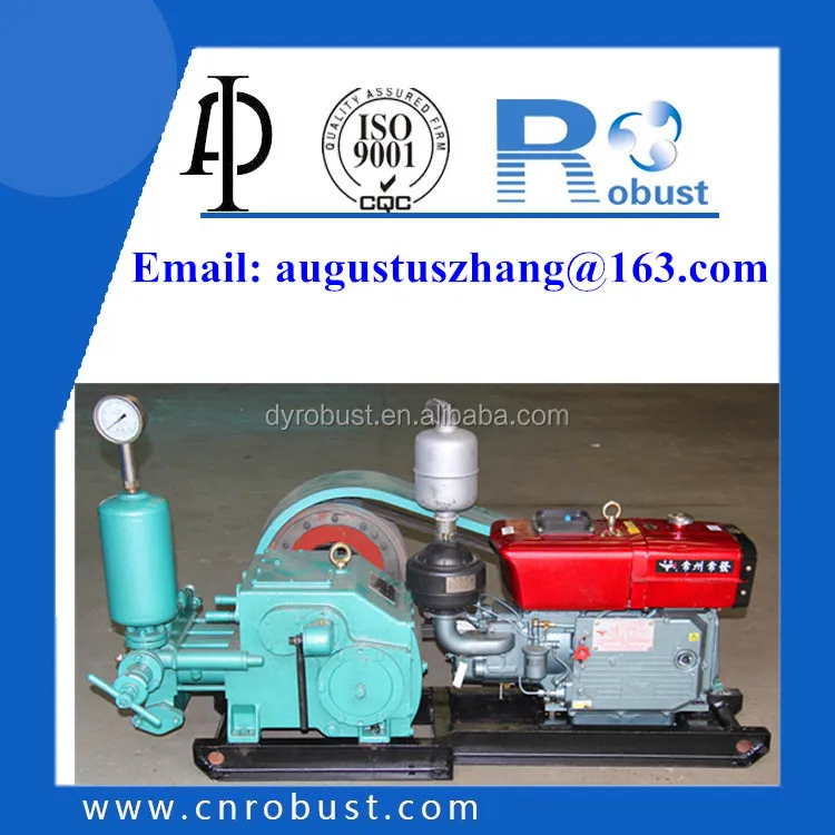
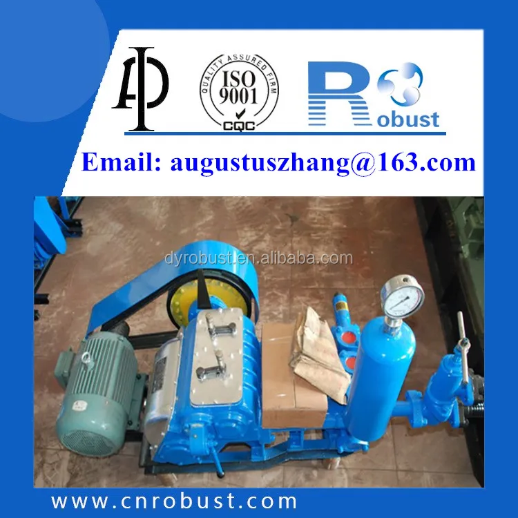
2.BW250 slurry pump have two cylinders with different diameters and four gear shifts.Output and drilling depth are adjustable,so it can be used to grout cement slurry or equipped with 1500m drilling machine.
3.BW160/10 slurry pump is widely used in railway, hydraulic engineering, metallurgical engineering, building construction, geological exploration, engineering exploration (within 1000m of the drilling depth), etc.
Explore a wide variety of piston pump price on Alibaba.com and enjoy exquisite deals. The machines help maintain drilling mud circulation throughout the project. There are many models and brands available, each with outstanding value. These piston pump price are efficient, durable, and completely waterproof. They are designed to lift water and mud with efficiency without using much energy or taking a lot of space.
The primary advantage of these piston pump price is that they can raise water from greater depths. With the fast-changing technology, purchase machines that come with the best technology for optimum results. They should be well adapted to the overall configuration of the installation to perform various operations. Hence, quality products are needed for more efficiency and enjoyment of the machines" full life expectancy.
Alibaba.com offers a wide selection of products with innovative features. The products are designed for a wide range of flow rates that differ by brand. They provide cost-effective options catering to different consumer needs. When choosing the right piston pump price for the drilling project, consider factors such as size, shape, and machine cost. More powerful tools are needed when dealing with large projects such as agriculture or irrigation.
Alibaba.com provides a wide range of piston pump price to suit different tastes and budgets. The site has a large assortment of products from major suppliers on the market. The products are made of durable materials to avoid corrosion and premature wear during operations. The range of products and brands on the site assures quality and good value for money.
Established in 1991, Laxmi Pumps Private Limited has been producing LADA Submersible Pumps exclusively with reliable quality and excellent after-sales service. LADA is the brand under which our products are manufactured and marketed.
Established in 1991, Laxmi Pumps Private Limited has been producing LADA Submersible Pumps exclusively with reliable quality and excellent after-sales service. LADA is the brand under which our products are manufactured and marketed.
We are one of the renowned Manufacturers, Exporters and Suppliers of precision-engineered Mud Pumps in Gujarat (India). Our LX-series of Mud Pumps sold under the brand name “Laxmi” is manufacturing in compliance with international standards as our company isISO 9001: 2008 certified.
Developed by a team of highly qualified engineers using computer-aided designing and manufacturing technologies, our Mud Pumps are double-acting and piston (reciprocating) type. They are designed to endure high pressure and high discharge application. In addition, they have several in-built design and constructional features that ensure high efficiency without much electricity intake.
Our Mud Pumps are available in various models and can be ordered in bulk. In addition, we offer them at very economical prices and provide customized solutions.
Our Mud Pumps are duplex double acting reciprocating type made from a single piece alloy casting capable of handling high discharge and high pressure applications. These are ideally suitable for seismograph survey, water well, oil well, core drilling mud and cement service applications. Moreover, the pumps feature continuous tooth herring-bone gears fitted with eccentric for easy economical replacement.
We have the requisite technical and commercial expertise to expand our business to new horizons of growth. Company’s main strength is its Quality and Innovative designs. This is the reason why our products are well established as POWERSAVER PUMPS in the market.
Who better to repair your pump than the company you bought it from in the frist place. Gardner Denver offers you two locations dedicated to rebuilding,
pump in a shop designed to get your unit back to work as quickly as possible. Supported with a full-line of original Gardner Denver parts, our Ft. Worth,

Each pump is passing a full load factory acceptance test to verify its mechanical and hydraulic performance. WARMAN* Centrifugal Slurry Pumps GEHO* PD Slurry Pumps LINATEX* Rubber Products VULCO* Wear Resistant Linings CAVEX* Hydrocyclones FLOWAY* PUMPS Vertical Turbine Pumps ISOGATE* Slurry Valves MULTIFLO* Mine Dewatering Solutions HAZLETON* Specialty Slurry Pumps LEWIS PUMPS™ Vertical Chemical Pumps WEIR MINERALS SERVICES Weir Minerals Netherlands b.v. designs, manufactures and markets piston, piston diaphragm and hose pumps under the brand name GEHO®. Since 1957 our company has...
Consultancy You are welcome to let our experts review your slurry pumping needs (application). Customers in the global mining, mineral processing and power industries usually call on GEHO® pumps for advice in the development of a slurry processing system and in studying the technical and economic feasibility of a project. We have considerable knowledge and experience in all aspects of slurry, ranging from sample testing, slurry characterisation, flow behaviour, pressure loss calculation and flow sheet optimisation to the selection and bidding of the appropriate pump. This consultancy work...
Product innovation The piston pump, model ZPR, was developed in the 1960"s in conjunction with municipalities to meet an emerging demand for the transport of sewage sludge. A large number of these early pumps are still in operation in Europe and elsewhere and transfer screened raw sludge, feed filter presses or pump drilling mud. Even today, municipal customers often prefer this double-acting crankshaft driven piston pump to ram pumps and hose-type piston diaphragm pumps. We have supplied more than 10,000 wellpoint dewatering pumps over 50 years. These two-cylinder vacuum piston pumps lower...
TZP – Triplex single-acting crankshaft driven piston pump The TZP is a three-cylinder single-acting crankshaft driven piston pump. The principal difference to a ZPR is the single-acting piston. The TZP does not use a stuffing box. It reduces the number of wear parts and makes this design attractive to the handling of more abrasive slurry and higher pressure. The capital expenditure of this piston pump is substantially lower than that of an equivalent size diaphragm pump and offsets the piston and liner (wear) parts usage when pumping mildly abrasive slurry and/or moderate pressure. The...
ZPM and TZPM – Duplex and triplex crankshaft driven piston diaphragm pump Model TZPM The principal difference between a piston and a piston diaphragm pump is the genuine diaphragm that protects the piston and liner from the sliding contact with the abrasive slurry. The diaphragm is a pre-moulded design that eliminates elongation of the elastomer. Its long fatigue life allows for routine annual maintenance to be carried out. The diaphragm position is controlled in either direction of the stroke by adding or removing propelling fluid that fills the cavity between the piston and diaphragm. A...
DHC and DHT – Hydraulic driven piston pump DHC - Piston pump with actuator assisted valves The model DHC piston pump is fitted with large diameter, high lift, actuator assisted suction and discharge valves and handles rather viscous pastes and particles typically not larger than 15 mm. It uses the valve design from the diaphragm pump, except that the valve cone bolts directly onto the actuator rod. The actuator load and activation sequence is arranged such that a valve will not open against the pump discharge pressure. As a result the system is inherently protected against backflow, even if...
DHT – Piston pump with transfer tube The model DHT’s pump water end comprises a hopper with transfer tube. This S-form pipe pivots on the discharge side whilst the inlet is intermediate between the opening of the paired cylinders. At the end of a suction stroke it covers the cylinder opening and isolates the filled cylinder from the suction hopper. During the subsequent discharge stroke, the piston forces the product through the tube into the discharge pipe. During switch over the tube partly overlaps and short-circuits the cylinders for a fraction of a second. When pumping a paste...
Pump Systems Surface disposal of tailings, as a thickened paste, as opposed to conventional slurry deposition in a pond, offers considerable advantages and reduces the environmental impact. GEHO® has played an active role in the development, promotion and global acceptance of the high concentration tailings disposal system. The pioneering red mud (alumina tailings) Thickened Tailings Disposal (TTD) systems were the result of alumina producers and key equipment suppliers working in close partnership. They combined efforts in the development of the concept, laboratory testing, process design,...
Aftermarket support By aligning our own objectives with those of our enduser customers, we are forming long-term mutually beneficial partnerships. We provide comprehensive support under flexible agreements tailored to customer needs. The unique design and technology of a GEHO® pump warrants that we supervise its installation and start-up. We also provide on-site technical product training to enhance personnel performance in maintenance and operations. Participants review and exercise proper start-up, shutdown, maintenance and troubleshooting procedures and are taught about the function and...

As the name suggests, the mud pump is a device used to transport mud-like liquids with high consistency or more particles. The pump is an important part of mechanical equipment and a machine that converts mechanical energy into liquid pressure energy. Now it has been widely used in drilling, construction sites, enterprise production, mud pond pumping, etc. And now it is used in daily production. Only being familiar with the working principle of the pump can help the operator to use the pump more skillfully and make it play an effective role in industrial production. The following is a detailed description of the working principle and application of the mud pump.
Commonly used mud pumps are piston or plunger type. The crankshaft of the pump is driven by the power machine to rotate, and the crankshaft drives the piston or plunger to reciprocate in the pump cylinder through the crosshead. Under the alternate action of suction and discharge valves, the purpose of pressure feeding and circulating flushing fluid is realized.
According to the function, the mud pump can also be divided into two types: single-acting and double-acting. The single-acting type only completes one suction and drainage action in one cycle of the reciprocating motion of the piston. The double-acting mud pump completes two suction and drainage actions every time it reciprocates. If classified according to the number of cylinders of the pump, there are three types: single cylinder, double cylinder and triple cylinder.
Its working principle is to rely on the reciprocating motion of the piston to make the working volume of the pump chamber change periodically, and then suck in and discharge liquid. It is composed of pump cylinder, piston, water inlet and outlet valves, water inlet and outlet pipes, connecting rod and transmission device, and is more suitable for drilling operations with high pressure and small flow.
The plunger pump is one of the important devices of the hydraulic system. The pressure of the pump depends on the depth of the borehole, the resistance of the channel through which the flushing fluid passes, and the nature of the flushing fluid delivered. The deeper the hole, the greater the resistance of the pipeline and the higher the pressure required. As the diameter and depth of the borehole change, the displacement of the pump is required to be adjusted at any time.
A gearbox is installed in the pump mechanism or its speed is adjusted by a hydraulic motor to achieve the purpose of changing the displacement. In order to accurately grasp the change of the pressure and displacement of the pump, a flow meter and a pressure gauge should be installed on the mud pump to let the drilling personnel understand the operation of the pump at any time, and at the same time judge whether the condition in the hole is normal through the pressure change to prevent accidents in the hole.
The two main parameters of mud pump performance are displacement and pressure. Displacement is calculated by several liters per minute, which is related to the diameter of the borehole and the return speed of the required flushing fluid and the bottom of the hole, that is to say, the larger the diameter of the hole, the greater the required displacement. The upward return speed of the flushing fluid is required to be able to flush the rock cuttings and rock dust cut off by the drill bit away from the bottom of the hole in time and reliably carry them to the surface. During geological core drilling, the upward and downward speed is generally about 0.4 to 1.0 m/min.
A mud pump is a machine that delivers flushing fluid such as mud or water to the borehole during oil drilling. It is an important part of drilling equipment. In the process of oil drilling, the mud pump injects mud into the downhole with the drilling of the drill bit. During this process, the mud pump can cool the drill bit, clean the drilling tool, and some wastes such as cuttings are brought back to the ground to clean the well.
In the commonly used positive circulation drilling, the surface flushing medium, clear water, mud or polymer flushing fluid, is passed through the high-pressure hose, faucet and the center hole of the drill string to the bottom of the drill bit under a certain pressure to cool the drill bit to achieve the purpose of removing and transporting the cuttings to the surface.
During the drilling process, the drill bit continuously breaks the rock at the bottom of the hole to generate cuttings and circulate the mud flushing fluid, transport the debris to the ground and keep the bottom of the hole clean, which is beneficial for the drill bit to continue to break the rock. In addition to this, mud pumps also provide energy for drilling tools, delivering energy to power augers, hydraulic hammers and other hydraulic percussion drilling tools.
In some special work, such as plugging and sealing holes, the mud pump can be used to pour special substances one by one into the grout or other blocking substances in the holes. Oil drilling generally adopts positive circulation drilling. Under a certain pressure, the mud pump passes through water, high-pressure hose and the center hole of the drill string, and the clean water, mud or polymer is transported to the bottom of the well.
Slurry pumps are used to transport abrasive slurry containing solid particles in mining, metallurgy, coal and other industries. It is a coaxial pump with a water pump and a motor. During operation, the motor shaft drives the impeller of the pump to rotate, and transmits energy to the slurry medium to generate a certain flow, drive the solid flow, and realize slurry transportation.
The mud pump is an important process equipment for drilling operations. Whether the drilling project can be completed safely, on time and efficiently, its regular maintenance and maintenance cannot be underestimated. Correct and timely maintenance of the drilling pump is a necessary measure to ensure the normal operation of the mud pump and prolong its service life. Any pump use should pay attention to this link.
When the oil level is stable, check the oil level at the power supply at least once a day. If using a chain drive, check the oil level in the chain case. Observe the working condition of cylinder liner and piston. It is normal for a small amount of mud to flow from the piston pull rope.
Check the cylinder bore of the frame. If there is a large buildup of mud and oil, it should be cleaned up. Check the water tank of the spray pump. If the water is insufficient, it should be replenished. If the water quality is polluted, it should be replaced and the water tank should be cleaned at the same time.
Check whether the inflation pressure of the air chamber meets the requirements of the operating conditions. The safety valve should be checked frequently and replaced in time. Loosen the piston rod clamp every day, and check whether the connecting surface of the clamp cone, piston rod and intermediate tie rod is clean.
Check the valve cover seal and cylinder liner seal (including the seal between the wear plate and the liquid cylinder) alarm holes frequently. If the mud is discharged, replace the corresponding sealing ring in time.
The mud pump piston is a key part for providing mud circulation, but its sealing performance often fails under complex working conditions, which shorten its service life. Inspired by the ring segment structure of earthworms, the bionic striped structure on surfaces of the mud pump piston (BW-160) was designed and machined, and the sealing performances of the bionic striped piston and the standard piston were tested on a sealing performance testing bench. It was found the bionic striped structure efficiently enhanced the sealing performance of the mud pump piston, while the stripe depth and the angle between the stripes and lateral of the piston both significantly affected the sealing performance. The structure with a stripe depth of 2 mm and angle of 90° showed the best sealing performance, which was 90.79% higher than the standard piston. The sealing mechanism showed the striped structure increased the breadth and area of contact sealing between the piston and the cylinder liner. Meanwhile, the striped structure significantly intercepted the early leaked liquid and led to the refluxing rotation of the leaked liquid at the striped structure, reducing the leakage rate.
Mud pumps are key facilities to compress low-pressure mud into high-pressure mud and are widely used in industrial manufacture, geological exploration, and energy power owing to their generality [1–4]. Mud pumps are the most important power machinery of the hydraulic pond-digging set during reclamation [5] and are major facilities to transport dense mud during river dredging [6]. During oil drilling, mud pumps are the core of the drilling liquid circulation system and the drilling facilities, as they transport the drilling wash fluids (e.g., mud and water) downhole to wash the drills and discharge the drilling liquids [7–9]. The key part of a mud pump that ensures mud circulation is the piston [10, 11]. However, the sealing of the piston will fail very easily under complex and harsh working conditions, and consequently, the abrasive mud easily enters the kinematic pair of the cylinder liner, abrading the piston surfaces and reducing its service life and drilling efficiency. Thus, it is necessary to improve the contact sealing performance of the mud pump piston.
As reported, nonsmooth surface structures can improve the mechanical sealing performance, while structures with radial labyrinth-like or honeycomb-like surfaces can effectively enhance the performance of gap sealing [12–14]. The use of nonsmooth structures into the cylinder liner friction pair of the engine piston can effectively prolong the service life and improve work efficiency of the cylinder liner [15–17]. The application of nonsmooth grooved structures into the plunger can improve the performance of the sealing parts [18, 19]. The nonsmooth structures and sizes considerably affect the sealing performance [20]. Machining a groove-shaped multilevel structure on the magnetic pole would intercept the magnetic fluid step-by-step and slow down the passing velocity, thus generating the sealing effect [21–23]. Sealed structures with two levels or above have also been confirmed to protect the sealing parts from hard damage [24]. The sealing performance of the high-pressure centrifugal pump can be improved by adding groove structures onto the joint mouth circumference [25]. The convex, pitted, and grooved structures of dung beetles, lizards, and shells are responsible for the high wear-resistance, resistance reduction, and sealing performance [26–28]. Earthworms are endowed by wavy nonsmooth surface structures with high resistance reduction and wear-resistance ability [29]. The movement of earthworms in the living environment is very similar to the working mode of the mud pump piston. The groove-shaped bionic piston was designed, and the effects of groove breadth and groove spacing on the endurance and wear-resistance of the piston were investigated [30]. Thus, in this study, based on the nonsmooth surface of earthworms, we designed and processed a nonsmooth striped structure on the surface of the mud pump piston and tested the sealing performance and mechanism. This study offers a novel method for prolonging the service life of the mud pump piston from the perspective of piston sealing performance.
The BW-160 mud pump with long-range flow and pressure, small volume, low weight, and long-service life was used here. The dimensions and parameters of its piston are shown in Figure 1.
A striped structure was designed and processed on the contact surface between the piston cup and the cylinder liner. The striped structure was 5 mm away from the outermost part of the lip, which ensured the lip could contact effectively with the cylinder liner. Based on the structural dimensions of the piston cup, we designed a 2-stripe structure, and the very little stripe space affected the service life of the piston [30]. Thus, the stripe space of our bionic piston was set at 5 mm. According to the machining technology, two parameters of stripe depth h and the angle between the stripes and lateral of the piston α were selected (Figure 2).
A mud pump piston sealing performance test bench was designed and built (Figure 3). This bench mainly consisted of a compaction part and a dynamic detection part. The compaction part was mainly functioned to exert pressure, which was recorded by a pressure gauge, to the piston sealed cavity. This part was designed based on a vertical compaction method: after the tested piston and the sealing liquid were installed, the compaction piston was pushed to the cavity by revolving the handle. Moreover, the dynamic detection part monitored the real-time sealing situation and was designed based on the pressure difference method for quantifying the sealing performance. This part was compacted in advance to the initial pressure P0 (0.1 MPa). After compaction, the driving motor was opened, and the tested piston was pushed to drive the testing mud to reciprocate slowly. After 1 hour of running, the pressure P on the gauge was read, and the pressure difference was calculated as , which was used to measure the sealing performance of the piston.
To more actually simulate the working conditions of the mud pump, we prepared a mud mixture of water, bentonite (in accordance with API Spec 13A: viscometer dial reading at 600 r/min ≥ 30, yield point/plastic viscosity radio ≤ 3, filtrate volume ≤ 15.0 ml, and residue of diameter greater than 75 μm (mass fraction) ≤ 4.0%), and quartz sand (diameter 0.3–0.5 mm) under complete stirring, and its density was 1.306 g/cm³ and contained 2.13% sand.
The test index was the percentage of sealing performance improvement β calculated aswhere and are the pressure differences after the runs with the standard and the bionic pistons, respectively ().
The sealing performance tests showed the striped structures all effectively enhanced the contact sealing between the piston and the cylinder liner. In particular, the increase of sealing performance relative to the standard piston minimized to 21.05% in the bionic striped piston with a stripe depth of 3 mm and angle of 45° and maximized to 90.79% in the bionic striped piston with the stripe depth of 2 mm and angle of 90°. Range analysis showed the sealing performance of pistons was affected by the stripe depth h and angle α, and these two parameters (h and α) have the same effect on the sealing performance.
Figure 4 shows the effects of stripe depth and angle on the sealing performance of mud pump pistons. Clearly, the stripe depth should be never too shallow or deep, while a larger angle would increase the sealing performance more (Figure 4).
Sealing validity tests were conducted to validate the sealing performance of the bionic striped pistons. It was observed whether the sealing liquid would leak at the tail of the cylinder liner, and the time of leakage was recorded. The standard piston and the most effective bionic piston were selected to compare their sealing performances.
Both the standard piston and the bionic striped piston leaked, which occurred after 84 and 249 minutes of operation, respectively (Figure 5). Figure 6 shows the pressures of the two pistons during testing. Clearly, the sealing pressure of the standard piston declined rapidly before the leakage, but that of the bionic piston decreased very slowly. After the leakage, the reading on the pressure gauge in the standard piston declined to 0 MPa within very short time, but that of the bionic piston decreased much more slowly.
The beginning time of leakage was inconsistent between the standard and bionic pistons (84 minutes vs. 249 minutes). In order to compare the leakage of these two pistons, the leaked liquid was collected when the piston started to leak. The volume of the leaked liquid was measured using a graduated cylinder every 5 minutes from the 84th minute and 249th minute, respectively (both considered as 0 minute), for 20 minutes. Figure 7 shows the leaked amounts of the standard piston and the bionic piston. Clearly, after the leakage and failure, the leaking speed and amount of the bionic piston were both smaller than those of the standard piston.
The piston lips and the cylinder liner were under interference contact, and their mutual extrusion was responsible for the lip sealing. Thus, a larger pressure between the piston lips and the cylinder liner reflects a higher lip sealing effect.
The bionic striped piston with the highest sealing performance (h = 2 mm, α = 90°) was selected for the sealing mechanism analysis and named as the bionic piston. The 3D point cloud data of standard piston were acquired by using a three-dimensional laser scanning system (UNIscan, Creaform Inc., Canada). Then, the standard piston model was established by the reverse engineering technique. The striped structure of the bionic piston was modeled on basis of the standard piston.4.1.1. Contact Pressure of Piston Surface
The standard piston and the bionic piston were numerically simulated using the academic version of ANSYS® Workbench V17.0. Hexahedral mesh generation method was used to divide the grid, and the size of grids was set as 2.5 mm. The piston grid division is shown in Figure 8, and the grid nodes and elements are shown in Table 3. The piston cup was made of rubber, which was a hyperelastic material. A two-parameter Mooney–Rivlin model was selected, with C10 = 2.5 MPa, C01 = 0.625 MPa, D1 = 0.3 MPa−1, and density = 1120 kg/m3 [32, 33]. The loads and contact conditions related to the piston of the mud pump were set. The surface pressure of the piston cup was set as 1.5 MPa, and the displacement of the piston along the axial direction was set as 30 mm. The two end faces of the cylinder liner were set as “fixed support,” and the piston and cylinder liner were under the frictional interfacial contact, with the friction coefficient of 0.2.
Figure 9 shows the pressure clouds of the standard piston and the bionic piston. Since the simulation model was completely symmetrical and the pressures at the same position of each piston were almost the same, three nodes were selected at the lip edge of each piston for pressure measurement, and the average of three measurements was used as the lip edge pressure of each piston. The mutual extrusion between piston and cylinder liner happened at the lip, and thereby the larger of the lip pressure was, the better the sealing performance was. The lip pressure of the standard piston was smaller than that of the bionic piston (2.7371 ± 0.016 MPa vs. 3.0846 ± 0.0382 MPa), indicating the striped structure enhanced the mutual extrusion between the bionic piston and the cylinder liner and thereby improved the sealing performance between the lips and the cylinder liner. As a result, sand could not easily enter the piston-cylinder liner frictional interface, which reduced the reciprocated movement of sand and thereby avoided damage to the piston and the cylinder liner.
Figure 10 shows the surface pressures from the lip mouth to the root in the standard piston and the bionic piston. The surface pressure of the bionic piston surpasses that of the standard piston, and the pressure at the edge of each striped structure changes suddenly: the pressures at the striped structure of the bionic piston are far larger than at other parts. These results suggest the contact pressure between the edges of the striped structures and the cylinder liner is larger, and the four edges of the two striped structures are equivalent to a four-grade sealed lip mouth formed between the piston and the cylinder liner, which generates a multilevel sealing effect and thereby largely enhances the sealing effect of the piston.
The piston surface flow field was numerically simulated using the CFX module of the software ANSYS® Workbench V17.0. The side of the lips was set as fluid inlet, and the other side as fluid outlet, as shown in Figure 11. The inlet and outlet were set as opening models, and the external pressure difference between them was 0 Pa. The moving direction of the piston was opposite to the fluid flow direction. The fluid region was divided into grids of 0.2 mm, while the striped structures were refined to grade 2.
Figures 12 and 13 show the surface streamline clouds and sectional streamline clouds of the two pistons at the early stage of leakage when the fluid entered the interface. Clearly, compared with the standard piston, when the surface-leaked liquid from the bionic piston passed the striped structure, the streamlines were sparse and significantly decreased in number, and the flow velocity declined more. The flow velocity decreased from 0.9348 m/s to 0.7555 m/s in the bionic piston and from 0.9346 m/s to 0.9262 m/s in the standard piston. It shows that, after the blockage by the striped structures, the striped structure more significantly intercepted the leaked liquid and could reduce the leakage rate of the piston, thereby enhancing the sealing effect.
Figure 13 shows the section leakage streamline of the standard piston and the bionic piston. Clearly, compared with the standard piston, when the leaked liquid of the bionic piston flowed through the striped structures, the streamlines would reflux and reverse inside the striped structures, indicating the striped structures can efficiently store the leaked liquid and slow down the leakage.
To better validate the sealing mechanism of the bionic striped pistons, a piston’s performance testing platform was independently built and the sealed contact of the pistons was observed. A transparent toughened glass cylinder liner was designed and machined. The inner diameter and the assembly dimensions of the cylinder liner were set according to the standard BW-160 mud pump cylinder liners. The sealing contact surfaces of the pistons were observed and recorded using a video recorder camera.
Figure 14 shows the surface contact of the standard piston and the bionic piston. Clearly, in the contact areas between the standard piston and the cylinder liner, only the narrow zone at the lip mouth contacted, as the contact width was only 4.06 mm. On the contrary, the contact areas between the bionic piston and the cylinder liner were all very wide, as the contact width was about 18.36 mm, and the sealed area was largely enlarged (892.8 mm2 vs. 4037.6 mm2) according to the contact areas calculated, which were favorable for improving the sealing performance.
Figure 15 shows the oil film left after the piston running. The oil film width of the bionic piston was far larger than that of the standard piston (20.48 mm vs. 2.28 mm). The striped structure of the bionic piston could store the lubricating oils, and uniform oil films were formed after its repeated movement, which reduced the friction between the piston and the cylinder liner, so that the seal failure of the piston would not happen due to excessive abrasion.
(1)The bionic striped structure significantly enhanced the sealing performance of the mud pump pistons. The stripe depth and the angle between the stripes and the piston were two important factors affecting the sealing performance of the BW-160 mud pump pistons. The sealing performance was enhanced the most when the stripe depth was 2 mm and the angle was 90°.(2)The bionic striped structure can effectively enhance the contact pressure at the piston lips, enlarge the mutual extrusion between the piston and the cylinder liner, reduce the damage to the piston and cylinder liner caused by the repeated movement of sands, and alleviate the abrasion of abrasive grains between the piston and the cylinder liner, thereby largely improving the sealing performance.(3)The bionic striped structure significantly intercepted the leaked liquid, reduced the leakage rate of pistons, and effectively stored the leaked liquid, thereby reducing leakage and improving the sealing performance.(4)The bionic striped structure led to deformation of the piston, enlarged the width and area of the sealed contact, the stored lubricating oils, and formed uniform oil films after repeated movement, which improved the lubrication conditions and the sealing performance.
The bionic striped structure can improve the sealing performance and prolong the service life of pistons. We would study the pump resistance in order to investigate whether the bionic striped structure could decrease the wear of the piston surface.

Mechanical pumps serve in a wide range of applications such as pumping water from wells, aquarium filtering, pond filtering and aeration, in the car industry for water-cooling and fuel injection, in the energy industry for pumping oil and natural gas or for operating cooling towers and other components of heating, ventilation and air conditioning systems. In the medical industry, pumps are used for biochemical processes in developing and manufacturing medicine, and as artificial replacements for body parts, in particular the artificial heart and penile prosthesis.
When a pump contains two or more pump mechanisms with fluid being directed to flow through them in series, it is called a multi-stage pump. Terms such as two-stage or double-stage may be used to specifically describe the number of stages. A pump that does not fit this description is simply a single-stage pump in contrast.
In biology, many different types of chemical and biomechanical pumps have evolved; biomimicry is sometimes used in developing new types of mechanical pumps.
Pumps can be classified by their method of displacement into positive-displacement pumps, impulse pumps, velocity pumps, gravity pumps, steam pumps and valveless pumps. There are three basic types of pumps: positive-displacement, centrifugal and axial-flow pumps. In centrifugal pumps the direction of flow of the fluid changes by ninety degrees as it flows over an impeller, while in axial flow pumps the direction of flow is unchanged.
Some positive-displacement pumps use an expanding cavity on the suction side and a decreasing cavity on the discharge side. Liquid flows into the pump as the cavity on the suction side expands and the liquid flows out of the discharge as the cavity collapses. The volume is constant through each cycle of operation.
Positive-displacement pumps, unlike centrifugal, can theoretically produce the same flow at a given speed (rpm) no matter what the discharge pressure. Thus, positive-displacement pumps are constant flow machines. However, a slight increase in internal leakage as the pressure increases prevents a truly constant flow rate.
A positive-displacement pump must not operate against a closed valve on the discharge side of the pump, because it has no shutoff head like centrifugal pumps. A positive-displacement pump operating against a closed discharge valve continues to produce flow and the pressure in the discharge line increases until the line bursts, the pump is severely damaged, or both.
A relief or safety valve on the discharge side of the positive-displacement pump is therefore necessary. The relief valve can be internal or external. The pump manufacturer normally has the option to supply internal relief or safety valves. The internal valve is usually used only as a safety precaution. An external relief valve in the discharge line, with a return line back to the suction line or supply tank provides increased safety.
Rotary-type positive displacement: internal or external gear pump, screw pump, lobe pump, shuttle block, flexible vane or sliding vane, circumferential piston, flexible impeller, helical twisted roots (e.g. the Wendelkolben pump) or liquid-ring pumps
Drawbacks: The nature of the pump requires very close clearances between the rotating pump and the outer edge, making it rotate at a slow, steady speed. If rotary pumps are operated at high speeds, the fluids cause erosion, which eventually causes enlarged clearances that liquid can pass through, which reduces efficiency.
Hollow disk pumps (also known as eccentric disc pumps or Hollow rotary disc pumps), similar to scroll compressors, these have a cylindrical rotor encased in a circular housing. As the rotor orbits and rotates to some degree, it traps fluid between the rotor and the casing, drawing the fluid through the pump. It is used for highly viscous fluids like petroleum-derived products, and it can also support high pressures of up to 290 psi.
Vibratory pumps or vibration pumps are similar to linear compressors, having the same operating principle. They work by using a spring-loaded piston with an electromagnet connected to AC current through a diode. The spring-loaded piston is the only moving part, and it is placed in the center of the electromagnet. During the positive cycle of the AC current, the diode allows energy to pass through the electromagnet, generating a magnetic field that moves the piston backwards, compressing the spring, and generating suction. During the negative cycle of the AC current, the diode blocks current flow to the electromagnet, letting the spring uncompress, moving the piston forward, and pumping the fluid and generating pressure, like a reciprocating pump. Due to its low cost, it is widely used in inexpensive espresso machines. However, vibratory pumps cannot be operated for more than one minute, as they generate large amounts of heat. Linear compressors do not have this problem, as they can be cooled by the working fluid (which is often a refrigerant).
Reciprocating pumps move the fluid using one or more oscillating pistons, plungers, or membranes (diaphragms), while valves restrict fluid motion to the desired direction. In order for suction to take place, the pump must first pull the plunger in an outward motion to decrease pressure in the chamber. Once the plunger pushes back, it will increase the chamber pressure and the inward pressure of the plunger will then open the discharge valve and release the fluid into the delivery pipe at constant flow rate and increased pressure.
Pumps in this category range from simplex, with one cylinder, to in some cases quad (four) cylinders, or more. Many reciprocating-type pumps are duplex (two) or triplex (three) cylinder. They can be either single-acting with suction during one direction of piston motion and discharge on the other, or double-acting with suction and discharge in both directions. The pumps can be powered manually, by air or steam, or by a belt driven by an engine. This type of pump was used extensively in the 19th century—in the early days of steam propulsion—as boiler feed water pumps. Now reciprocating pumps typically pump highly viscous fluids like concrete and heavy oils, and serve in special applications that demand low flow rates against high resistance. Reciprocating hand pumps were widely used to pump water from wells. Common bicycle pumps and foot pumps for inflation use reciprocating action.
These positive-displacement pumps have an expanding cavity on the suction side and a decreasing cavity on the discharge side. Liquid flows into the pumps as the cavity on the suction side expands and the liquid flows out of the discharge as the cavity collapses. The volume is constant given each cycle of operation and the pump"s volumetric efficiency can be achieved through routine maintenance and inspection of its valves.
This is the simplest form of rotary positive-displacement pumps. It consists of two meshed gears that rotate in a closely fitted casing. The tooth spaces trap fluid and force it around the outer periphery. The fluid does not travel back on the meshed part, because the teeth mesh closely in the center. Gear pumps see wide use in car engine oil pumps and in various hydraulic power packs.
A screw pump is a more complicated type of rotary pump that uses two or three screws with opposing thread — e.g., one screw turns clockwise and the other counterclockwise. The screws are mounted on parallel shafts that have gears that mesh so the shafts turn together and everything stays in place. The screws turn on the shafts and drive fluid through the pump. As with other forms of rotary pumps, the clearance between moving parts and the pump"s casing is minimal.
Widely used for pumping difficult materials, such as sewage sludge contaminated with large particles, a progressing cavity pump consists of a helical rotor, about ten times as long as its width. This can be visualized as a central core of diameter x with, typically, a curved spiral wound around of thickness half x, though in reality it is manufactured in a single casting. This shaft fits inside a heavy-duty rubber sleeve, of wall thickness also typically x. As the shaft rotates, the rotor gradually forces fluid up the rubber sleeve. Such pumps can develop very high pressure at low volumes.
Named after the Roots brothers who invented it, this lobe pump displaces the fluid trapped between two long helical rotors, each fitted into the other when perpendicular at 90°, rotating inside a triangular shaped sealing line configuration, both at the point of suction and at the point of discharge. This design produces a continuous flow with equal volume and no vortex. It can work at low pulsation rates, and offers gentle performance that some applications require.
A peristaltic pump is a type of positive-displacement pump. It contains fluid within a flexible tube fitted inside a circular pump casing (though linear peristaltic pumps have been made). A number of rollers, shoes, or wipers attached to a rotor compresses the flexible tube. As the rotor turns, the part of the tube under compression closes (or occludes), forcing the fluid through the tube. Additionally, when the tube opens to its natural state after the passing of the cam it draws (restitution) fluid into the pump. This process is called peristalsis and is used in many biological systems such as the gastrointestinal tract.
Efficiency and common problems: With only one cylinder in plunger pumps, the fluid flow varies between maximum flow when the plunger moves through the middle positions, and zero flow when the plunger is at the end positions. A lot of energy is wasted when the fluid is accelerated in the piping system. Vibration and
Triplex plunger pumps use three plungers, which reduces the pulsation of single reciprocating plunger pumps. Adding a pulsation dampener on the pump outlet can further smooth the pump ripple, or ripple graph of a pump transducer. The dynamic relationship of the high-pressure fluid and plunger generally requires high-quality plunger seals. Plunger pumps with a larger number of plungers have the benefit of increased flow, or smoother flow without a pulsation damper. The increase in moving parts and crankshaft load is one drawback.
Car washes often use these triplex-style plunger pumps (perhaps without pulsation dampers). In 1968, William Bruggeman reduced the size of the triplex pump and increased the lifespan so that car washes could use equipment with smaller footprints. Durable high-pressure seals, low-pressure seals and oil seals, hardened crankshafts, hardened connecting rods, thick ceramic plungers and heavier duty ball and roller bearings improve reliability in triplex pumps. Triplex pumps now are in a myriad of markets across the world.
Triplex pumps with shorter lifetimes are commonplace to the home user. A person who uses a home pressure washer for 10 hours a year may be satisfied with a pump that lasts 100 hours between rebuilds. Industrial-grade or continuous duty triplex pumps on the other end of the quality spectrum may run for as much as 2,080 hours a year.
The oil and gas drilling industry uses massive semi trailer-transported triplex pumps called mud pumps to pump drilling mud, which cools the drill bit and carries the cuttings back to the surface.
One modern application of positive-displacement pumps is compressed-air-powered double-diaphragm pumps. Run on compressed air, these pumps are intrinsically safe by design, although all manufacturers offer ATEX certified models to comply with industry regulation. These pumps are relatively inexpensive and can perform a wide variety of duties, from pumping water out of bunds to pumping hydrochloric acid from secure storage (dependent on how the pump is manufactured – elastomers / body construction). These double-diaphragm pumps can handle viscous fluids and abrasive materials with a gentle pumping process ideal for transporting shear-sensitive media.
Devised in China as chain pumps over 1000 years ago, these pumps can be made from very simple materials: A rope, a wheel and a pipe are sufficient to make a simple rope pump. Rope pump efficiency has been studied by grassroots organizations and the techniques for making and running them have been continuously improved.
Impulse pumps use pressure created by gas (usually air). In some impulse pumps the gas trapped in the liquid (usually water), is released and accumulated somewhere in the pump, creating a pressure that can push part of the liquid upwards.
Instead of a gas accumulation and releasing cycle, the pressure can be created by burning of hydrocarbons. Such combustion driven pumps directly transmit the impulse from a combustion event through the actuation membrane to the pump fluid. In order to allow this direct transmission, the pump needs to be almost entirely made of an elastomer (e.g. silicone rubber). Hence, the combustion causes the membrane to expand and thereby pumps the fluid out of the adjacent pumping chamber. The first combustion-driven soft pump was developed by ETH Zurich.
It takes in water at relatively low pressure and high flow-rate and outputs water at a higher hydraulic-head and lower flow-rate. The device uses the water hammer effect to develop pressure that lifts a portion of the input water that powers the pump to a point higher than where the water started.
The hydraulic ram is sometimes used in remote areas, where there is both a source of low-head hydropower, and a need for pumping water to a destination higher in elevation than the source. In this situation, the ram is often useful, since it requires no outside source of power other than the kinetic energy of flowing water.
Rotodynamic pumps (or dynamic pumps) are a type of velocity pump in which kinetic energy is added to the fluid by increasing the flow velocity. This increase in energy is converted to a gain in potential energy (pressure) when the velocity is reduced prior to or as the flow exits the pump into the discharge pipe. This conversion of kinetic energy to pressure is explained by the
A practical difference between dynamic and positive-displacement pumps is how they operate under closed valve conditions. Positive-displacement pumps physically displace fluid, so closing a valve downstream of a positive-displacement pump produces a continual pressure build up that can cause mechanical failure of pipeline or pump. Dynamic pumps differ in that they can be safely operated under closed valve conditions (for short periods of time).
Such a pump is also referred to as a centrifugal pump. The fluid enters along the axis or center, is accelerated by the impeller and exits at right angles to the shaft (radially); an example is the centrifugal fan, which is commonly used to implement a vacuum cleaner. Another type of radial-flow pump is a vortex pump. The liquid in them moves in tangential direction around the working wheel. The conversion from the mechanical energy of motor into the potential energy of flow comes by means of multiple whirls, which are excited by the impeller in the working channel of the pump. Generally, a radial-flow pump operates at higher pressures and lower flow rates than an axial- or a mixed-flow pump.
These are also referred to as All fluid pumps. The fluid is pushed outward or inward to move fluid axially. They operate at much lower pressures and higher flow rates than radial-flow (centrifugal) pumps. Axial-flow pumps cannot be run up to speed without special precaution. If at a low flow rate, the total head rise and high torque associated with this pipe would mean that the starting torque would have to become a function of acceleration for the whole mass of liquid in the pipe system. If there is a large amount of fluid in the system, accelerate the pump slowly.
Mixed-flow pumps function as a compromise between radial and axial-flow pumps. The fluid experiences both radial acceleration and lift and exits the impeller somewhere between 0 and 90 degrees from the axial direction. As a consequence mixed-flow pumps operate at higher pressures than axial-flow pumps while delivering higher discharges than radial-flow pumps. The exit angle of the flow dictates the pressure head-discharge characteristic in relation to radial and mixed-flow.
Regenerative turbine pump rotor and housing, 1⁄3 horsepower (0.25 kW). 85 millimetres (3.3 in) diameter impeller rotates counter-clockwise. Left: inlet, right: outlet. .4 millimetres (0.016 in) thick vanes on 4 millimetres (0.16 in) centers
Also known as drag, friction, peripheral, traction, turbulence, or vortex pumps, regenerative turbine pumps are class of rotodynamic pump that operates at high head pressures, typically 4–20 bars (4.1–20.4 kgf/cm2; 58–290 psi).
The pump has an impeller with a number of vanes or paddles which spins in a cavity. The suction port and pressure ports are located at the perimeter of the cavity and are isolated by a barrier called a stripper, which allows only the tip channel (fluid between the blades) to recirculate, and forces any fluid in the side channel (fluid in the cavity outside of the blades) through the pressure port. In a regenerative turbine pump, as fluid spirals repeatedly from a vane into the side channel and back to the next vane, kinetic energy is imparted to the periphery,
As regenerative turbine pumps cannot become vapor locked, they are commonly applied to volatile, hot, or cryogenic fluid transport. However, as tolerances are typically tight, they are vulnerable to solids or particles causing jamming or rapid wear. Efficiency is typically low, and pressure and power consumption typically decrease with flow. Additionally, pumping direction can be reversed by reversing direction of spin.
Steam pumps have been for a long time mainly of historical interest. They include any type of pump powered by a steam engine and also pistonless pumps such as Thomas Savery"s or the Pulsometer steam pump.
Recently there has been a resurgence of interest in low power solar steam pumps for use in smallholder irrigation in developing countries. Previously small steam engines have not been viable because of escalating inefficiencies as vapour engines decrease in size. However the use of modern engineering materials coupled with alternative engine configurations has meant that these types of system are now a cost-effective opportunity.
Valveless pumping assists in fluid transport in various biomedical and engineering systems. In a valveless pumping system, no valves (or physical occlusions) are present to regulate the flow direction. The fluid pumping efficiency of a valveless system, however, is not necessarily lower than that having valves. In fact, many fluid-dynamical systems in nature and engineering more or less rely upon valveless pumping to transport the working fluids therein. For instance, blood circulation in the cardiovascular system is maintained to some extent even when the heart"s valves fail. Meanwhile, the embryonic vertebrate heart begins pumping blood long before the development of discernible chambers and valves. Similar to blood circulation in one direction, bird respiratory systems pump air in one direction in rigid lungs, but without any physiological valve. In microfluidics, valveless impedance pumps have been fabricated, and are expected to be particularly suitable for handling sensitive biofluids. Ink jet printers operating on the piezoelectric transducer principle also use valveless pumping. The pump chamber is emptied through the printing jet due to reduced flow impedance in that direction and refilled by capillary action.
Examining pump repair records and mean time between failures (MTBF) is of great importance to responsible and conscientious pump users. In view of that fact, the preface to the 2006 Pump User"s Handbook alludes to "pump failure" statistics. For the sake of convenience, these failure statistics often are translated into MTBF (in this case, installed life before failure).
In early 2005, Gordon Buck, John Crane Inc.’s chief engineer for field operations in Baton Rouge, Louisiana, examined the repair records for a number of refinery and chemical plants to obtain meaningful reliability data for centrifugal pumps. A total of 15 operating plants having nearly 15,000 pumps were included in the survey. The smallest of these plants had about 100 pumps; several plants had over 2000. All facilities were located in the United States. In addition, considered as "new", others as "renewed" and still others as "established". Many of these plants—but not all—had an alliance arrangement with John Crane. In some cases, the alliance contract included having a John Crane Inc. technician or engineer on-site to coordinate various aspects of the program.
Not all plants are refineries, however, and different results occur elsewhere. In chemical plants, pumps have historically been "throw-away" items as chemical attack limits life. Things have improved in recent years, but the somewhat restricted space available in "old" DIN and ASME-standardized stuffing boxes places limits on the type of seal that fits. Unless the pump user upgrades the seal chamber, the pump only accommodates more compact and simple versions. Without this upgrading, lifetimes in chemical installations are generally around 50 to 60 percent of the refinery values.
Unscheduled maintenance is often one of the most significant costs of ownership, and failures of mechanical seals and bearings are among the major causes. Keep in mind the potential value of selecting pumps that cost more initially, but last much longer between repairs. The MTBF of a better pump may be one to four years longer than that of its non-upgraded counterpart. Consider that published average values of avoided pump failures range from US$2600 to US$12,000. This does not include lost opportunity costs. One pump fire occurs per 1000 failures. Having fewer pump failures means having fewer destructive pump fires.
As has been noted, a typical pump failure, based on actual year 2002 reports, costs US$5,000 on average. This includes costs for material, parts, labor and overhead. Extending a pump"s MTBF from 12 to 18 months would save US$1,667 per year — which might be greater than the cost to upgrade the centrifugal pump"s reliability.
Pumps are used throughout society for a variety of purposes. Early applications includes the use of the windmill or watermill to pump water. Today, the pump is used for irrigation, water supply, gasoline supply, air conditioning systems, refrigeration (usually called a compressor), chemical movement, sewage movement, flood control, marine services, etc.
Because of the wide variety of applications, pumps have a plethora of shapes and sizes: from very large to very small, from handling gas to handling liquid, from high pressure to low pressure, and from high volume to low volume.
Typically, a liquid pump can"t simply draw air. The feed line of the pump and the internal body surrounding the pumping mechanism must first be filled with the liquid that requires pumping: An operator must introduce liquid into the system to initiate the pumping. This is called priming the pump. Loss of prime is usually due to ingestion of air into the pump. The clearances and displacement ratios in pumps for liquids, whether thin or more viscous, usually cannot displace air due to its compressibility. This is the case with most velocity (rotodynamic) pumps — for example, centrifugal pumps. For such pumps, the position of the pump should always be lower than the suction point, if not the pump should be manually filled with liquid or a secondary pump should be used until all air is removed from the suction line and the pump casing.
Positive–displacement pumps, however, tend to have sufficiently tight sealing between the moving parts and the casing or housing of the pump that they can be described as self-priming. Such pumps can also serve as priming pumps, so-called when they are used to fulfill that need for other pumps in lieu of action taken by a human operator.
One sort of pump once common worldwide was a hand-powered water pump, or "pitcher pump". It was commonly installed over community water wells in the days before piped water supplies.
In parts of the British Isles, it was often called the parish pump. Though such community pumps are no longer common, people still used the expression parish pump to describe a place or forum where matters of local interest are discussed.
Because water fro


 8613371530291