
mud pump drilling circulation video supplier

Cameron mud pumps provide superior performance for your onshore or offshore applications. Built on more than 40 years of experience and the successful WH-Series mud pump design, these improved pumps are constructed with premium components to ensure low total cost of ownership and increased reliability.

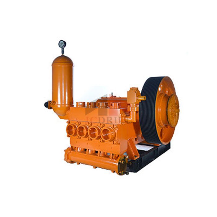
The 2,200-hp mud pump for offshore applications is a single-acting reciprocating triplex mud pump designed for high fluid flow rates, even at low operating speeds, and with a long stroke design. These features reduce the number of load reversals in critical components and increase the life of fluid end parts.
The pump’s critical components are strategically placed to make maintenance and inspection far easier and safer. The two-piece, quick-release piston rod lets you remove the piston without disturbing the liner, minimizing downtime when you’re replacing fluid parts.

The drilling industry has roots dating back to the Han Dynasty in China. Improvements in rig power and equipment design have allowed for many advances in the way crude oil and natural gas are extracted from the ground. Diesel/electric oil drilling rigs can now drill wells more than 4 miles in depth. Drilling fluid, also called drilling mud, is used to help transfer the dirt or drill cuttings from the action of the drilling bit back to the surface for disposal. Drill cuttings can vary in shape and size depending on the formation or design of the drill bit used in the process.
Watch the video below to see how the EDDY Pump outperforms traditional pumps when it comes to high solids and high viscosity materials commonly found on oil rigs.
Solids control equipment including shakers, hydro-cyclones, and centrifuges are utilized to clean the drill cuttings from the drilling fluid, which then allows it to be reused and recirculated. The circuit includes the mixing of the drilling fluid in the rig tanks.
The drilling fluid is prepared to control fluid loss to the formation by the addition of chemicals or mineral agents. Commercial barite or other weighting agents are added to control the hydrostatic pressure exuded on the bottom of the well which controls formation pressures preventing fluid or gas intrusion into the wellbore.
The fluid is charged into high-pressure mud pumps which pump the drilling mud down the drill string and out through the bit nozzles cleaning the hole and lubricating the drill bit so the bit can cut efficiently through the formation. The bit is cooled by the fluid and moves up the space between the pipe and the hole which is called the annulus. The fluid imparts a thin, tough layer on the inside of the hole to protect against fluid loss which can cause differential sticking.
The fluid rises through the blowout preventers and down the flowline to the shale shakers. Shale shakers are equipped with fine screens that separate drill cutting particles as fine as 50-74 microns. Table salt is around 100 microns, so these are fine cuttings that are deposited into the half-round or cuttings catch tank. The drilling fluid is further cleaned with the hydro-cyclones and centrifuges and is pumped back to the mixing area of the mud tanks where the process repeats.
The drill cuttings contain a layer of drilling fluid on the surface of the cuttings. As the size of the drill cuttings gets smaller the surface area expands exponentially which can cause rheological property problems with the fluid. The fluid will dehydrate and may become too thick or viscous to pump so solids control and dilution are important to the entire drilling process.
One of the most expensive and troubling issues with drilling operations is the handling, processing, and circulation of drilling mud along with disposing of the unwanted drill cuttings. The drilling cuttings deposited in the half round tank and are typically removed with an excavator that must move the contents of the waste bin or roll-off box. The excavators are usually rented for this duty and the equipment charges can range from $200-300/day. Add in the cost for the day and night manpower and the real cost for a single excavator can be as much as $1800/day.
Offshore drilling rigs follow a similar process in which the mud is loaded into empty drums and held on the oil platform. When a certain number of filled drums is met, the drums are then loaded onto barges or vessels which take the drilling mud to the shore to unload and dispose of.
Oil field drilling operations produce a tremendous volume of drill cuttings that need both removal and management. In most cases, the site managers also need to separate the cuttings from the drilling fluids so they can reuse the fluids. Storing the cuttings provides a free source of stable fill material for finished wells, while other companies choose to send them off to specialty landfills. Regardless of the final destination or use for the cuttings, drilling and dredging operations must have the right high solids slurry pumps to move them for transport, storage, or on-site processing. Exploring the differences in the various drilling fluids, cutting complications, and processing options will reveal why the EDDY Pump is the best fit for the job.
The Eddy Pump is designed to move slurry with solid content as high as 70-80 % depending on the material. This is an ideal application for pumping drill cuttings. Drill cuttings from the primary shakers are typically 50% solids and 50% liquids. The Eddy Pump moves these fluids efficiently and because of the large volute chamber and the design of the geometric rotor, there is very little wear on the pump, ensuring long life and greatly reduced maintenance cost for the lifetime of the pump.
plumbed to sweep the bottom of the collection tank and the pump is recessed into a sump allowing for a relatively clean tank when the solids are removed. The Eddy Pump is sized to load a roll-off box in 10-12 minutes. The benefit is cuttings handling is quicker, easier, safer, and allows for pre-planning loading where the labor of the solids control technician is not monopolized by loading cuttings. Here, in the below image, we’re loading 4 waste roll-off bins which will allow the safe removal of cuttings without fear of the half-round catch tank running over.
Mud cleaning systems such as mud shaker pumps and bentonite slurry pumps move the material over screens and through dryers and centrifuges to retrieve even the finest bits of stone and silt. However, the pump operators must still get the raw slurry to the drill cuttings treatment area with a power main pump. Slurry pumps designed around the power of an Eddy current offer the best performance for transferring cuttings throughout a treatment system.
Options vary depending on whether the company plans to handle drill cuttings treatment on-site or transport the materials to a remote landfill or processing facility. If the plan is to deposit the cuttings in a landfill or a long-term storage container, it’s best to invest in a pump capable of depositing the material directly into transport vehicles. Most dredging operations rely on multiple expensive vacuum trucks, secondary pumps, and extra pieces of equipment.
Using an EDDY Pump will allow a project to eliminate the need for excavators/operators to load drill cuttings, substantially lowering both labor and heavy equipment costs. The EDDY Pump also allows a company to eliminate vacuum trucks once used for cleaning the mud system for displacing fluids. Since the pump transfers muds of all types at constant pressure and velocity throughout a system of practically any size, there’s little need for extra equipment for manual transfer or clean up on the dredge site.
The EDDY Pump can fill up a truck in only 10 minutes (compared to an hour) by using a mechanical means such as an excavator. For this reason, most companies can afford one piece of equipment that can replace half a dozen other units.
This application for the Eddy Pump has the potential to revolutionize the drilling industry. Moving the excavator out of the “back yard” (the area behind the rig from the living quarters) will make cuttings handling a breeze. Trucking can be easier scheduled during daylight hours saving on overtime and incidences of fatigued driving. Rig-site forklifts can move the roll-off boxes out of the staging area and into the pump loading area. The operator can save money on excavators rental, damages, and keep the technician operating the solids control equipment.
The EDDY Pump is ideal for drilling mud pump applications and can be connected directly onto the drilling rigs to pump the drilling mud at distances over a mile for disposal. This eliminates the need for costly vacuum trucks and also the manpower needed to mechanically move the drilling mud. The reasons why the EDDY Pump is capable of moving the drilling mud is due to the hydrodynamic principle that the pump creates, which is similar to the EDDY current of a tornado. This tornado motion allows for the higher viscosity and specific gravity pumping ability. This along with the large tolerance between the volute and the rotor allows for large objects like rock cuttings to pass through the pump without obstruction. The large tolerance of the EDDY Pump also enables the pump to last many times longer than centrifugal pumps without the need for extended downtime or replacement parts. The EDDY Pump is the lowest total life cycle pump on the market.

When choosing a size and type of mud pump for your drilling project, there are several factors to consider. These would include not only cost and size of pump that best fits your drilling rig, but also the diameter, depth and hole conditions you are drilling through. I know that this sounds like a lot to consider, but if you are set up the right way before the job starts, you will thank me later.
Recommended practice is to maintain a minimum of 100 to 150 feet per minute of uphole velocity for drill cuttings. Larger diameter wells for irrigation, agriculture or municipalities may violate this rule, because it may not be economically feasible to pump this much mud for the job. Uphole velocity is determined by the flow rate of the mud system, diameter of the borehole and the diameter of the drill pipe. There are many tools, including handbooks, rule of thumb, slide rule calculators and now apps on your handheld device, to calculate velocity. It is always good to remember the time it takes to get the cuttings off the bottom of the well. If you are drilling at 200 feet, then a 100-foot-per-minute velocity means that it would take two minutes to get the cuttings out of the hole. This is always a good reminder of what you are drilling through and how long ago it was that you drilled it. Ground conditions and rock formations are ever changing as you go deeper. Wouldn’t it be nice if they all remained the same?
Centrifugal-style mud pumps are very popular in our industry due to their size and weight, as well as flow rate capacity for an affordable price. There are many models and brands out there, and most of them are very good value. How does a centrifugal mud pump work? The rotation of the impeller accelerates the fluid into the volute or diffuser chamber. The added energy from the acceleration increases the velocity and pressure of the fluid. These pumps are known to be very inefficient. This means that it takes more energy to increase the flow and pressure of the fluid when compared to a piston-style pump. However, you have a significant advantage in flow rates from a centrifugal pump versus a piston pump. If you are drilling deeper wells with heavier cuttings, you will be forced at some point to use a piston-style mud pump. They have much higher efficiencies in transferring the input energy into flow and pressure, therefore resulting in much higher pressure capabilities.
Piston-style mud pumps utilize a piston or plunger that travels back and forth in a chamber known as a cylinder. These pumps are also called “positive displacement” pumps because they literally push the fluid forward. This fluid builds up pressure and forces a spring-loaded valve to open and allow the fluid to escape into the discharge piping of the pump and then down the borehole. Since the expansion process is much smaller (almost insignificant) compared to a centrifugal pump, there is much lower energy loss. Plunger-style pumps can develop upwards of 15,000 psi for well treatments and hydraulic fracturing. Centrifugal pumps, in comparison, usually operate below 300 psi. If you are comparing most drilling pumps, centrifugal pumps operate from 60 to 125 psi and piston pumps operate around 150 to 300 psi. There are many exceptions and special applications for drilling, but these numbers should cover 80 percent of all equipment operating out there.
The restriction of putting a piston-style mud pump onto drilling rigs has always been the physical size and weight to provide adequate flow and pressure to your drilling fluid. Because of this, the industry needed a new solution to this age-old issue.
As the senior design engineer for Ingersoll-Rand’s Deephole Drilling Business Unit, I had the distinct pleasure of working with him and incorporating his Centerline Mud Pump into our drilling rig platforms.
In the late ’90s — and perhaps even earlier — Ingersoll-Rand had tried several times to develop a hydraulic-driven mud pump that would last an acceptable life- and duty-cycle for a well drilling contractor. With all of our resources and design wisdom, we were unable to solve this problem. Not only did Miller provide a solution, thus saving the size and weight of a typical gear-driven mud pump, he also provided a new offering — a mono-cylinder mud pump. This double-acting piston pump provided as much mud flow and pressure as a standard 5 X 6 duplex pump with incredible size and weight savings.
The true innovation was providing the well driller a solution for their mud pump requirements that was the right size and weight to integrate into both existing and new drilling rigs. Regardless of drill rig manufacturer and hydraulic system design, Centerline has provided a mud pump integration on hundreds of customer’s drilling rigs. Both mono-cylinder and duplex-cylinder pumps can fit nicely on the deck, across the frame or even be configured for under-deck mounting. This would not be possible with conventional mud pump designs.
The second generation design for the Centerline Mud Pump is expected later this year, and I believe it will be a true game changer for this industry. It also will open up the application to many other industries that require a heavier-duty cycle for a piston pump application.

I’ve run into several instances of insufficient suction stabilization on rigs where a “standpipe” is installed off the suction manifold. The thought behind this design was to create a gas-over-fluid column for the reciprocating pump and eliminate cavitation.
When the standpipe is installed on the suction manifold’s deadhead side, there’s little opportunity to get fluid into all the cylinders to prevent cavitation. Also, the reciprocating pump and charge pump are not isolated.
The gas over fluid internal systems has limitations too. The standpipe loses compression due to gas being consumed by the drilling fluid. In the absence of gas, the standpipe becomes virtually defunct because gravity (14.7 psi) is the only force driving the cylinders’ fluid. Also, gas is rarely replenished or charged in the standpipe.
The suction stabilizer’s compressible feature is designed to absorb the negative energies and promote smooth fluid flow. As a result, pump isolation is achieved between the charge pump and the reciprocating pump.
The isolation eliminates pump chatter, and because the reciprocating pump’s negative energies never reach the charge pump, the pump’s expendable life is extended.
Investing in suction stabilizers will ensure your pumps operate consistently and efficiently. They can also prevent most challenges related to pressure surges or pulsations in the most difficult piping environments.
Sigma Drilling Technologies’ Charge Free Suction Stabilizer is recommended for installation. If rigs have gas-charged cartridges installed in the suction stabilizers on the rig, another suggested upgrade is the Charge Free Conversion Kits.
We have looked at drilling fluids from two points of view in this Water Well Journal column. We began by looking at the science of drilling fluids. This included defining the functions of a drilling fluid and the properties of the fluid that indicate the ability of the fluid to perform those functions. We also introduced several classes of drilling fluid additives, and when properly mixed, provide defined and measurable properties to control the subsurface geology that the bore path will intersect.
Drilling can be looked at as system drilling fluids being just one part along with geology, equipment, and fluid flow and fluid pressure. Choosing the proper drilling fluid formulation is as easy as remembering how to use the five-finger method—treat the makeup water, create suspension, protect the borehole, protect the cuttings, and address any local issues.
One of the most widespread local issues is loss of circulation. Loss of circulation is losing whole mud to the formation, which we see as getting less volume of fluid back to the surface as compared to what was pumped down.
Second, a pressure differential must exist between the pressure exerted by the fluid in the borehole and the pressure in the formation. We intuitively know the pressure exerted by the fluid in the borehole is higher than the formation pressure if we are losing drilling fluid.
An example is when drilling through a gravel formation above the water table where the void spaces are filled with air, the hydrostatic pressure of the drilling fluid is greater than the air pressure in the formation, and fluid moves into the formation. The opposite is true if we have an artesian or flowing well; the pressure within the formation is higher than the pressure exerted by the drilling fluid, and fluid flows out of the borehole.
We seldom know exactly what the pressure from the formation is in the water well drilling business. We can calculate the hydrostatic pressure of our drilling fluid by this formula:
Hydrostatic pressure in pounds per square inch (PSI) equals mud weight (MW) in pounds per gallon times the depth (D) in feet where you want to know the pressure times a conversion factor (0.052) to connect all the units of measurement.
If this drilling fluid was present in our dry gravel example above, the only thing we know for sure is the hydrostatic pressure of 52 PSI is far greater than the formation pressure. The loss of returns in the dry gravel would be almost instantaneous. As the pressure exerted by formation fluids increases, the rate of drilling fluid losses decreases.
I have only talked so far about hydrostatic pressure, which means the drilling fluid is sitting still in the borehole and not being pumped. For the drilling fluid to circulate, additional pressure needs to be added by means of a mud pump.
As mentioned in a previous column, the pressure added is used up moving the drilling fluid from the pump to the drill pipe, down the drill pipe to the drill bit, through the bit, and up the annular space to the surface.
In the annular space, the remaining pump pressure must be added to the hydrostatic pressure to get a true fluid pressure against the formation. Most of these calculations are beyond the scope of this column, but suffice it to say a circulating fluid’s pressure against a formation is greater than the hydrostatic pressure at any given point. You may have experienced this phenomenon if you have had a borehole stand full when not circulating but start losing fluid while circulating.
One takeaway from the mathematics involved is the circulating pressure can be used to calculate an equivalent mud weight if the fluid was static. This is the drilling fluid’s equivalent circulating density.
Up to this point we have put the blame for lost returns on the geology of the formations we are drilling—if it were only that simple. Sometimes we must take the blame for operator-induced errors that lead to loss of returns.
Drilling fluid properties and drilling practices can contribute to loss of circulation. The pressure formulas use mud weight in the calculations. Water weighs 8.34 pounds per gallon (ppg), so this would be the minimum mud weight used to calculate pressures. As we add solids to water—either as beneficial drilling fluid additives to create our desired drilling fluid properties or non-beneficial solids such as drill cuttings— the mud weight increases.
As mud weight increases above 8.34 ppg, the hydrostatic pressure increases and the equivalent circulating density increases. High viscosity or thicker drilling fluids require more pump pressure to initiate circulation and maintain flow and therefore increase equivalent circulating density as well. This also holds true for drilling fluids with high gel strengths.
Maintaining good drilling fluid properties and controlling the buildup of drilled solids in the fluid by effective solids control methods, all within our control, minimizes the chances of loss of returns.
This would be a good time to introduce fracture gradient. Fracture gradient is the pressure gradient at which the formation breaks. If the pressure applied by the drilling fluid is higher than the formation’s fracture gradient, the formation will break and create a potential loss of returns.
How we break circulation and pull and run pipe can lead to fluid losses. If we put the mud pump immediately full on when we are ready to circulate, we send a pressure surge through the circulating system. This can have either of two effects: We could possibly exceed the formation’s fracture gradient and fracture the formation, or the pressure could be higher than the formation fluid pressure, resulting in loss of returns.
To minimize pressure surges, bring the pump on slowly until it is at your desired flow rate. Running drill pipe into the hole can have the same effect. Since the drill bit is only slightly smaller than the hole diameter, it acts as a piston in a cylinder, pressurizing the fluid in front of it. If the surge pressure is higher than the formation fracture gradient or the formation fluid pressure, we could induce loss of returns. To control this, do not let the drill pipe free-fall into the hole but run in at a rate that allows the drilling fluid to flow around the bit, minimizing the pressure surge.
Even when we do everything within our control to prevent loss of returns, we can still have lost circulation troubles. What do we do to correct them at this point?
There are two directions we can go. Since loss of returns is directly pressure-related, we could find a way to lower the fluid pressure exerted against the formation by the drilling fluid. This might mean changing from conventional circulation to reverse circulation, and may not be practical.
Or it could be changing from a liquid circulating fluid to drilling with air or foam. Again, maybe not practical, and I’ll leave the air and foam drilling discussion for another day.
The only other direction to follow is adding a loss of circulation material (LCM) to our drilling fluid to plug up the loss zones and keep the drilling fluid in the borehole.
A big misconception is the plugging material needs to make a rigid plug, setting up like concrete. The plug only needs to be strong enough to redirect the direction of fluid flow. In other words, it would take more pressure to push the drilling fluid through the plug and into the formation than to flow up the annulus.
The choice of LCM depends on the severity of the loss. To cure a seepage loss, increasing the concentration of bentonite in the drilling fluid may be sufficient. The increased concentration of bentonite platelets can build a better mat to plug small openings. To plug a large void, chipped bentonite and gravel may need to be poured into the wellbore.
Any loss between these extremes will require varying concentrations of materials and material sizes and shapes. It is best to consult your drilling fluids supplier or local mud engineer for advice on products and concentrations.
Here are some final thoughts on lost circulation. Prevent it if possible by maintaining a good drilling fluid with low mud weight. Do not let your drilled solids concentration build up in the fluid system by utilizing effective solids control.
Follow good drilling practices and pay attention to surge pressures created by the mud pump or when running pipe. Use adequate LCM concentrations during early stages of treating the loss; the problem usually gets worse with time. When possible, combine different sizes and shapes of materials to achieve a matting effect to form a plug.
Finally, I think of combating lost returns this way: I don’t know where that lost drilling fluid is going, so hit it hard and stop it because it might end up in the neighbor’s water well or basement!


 8613371530291