
mud pump drilling circulation video in stock

The drilling industry has roots dating back to the Han Dynasty in China. Improvements in rig power and equipment design have allowed for many advances in the way crude oil and natural gas are extracted from the ground. Diesel/electric oil drilling rigs can now drill wells more than 4 miles in depth. Drilling fluid, also called drilling mud, is used to help transfer the dirt or drill cuttings from the action of the drilling bit back to the surface for disposal. Drill cuttings can vary in shape and size depending on the formation or design of the drill bit used in the process.
Watch the video below to see how the EDDY Pump outperforms traditional pumps when it comes to high solids and high viscosity materials commonly found on oil rigs.
Solids control equipment including shakers, hydro-cyclones, and centrifuges are utilized to clean the drill cuttings from the drilling fluid, which then allows it to be reused and recirculated. The circuit includes the mixing of the drilling fluid in the rig tanks.
The drilling fluid is prepared to control fluid loss to the formation by the addition of chemicals or mineral agents. Commercial barite or other weighting agents are added to control the hydrostatic pressure exuded on the bottom of the well which controls formation pressures preventing fluid or gas intrusion into the wellbore.
The fluid is charged into high-pressure mud pumps which pump the drilling mud down the drill string and out through the bit nozzles cleaning the hole and lubricating the drill bit so the bit can cut efficiently through the formation. The bit is cooled by the fluid and moves up the space between the pipe and the hole which is called the annulus. The fluid imparts a thin, tough layer on the inside of the hole to protect against fluid loss which can cause differential sticking.
The fluid rises through the blowout preventers and down the flowline to the shale shakers. Shale shakers are equipped with fine screens that separate drill cutting particles as fine as 50-74 microns. Table salt is around 100 microns, so these are fine cuttings that are deposited into the half-round or cuttings catch tank. The drilling fluid is further cleaned with the hydro-cyclones and centrifuges and is pumped back to the mixing area of the mud tanks where the process repeats.
The drill cuttings contain a layer of drilling fluid on the surface of the cuttings. As the size of the drill cuttings gets smaller the surface area expands exponentially which can cause rheological property problems with the fluid. The fluid will dehydrate and may become too thick or viscous to pump so solids control and dilution are important to the entire drilling process.
One of the most expensive and troubling issues with drilling operations is the handling, processing, and circulation of drilling mud along with disposing of the unwanted drill cuttings. The drilling cuttings deposited in the half round tank and are typically removed with an excavator that must move the contents of the waste bin or roll-off box. The excavators are usually rented for this duty and the equipment charges can range from $200-300/day. Add in the cost for the day and night manpower and the real cost for a single excavator can be as much as $1800/day.
Offshore drilling rigs follow a similar process in which the mud is loaded into empty drums and held on the oil platform. When a certain number of filled drums is met, the drums are then loaded onto barges or vessels which take the drilling mud to the shore to unload and dispose of.
Oil field drilling operations produce a tremendous volume of drill cuttings that need both removal and management. In most cases, the site managers also need to separate the cuttings from the drilling fluids so they can reuse the fluids. Storing the cuttings provides a free source of stable fill material for finished wells, while other companies choose to send them off to specialty landfills. Regardless of the final destination or use for the cuttings, drilling and dredging operations must have the right high solids slurry pumps to move them for transport, storage, or on-site processing. Exploring the differences in the various drilling fluids, cutting complications, and processing options will reveal why the EDDY Pump is the best fit for the job.
The Eddy Pump is designed to move slurry with solid content as high as 70-80 % depending on the material. This is an ideal application for pumping drill cuttings. Drill cuttings from the primary shakers are typically 50% solids and 50% liquids. The Eddy Pump moves these fluids efficiently and because of the large volute chamber and the design of the geometric rotor, there is very little wear on the pump, ensuring long life and greatly reduced maintenance cost for the lifetime of the pump.
plumbed to sweep the bottom of the collection tank and the pump is recessed into a sump allowing for a relatively clean tank when the solids are removed. The Eddy Pump is sized to load a roll-off box in 10-12 minutes. The benefit is cuttings handling is quicker, easier, safer, and allows for pre-planning loading where the labor of the solids control technician is not monopolized by loading cuttings. Here, in the below image, we’re loading 4 waste roll-off bins which will allow the safe removal of cuttings without fear of the half-round catch tank running over.
Mud cleaning systems such as mud shaker pumps and bentonite slurry pumps move the material over screens and through dryers and centrifuges to retrieve even the finest bits of stone and silt. However, the pump operators must still get the raw slurry to the drill cuttings treatment area with a power main pump. Slurry pumps designed around the power of an Eddy current offer the best performance for transferring cuttings throughout a treatment system.
Options vary depending on whether the company plans to handle drill cuttings treatment on-site or transport the materials to a remote landfill or processing facility. If the plan is to deposit the cuttings in a landfill or a long-term storage container, it’s best to invest in a pump capable of depositing the material directly into transport vehicles. Most dredging operations rely on multiple expensive vacuum trucks, secondary pumps, and extra pieces of equipment.
Using an EDDY Pump will allow a project to eliminate the need for excavators/operators to load drill cuttings, substantially lowering both labor and heavy equipment costs. The EDDY Pump also allows a company to eliminate vacuum trucks once used for cleaning the mud system for displacing fluids. Since the pump transfers muds of all types at constant pressure and velocity throughout a system of practically any size, there’s little need for extra equipment for manual transfer or clean up on the dredge site.
The EDDY Pump can fill up a truck in only 10 minutes (compared to an hour) by using a mechanical means such as an excavator. For this reason, most companies can afford one piece of equipment that can replace half a dozen other units.
This application for the Eddy Pump has the potential to revolutionize the drilling industry. Moving the excavator out of the “back yard” (the area behind the rig from the living quarters) will make cuttings handling a breeze. Trucking can be easier scheduled during daylight hours saving on overtime and incidences of fatigued driving. Rig-site forklifts can move the roll-off boxes out of the staging area and into the pump loading area. The operator can save money on excavators rental, damages, and keep the technician operating the solids control equipment.
The EDDY Pump is ideal for drilling mud pump applications and can be connected directly onto the drilling rigs to pump the drilling mud at distances over a mile for disposal. This eliminates the need for costly vacuum trucks and also the manpower needed to mechanically move the drilling mud. The reasons why the EDDY Pump is capable of moving the drilling mud is due to the hydrodynamic principle that the pump creates, which is similar to the EDDY current of a tornado. This tornado motion allows for the higher viscosity and specific gravity pumping ability. This along with the large tolerance between the volute and the rotor allows for large objects like rock cuttings to pass through the pump without obstruction. The large tolerance of the EDDY Pump also enables the pump to last many times longer than centrifugal pumps without the need for extended downtime or replacement parts. The EDDY Pump is the lowest total life cycle pump on the market.

We have looked at drilling fluids from two points of view in this Water Well Journal column. We began by looking at the science of drilling fluids. This included defining the functions of a drilling fluid and the properties of the fluid that indicate the ability of the fluid to perform those functions. We also introduced several classes of drilling fluid additives, and when properly mixed, provide defined and measurable properties to control the subsurface geology that the bore path will intersect.
Drilling can be looked at as system drilling fluids being just one part along with geology, equipment, and fluid flow and fluid pressure. Choosing the proper drilling fluid formulation is as easy as remembering how to use the five-finger method—treat the makeup water, create suspension, protect the borehole, protect the cuttings, and address any local issues.
One of the most widespread local issues is loss of circulation. Loss of circulation is losing whole mud to the formation, which we see as getting less volume of fluid back to the surface as compared to what was pumped down.
Second, a pressure differential must exist between the pressure exerted by the fluid in the borehole and the pressure in the formation. We intuitively know the pressure exerted by the fluid in the borehole is higher than the formation pressure if we are losing drilling fluid.
An example is when drilling through a gravel formation above the water table where the void spaces are filled with air, the hydrostatic pressure of the drilling fluid is greater than the air pressure in the formation, and fluid moves into the formation. The opposite is true if we have an artesian or flowing well; the pressure within the formation is higher than the pressure exerted by the drilling fluid, and fluid flows out of the borehole.
We seldom know exactly what the pressure from the formation is in the water well drilling business. We can calculate the hydrostatic pressure of our drilling fluid by this formula:
Hydrostatic pressure in pounds per square inch (PSI) equals mud weight (MW) in pounds per gallon times the depth (D) in feet where you want to know the pressure times a conversion factor (0.052) to connect all the units of measurement.
If this drilling fluid was present in our dry gravel example above, the only thing we know for sure is the hydrostatic pressure of 52 PSI is far greater than the formation pressure. The loss of returns in the dry gravel would be almost instantaneous. As the pressure exerted by formation fluids increases, the rate of drilling fluid losses decreases.
I have only talked so far about hydrostatic pressure, which means the drilling fluid is sitting still in the borehole and not being pumped. For the drilling fluid to circulate, additional pressure needs to be added by means of a mud pump.
As mentioned in a previous column, the pressure added is used up moving the drilling fluid from the pump to the drill pipe, down the drill pipe to the drill bit, through the bit, and up the annular space to the surface.
In the annular space, the remaining pump pressure must be added to the hydrostatic pressure to get a true fluid pressure against the formation. Most of these calculations are beyond the scope of this column, but suffice it to say a circulating fluid’s pressure against a formation is greater than the hydrostatic pressure at any given point. You may have experienced this phenomenon if you have had a borehole stand full when not circulating but start losing fluid while circulating.
One takeaway from the mathematics involved is the circulating pressure can be used to calculate an equivalent mud weight if the fluid was static. This is the drilling fluid’s equivalent circulating density.
Up to this point we have put the blame for lost returns on the geology of the formations we are drilling—if it were only that simple. Sometimes we must take the blame for operator-induced errors that lead to loss of returns.
Drilling fluid properties and drilling practices can contribute to loss of circulation. The pressure formulas use mud weight in the calculations. Water weighs 8.34 pounds per gallon (ppg), so this would be the minimum mud weight used to calculate pressures. As we add solids to water—either as beneficial drilling fluid additives to create our desired drilling fluid properties or non-beneficial solids such as drill cuttings— the mud weight increases.
As mud weight increases above 8.34 ppg, the hydrostatic pressure increases and the equivalent circulating density increases. High viscosity or thicker drilling fluids require more pump pressure to initiate circulation and maintain flow and therefore increase equivalent circulating density as well. This also holds true for drilling fluids with high gel strengths.
Maintaining good drilling fluid properties and controlling the buildup of drilled solids in the fluid by effective solids control methods, all within our control, minimizes the chances of loss of returns.
This would be a good time to introduce fracture gradient. Fracture gradient is the pressure gradient at which the formation breaks. If the pressure applied by the drilling fluid is higher than the formation’s fracture gradient, the formation will break and create a potential loss of returns.
How we break circulation and pull and run pipe can lead to fluid losses. If we put the mud pump immediately full on when we are ready to circulate, we send a pressure surge through the circulating system. This can have either of two effects: We could possibly exceed the formation’s fracture gradient and fracture the formation, or the pressure could be higher than the formation fluid pressure, resulting in loss of returns.
To minimize pressure surges, bring the pump on slowly until it is at your desired flow rate. Running drill pipe into the hole can have the same effect. Since the drill bit is only slightly smaller than the hole diameter, it acts as a piston in a cylinder, pressurizing the fluid in front of it. If the surge pressure is higher than the formation fracture gradient or the formation fluid pressure, we could induce loss of returns. To control this, do not let the drill pipe free-fall into the hole but run in at a rate that allows the drilling fluid to flow around the bit, minimizing the pressure surge.
Even when we do everything within our control to prevent loss of returns, we can still have lost circulation troubles. What do we do to correct them at this point?
There are two directions we can go. Since loss of returns is directly pressure-related, we could find a way to lower the fluid pressure exerted against the formation by the drilling fluid. This might mean changing from conventional circulation to reverse circulation, and may not be practical.
Or it could be changing from a liquid circulating fluid to drilling with air or foam. Again, maybe not practical, and I’ll leave the air and foam drilling discussion for another day.
The only other direction to follow is adding a loss of circulation material (LCM) to our drilling fluid to plug up the loss zones and keep the drilling fluid in the borehole.
A big misconception is the plugging material needs to make a rigid plug, setting up like concrete. The plug only needs to be strong enough to redirect the direction of fluid flow. In other words, it would take more pressure to push the drilling fluid through the plug and into the formation than to flow up the annulus.
The choice of LCM depends on the severity of the loss. To cure a seepage loss, increasing the concentration of bentonite in the drilling fluid may be sufficient. The increased concentration of bentonite platelets can build a better mat to plug small openings. To plug a large void, chipped bentonite and gravel may need to be poured into the wellbore.
Any loss between these extremes will require varying concentrations of materials and material sizes and shapes. It is best to consult your drilling fluids supplier or local mud engineer for advice on products and concentrations.
Here are some final thoughts on lost circulation. Prevent it if possible by maintaining a good drilling fluid with low mud weight. Do not let your drilled solids concentration build up in the fluid system by utilizing effective solids control.
Follow good drilling practices and pay attention to surge pressures created by the mud pump or when running pipe. Use adequate LCM concentrations during early stages of treating the loss; the problem usually gets worse with time. When possible, combine different sizes and shapes of materials to achieve a matting effect to form a plug.
Finally, I think of combating lost returns this way: I don’t know where that lost drilling fluid is going, so hit it hard and stop it because it might end up in the neighbor’s water well or basement!

Positive displacements pumps are generally used on drilling rigs to pump high pressure and high volume of drilling fluids throughout a drilling system. There are several reasons why the positive displacement mud pumps are used on the rigs.
The duplex pumps (Figure 1) have two cylinders with double acting. It means that pistons move back and take in drilling mud through open intake valve and other sides of the same pistons, the pistons push mud out through the discharge valves.
When the piston rod is moved forward, one of intake valves is lift to allow fluid to come in and one of the discharge valve is pushed up therefore the drilling mud is pumped out of the pump (Figure 2).
On the other hand, when the piston rod is moved backward drilling fluid is still pumped. The other intake and discharge valve will be opened (Figure 3).
The triplex pumps have three cylinders with single acting. The pistons are moved back and pull in drilling mud through open intake valves. When the pistons are moved forward and the drilling fluid is pushed out through open discharge valves.
On the contrary when the piston rods are moved backward, the intake valve are opened allowing drilling fluid coming into the pump (Figure 6). This video below shows how a triplex mud pump works.
Because each pump has power rating limit as 1600 hp, this will limit capability of pump. It means that you cannot pump at high rate and high pressure over what the pump can do. Use of a small liner will increase discharge pressure however the flow rate is reduces. Conversely, if a bigger liner is used to deliver more flow rate, maximum pump pressure will decrease.
As you can see, you can have 7500 psi with 4.5” liner but the maximum flow rate is only 297 GPM. If the biggest size of liner (7.25”) is used, the pump pressure is only 3200 psi.
Finally, we hope that this article would give you more understanding about the general idea of drilling mud pumps. Please feel free to add more comments.

Hello, this is Marvin Glotfelty, here with another in NGWA: Industry Connected video. I am a hydrogeologist from Arizona and also a licensed well driller. And a lot of the workshops I’ve given on different drilling techniques, and I’ve talked in this video series previously about dual rotary drilling. There’s a lot of different types. But another couple of the standard types that are pretty universal are direct rotary drilling. There’s direct mud rotary and direct air-rotary. Oh, I want to show you some of the slides here. I’m going to share my screen, show you some information that we can then consider.
First with mud rotary drilling, it of course has advantages and disadvantages, just like all drilling types. So the advantage is, while we’re drilling, we are keeping the borehole full to the brim, full to the land surface, with drilling fluid, also called drilling mud. So what does that do? That stabilizes the borehole. It keeps it from caving in on us, even if it’s loose, unconsolidated material. And we can adjust the properties of this drilling fluid to make sure that that happens. And so that also means that we’re going to collect good, reliable cuttings and other data from the borehole as we go. That’s important.
And we can address problems with, like I said, adjusted drilling fluid. If we have swelling clays, if we have lost circulation where our drilling fluid is seeping into a porous formation. If we have hard drilling and all these different things, if there’s different properties in the formation, which there will be, we can just change the drilling fluid to address them.
So what are the downsides? The downsides is, these drilling fluids are not given away for free, they cost some money. So as long as we can manage that, the overall cost will not be exorbitant, but it is an additional cost because it’s a consumable material that we require during the drilling in mud rotary. And the other thing is we can’t tell where the water table is because the borehole’s full to the brim, not until we’ve completed and isolated a portion of the aquifer from the land surface.
So that’s okay. Here’s a cartoon of the drilling fluid circulation. So you can see that we have a mud pump shown on the back of this truck, and of course the silly colors on the truck are just so we can point out different parts of the rig. I don’t think anybody would ever paint a rig like this. But we can pull the drilling mud up through the mud pump, up through the stand pipe, the Kelly hose, and down to the drill bit. And then as it circulates up the borehole outside of the drill pipe, it’s going to carry the cuttings with it which can be deposited in that mud pit.
Now the mud pit can be below ground as shown, or it can be above ground. Either way, it’s the same difference. So this means that we can control our properties and collect our cuttings and really have a lot of good information as we go. So the big part of this though, is the drilling fluid, being able to control that and change it.
So let’s consider what that drilling fluid does. If we look close there’s in, at the microscopic level, there’s a bunch of platelets that are like little tiny sheets of paper, that are the bentonite clay. They’re not shaped like a little ball, they’re shaped like a little sheet of paper. And so if they’re dispersed, they’re floating around in the fluid mixture, in the water, and there’s a little bit of soda ash and things like that mixed in there with other chemicals perhaps.
But then when they flocculate, they stick together. And that means that the thickness, the viscosity, of the drilling fluid can be higher, even though we didn’t add additional bentonite, that’s cost some money. So that means that we can carry cuttings out of the borehole better and things like that. So that’s, when you hear people talking about the benefits of flocculation of drilling fluid, this is what we’re talking about. It had the property where it can pick it up, so at the same uphole velocity we can carry more cuttings out of the borehole, which is what we want to do.
The other thing that happens with drilling fluid is some of the water seeps out of the drilling mud and leaves behind these clay partlets stuck to the borehole wall, and this is how we form a wall cake. What we like is to have a little bit of water, not too much flow out to their formation, and make a relatively thin and hard wall cake. If we have a thin, hard wall cake, it’ll be very stable and easy to remove later on when we’re going to develop the well and finalize it. If it’s a thick, fluffy wall cake, it’s the opposite. It won’t be as stable and it’ll be more difficult to remove.
So this is a property of the drilling mud, not a property of the formation, so we can control it. And so it’s one of the things that we measure, one of many things. And I’ve got photos of how we measure things. In the upper left is a mud scale, so we’re just measuring the weight of the drilling mud. Usually, of course, water weighs about 8.3 pounds per gallon. Drilling mud might weigh 8.8, maybe nine pounds per gallon. But if we get it real heavy, like 9.4, 9.5 pounds per gallon, unless we’re intending that, and sometimes we are, but unless we’re intending that, that means that what we’re doing is recirculating solids. Fine solids that are the native silts and clays from the formation, and we’re not getting them removed as we recirculate and recirculate this drilling fluid.
That’s bad because that means our wall cake, for one thing, will be getting not as thin and hard as we’d like it. To measure that amount of water that goes out, called filtrate or water loss, that’s what’s shown in the device in the center there with the green frame. That’s a filter press, so we’re just measuring how the drilling fluid responds. And then on the right, you see the young lady with a marsh funnel measuring the viscosity or thickness of the drilling fluid.
So the mud engineer can come to the drilling site, as you see on the lower left, with a pickup truck or some sort of a vehicle to check all these things and some others too. In addition to the weight and viscosity, the mud engineer can look at chemical properties, such as pH, maybe calcium content, chloride content, things like that. They have titration devices and so they can measure these things. They can measure the rheology, the flow properties called plastic viscosity, yield point, gel strength, things like that. So there’s a lot of stuff that’s kind of exotic, but the mud engineer can tell all the folks and the parties involved whether that’s a problem or not.
And then the filtrate, that’s what we’re measuring with the filter press in the middle of the screen. And the solids content can be directly measured with a small Imhoff cone, but also is reflected by how heavy the drilling mud is. So all that stuff is good, that means we have control to some extent, as we interact with mother nature as we’re drilling in the well. And that’s a good thing, so this is a good … That’s why direct mud rotary is a very commonly used approach and it’s very successful.
But there’s other alternatives with almost the same drilling rig, such as direct air-rotary. What if we’re drilling at a place where we want … We’re going to have a stable borehole, no matter whether we have drilling fluid or not, and we’d like to give the advantages of air rotary. So with air rotary, we have a very rapid penetration rate compared to other drilling types, and we have quick bottoms-up time.
So that means, to the geologist, that when we drill cuttings at say a thousand feet, they will be at the land surface almost immediately, very quickly. So we don’t have to wonder how long it’ll take or calculate how long it’ll take for the drilling fluid to bring them to the surface. This happens very fast with compressed air. And we can identify where the water table is as we drill, can’t do that with mud rotary but we can do it air rotary.
And of course the wall cake in this case, it’s only really there because of some soap and because of natural formations, not because of any introduced material. And so it’s thin and basically minimal. So the disadvantages, I’ll show you in a cartoon that’s coming up next why it’s not feasible in some unconsolidated or unstable formations. We have to switch to mud in some cases. Or if the borehole makes water faster than the air compressor can remove it, well, then it keeps the bit from adequately turning on that formation rock. And so it makes it a problem called water logging or flooded out bit where we’ve got too much water coming in. Good problem to have, but it can be a limitation to this type of drilling.
So here’s what the cartoon looks like. Very similar to the mud rotary rig you noticed, except that instead of being … Once we label things are a little bit different. This brown device on the back of our drill rig is now an air compressor instead of a mud pump. So we blow compressed air through our stand pipe and Kelly hose, directly down the bit to remove the cuttings. And they come up and now, instead of we’re calling our discharge line a flow line, we just rename it as the blewie line.
And so notice that the borehole is not full of fluid to the land surface. This is the water table somewhere down here. And so we can fill this with foam, but we can’t fill up with water because we’re drilling with compressed air. So that means that if the upper borehole is wanting to cave in on us, that’s when we might have to switch to mud. But there are a number of things we can do to generally stabilize the bore hole while we drill, and it is a good and efficient way. And of course, I’m showing a rotary tricone drill bit cartoon on the bottom, but we can also use a down-the-hole hammer and have a pneumatic hammer type drilling, which in a hard or brittle formation is really effective.
So we have these different levels of viscosity, even in air-rotary drilling, that we can do. And once we’ve added some foam, some detergent, we’re going to have a little bit of a surfactant surface on that borehole wall. It’s going to slightly stabilizes. We have some help there, and so if it’s a hard rock formation, no problem. But if it’s a unconsolidated formation, depending on the nature, we may or may not be able to drill.
Either way, I really advocate both mud rotary and air rotary for drilling. It’s just a good way to go. I’m sharing my screen there. So with that, that’s a primer, mud and air rotary drilling 101 for you. So I hope you have a great day and we’ll talk to you next time. Thanks.

There are many different ways to drill a domestic water well. One is what we call the “mud rotary” method. Whether or not this is the desired and/or best method for drilling your well is something more fully explained in this brief summary.
One advantage of drilling with compressed air is that it can tell you when you have encountered groundwater and gives you an indication how much water the borehole is producing. When drilling with water using the mud rotary method, the driller must rely on his interpretation of the borehole cuttings and any changes he can observe in the recirculating fluid. Mud rotary drillers can also use borehole geophysical tools to interpret which zones might be productive enough for your water well.
The mud rotary well drilling method is considered a closed-loop system. That is, the mud is cleaned of its cuttings and then is recirculated back down the borehole. Referring to this drilling method as “mud” is a misnomer, but it is one that has stuck with the industry for many years and most people understand what the term actually means.
The water is carefully mixed with a product that should not be called mud because it is a highly refined and formulated clay product—bentonite. It is added, mixed, and carefully monitored throughout the well drilling process.
The purpose of using a bentonite additive to the water is to form a thin film on the walls of the borehole to seal it and prevent water losses while drilling. This film also helps support the borehole wall from sluffing or caving in because of the hydraulic pressure of the bentonite mixture pressing against it. The objective of the fluid mixture is to carry cuttings from the bottom of the borehole up to the surface, where they drop out or are filtered out of the fluid, so it can be pumped back down the borehole again.
When using the mud rotary method, the driller must have a sump, a tank, or a small pond to hold a few thousand gallons of recirculating fluid. If they can’t dig sumps or small ponds, they must have a mud processing piece of equipment that mechanically screens and removes the sands and gravels from the mixture. This device is called a “shale shaker.”
The driller does not want to pump fine sand through the pump and back down the borehole. To avoid that, the shale shaker uses vibrating screens of various sizes and desanding cones to drop the sand out of the fluid as it flows through the shaker—so that the fluid can be used again.
Before the well casing and screens are lowered into the borehole, the recirculating fluid is slowly thinned out by adding fresh water as the fluid no longer needs to support sand and gravel. The driller will typically circulate the drilling from the bottom up the borehole while adding clear water to thin down the viscosity or thickness of the fluid. Once the fluid is sufficiently thinned, the casing and screens are installed and the annular space is gravel packed.
Gravel pack installed between the borehole walls and the outside of the well casing acts like a filter to keep sand out and maintain the borehole walls over time. During gravel packing of the well, the thin layer of bentonite clay that kept the borehole wall from leaking drilling fluid water out of the recirculating system now keeps the formation water from entering the well.
Some drillers use compressed air to blow off the well, starting at the first screened interval and slowly working their way to the bottom—blowing off all the water standing above the drill pipe and allowing it to recover, and repeating this until the water blown from the well is free of sand and relatively clean. If after repeated cycles of airlift pumping and recovery the driller cannot find any sand in the water, it is time to install a well development pump.
Additional development of the well can be done with a development pump that may be of a higher capacity than what the final installation pump will be. Just as with cycles of airlift pumping of the well, the development pump will be cycled at different flow rates until the maximum capacity of the well can be determined. If the development pump can be operated briefly at a flow rate 50% greater than the permanent pump, the well should not pump sand.
Mud rotary well drillers for decades have found ways to make this particular system work to drill and construct domestic water wells. In some areas, it’s the ideal method to use because of the geologic formations there, while other areas of the country favor air rotary methods.
Some drilling rigs are equipped to drill using either method, so the contractor must make the decision as to which method works best in your area, for your well, and at your point in time.
To learn more about the difference between mud rotary drilling and air rotary drilling, click the video below. The video is part of our “NGWA: Industry Connected” YouTube series:
Gary Hix is a Registered Professional Geologist in Arizona, specializing in hydrogeology. He was the 2019 William A. McEllhiney Distinguished Lecturer for The Groundwater Foundation. He is a former licensed water well drilling contractor and remains actively involved in the National Ground Water Association and Arizona Water Well Association.

n: a long, cylindrical container fitted with a valve at its lower end, used to remove water, sand, mud, drilling cuttings, or oil from a well in cable-tool drilling.
n: barium sulfate, BaSO4; a mineral frequently used to increase the weight or density of drilling mud. Its relative density is 4.2 (meaning that it is 4.2 times denser than water). See barium sulfate, mud.
n: a machine designed specifically for sucker rod pumping. An engine or motor (prime mover) is mounted on the unit to power a rotating crank. The crank moves a horizontal member (walking beam) up and down to produce reciprocating motion. This reciprocating motion operates the pump.
n: one or more pulleys, or sheaves, mounted into a common framework in order to rotate on a common axis. The crown block is an assembly of sheaves mounted on beams at the top of the derrick or mast. The traveling block is an assembly of sheaves mounted in a framework that allows the block to move up and down by use of the drilling line that is reeved over the crown block sheaves and through the traveling block sheaves.
n: the portion of the drilling assembly below the drill pipe. It can be very simple, composed of only the bit and drill collars, or it can be very complex and made up of several specialty components.
n: 1. the pressure at the bottom of a borehole. It is caused by the hydrostatic pressure of the wellbore fluid and, sometimes, by any backpressure held at the surface, as when the well is shut in with blowout preventers. When mud is being circulated, bottomhole pressure is the hydrostatic pressure plus the remaining circulating pressure required to move the mud up the annulus. 2. the pressure in a well at a point opposite the producing formation, as recorded by a bottomhole pressure measuring device.
n: any of the rod pumps, high-pressure liquid pumps, or centrifugal pumps located at or near the bottom of the well and used to lift the well fluids. See centrifugal pump, hydraulic pumping, submersible pump, sucker rod pumping.
n: a cement wiper plug that precedes cement slurry down the casing. The plug wipes drilling mud off the walls of the casing and prevents it from contaminating the cement. See cementing, wiper plug.
v: to start the mud pump for restoring circulation of the mud column. Because the stagnant drilling fluid has thickened or gelled during the period of no circulation, higher pump pressure is usually required to break circulation.
n: on a drilling rig, a large metal bin that usually holds a large amount of a certain mud additive, such as bentonite, that is used in large quantities in the makeup of the drilling fluid.
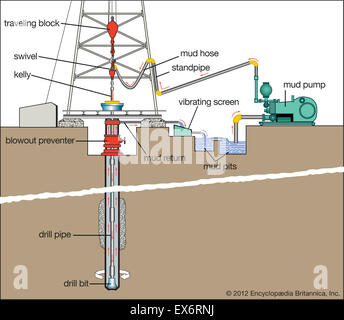
The rig’s circulation system consists of several components. Together, they methodically and efficiently deliver drilling fluids into the wellbore throughout the drilling process. Drilling fluids serve a number of purposes, as we will see.
Drilling fluid, which drillers call “mud”, can be petroleum based, water based, composed of synthetic oil and even pneumatic, such as foams. Drilling fluids can also contain additional solids to obtain the desired density, thickness, viscosity and other properties. Regardless of their chemical composition, however, drilling fluids serve several functions.
First, as the fluid is pumped through the drill bit, it provides the hydraulic energy to operate the drill bit and other downhole tools. In so doing, the fluid also serves to cool and lubricate the drill bit.
As the bit drills the well, it grinds the solid rock into rubble called “cuttings”. The circulating drilling fluid carries these cuttings from the bottom of the well to the surface.
Finally, thousands of feet of drilling fluid in a wellbore amounts to a considerable weight. This weight is important for the fourth major function of drilling fluids – to provide weight to counterbalance any tendency of the oil or gas to flow to the surface. Such an uncontrolled release in a live wellbore drilled conventionally can be quite hazardous. Consequently, this is a vital function of the drilling fluid.
The mud pump is the heart of a rig’s circulating system. These devices are large reciprocating pumps which force the fluid from the mud tanks, up a standpipe, and through a high-pressure hose.
This flexible, high-pressure hose connects the standpipe to the swivel, allowing for vertical movement in the derrick. Through the hose, fluid is pumped into the drillstring.
The drill string conveys the mud through the blowout preventer and down the wellbore to the drill bit. The fluid flows through the drillstring and out the drill bit nozzles at the bottom of the well. The return fluid path is through the annulus between the drill string and the borehole. Upon reaching surface, the fluid, now laden with rock cuttings from the bottom of the well, moves to mud-cleaning equipment and shale shakers.
As the name implies, shale shakers shake! These machines have for decades been the first line of defense in eliminating cuttings from the drilling fluid. Eliminating cuttings, also called “drilled solids” is critical to maintain an efficient drilling process.
Shakers are equipped with fine-mesh screens that allow fluid to pass through without the drilled cuttings. The shakers separate the rock cuttings from the fluid, allowing the often-costly drilling fluid to be recycled and re-used in the well, while isolating rock cuttings for proper disposal. Hydrocyclones, mud cleaners and centrifuges might also be used to remove additional solids returned from the sub-surface.


 8613371530291