
mud pump drilling operation free sample

I’ve run into several instances of insufficient suction stabilization on rigs where a “standpipe” is installed off the suction manifold. The thought behind this design was to create a gas-over-fluid column for the reciprocating pump and eliminate cavitation.
When the standpipe is installed on the suction manifold’s deadhead side, there’s little opportunity to get fluid into all the cylinders to prevent cavitation. Also, the reciprocating pump and charge pump are not isolated.
The gas over fluid internal systems has limitations too. The standpipe loses compression due to gas being consumed by the drilling fluid. In the absence of gas, the standpipe becomes virtually defunct because gravity (14.7 psi) is the only force driving the cylinders’ fluid. Also, gas is rarely replenished or charged in the standpipe.
The suction stabilizer’s compressible feature is designed to absorb the negative energies and promote smooth fluid flow. As a result, pump isolation is achieved between the charge pump and the reciprocating pump.
The isolation eliminates pump chatter, and because the reciprocating pump’s negative energies never reach the charge pump, the pump’s expendable life is extended.
Investing in suction stabilizers will ensure your pumps operate consistently and efficiently. They can also prevent most challenges related to pressure surges or pulsations in the most difficult piping environments.
Sigma Drilling Technologies’ Charge Free Suction Stabilizer is recommended for installation. If rigs have gas-charged cartridges installed in the suction stabilizers on the rig, another suggested upgrade is the Charge Free Conversion Kits.

There are many different ways to drill a domestic water well. One is what we call the “mud rotary” method. Whether or not this is the desired and/or best method for drilling your well is something more fully explained in this brief summary.
One advantage of drilling with compressed air is that it can tell you when you have encountered groundwater and gives you an indication how much water the borehole is producing. When drilling with water using the mud rotary method, the driller must rely on his interpretation of the borehole cuttings and any changes he can observe in the recirculating fluid. Mud rotary drillers can also use borehole geophysical tools to interpret which zones might be productive enough for your water well.
The mud rotary well drilling method is considered a closed-loop system. That is, the mud is cleaned of its cuttings and then is recirculated back down the borehole. Referring to this drilling method as “mud” is a misnomer, but it is one that has stuck with the industry for many years and most people understand what the term actually means.
The water is carefully mixed with a product that should not be called mud because it is a highly refined and formulated clay product—bentonite. It is added, mixed, and carefully monitored throughout the well drilling process.
The purpose of using a bentonite additive to the water is to form a thin film on the walls of the borehole to seal it and prevent water losses while drilling. This film also helps support the borehole wall from sluffing or caving in because of the hydraulic pressure of the bentonite mixture pressing against it. The objective of the fluid mixture is to carry cuttings from the bottom of the borehole up to the surface, where they drop out or are filtered out of the fluid, so it can be pumped back down the borehole again.
When using the mud rotary method, the driller must have a sump, a tank, or a small pond to hold a few thousand gallons of recirculating fluid. If they can’t dig sumps or small ponds, they must have a mud processing piece of equipment that mechanically screens and removes the sands and gravels from the mixture. This device is called a “shale shaker.”
The driller does not want to pump fine sand through the pump and back down the borehole. To avoid that, the shale shaker uses vibrating screens of various sizes and desanding cones to drop the sand out of the fluid as it flows through the shaker—so that the fluid can be used again.
Before the well casing and screens are lowered into the borehole, the recirculating fluid is slowly thinned out by adding fresh water as the fluid no longer needs to support sand and gravel. The driller will typically circulate the drilling from the bottom up the borehole while adding clear water to thin down the viscosity or thickness of the fluid. Once the fluid is sufficiently thinned, the casing and screens are installed and the annular space is gravel packed.
Gravel pack installed between the borehole walls and the outside of the well casing acts like a filter to keep sand out and maintain the borehole walls over time. During gravel packing of the well, the thin layer of bentonite clay that kept the borehole wall from leaking drilling fluid water out of the recirculating system now keeps the formation water from entering the well.
Some drillers use compressed air to blow off the well, starting at the first screened interval and slowly working their way to the bottom—blowing off all the water standing above the drill pipe and allowing it to recover, and repeating this until the water blown from the well is free of sand and relatively clean. If after repeated cycles of airlift pumping and recovery the driller cannot find any sand in the water, it is time to install a well development pump.
Additional development of the well can be done with a development pump that may be of a higher capacity than what the final installation pump will be. Just as with cycles of airlift pumping of the well, the development pump will be cycled at different flow rates until the maximum capacity of the well can be determined. If the development pump can be operated briefly at a flow rate 50% greater than the permanent pump, the well should not pump sand.
Mud rotary well drillers for decades have found ways to make this particular system work to drill and construct domestic water wells. In some areas, it’s the ideal method to use because of the geologic formations there, while other areas of the country favor air rotary methods.
Some drilling rigs are equipped to drill using either method, so the contractor must make the decision as to which method works best in your area, for your well, and at your point in time.
To learn more about the difference between mud rotary drilling and air rotary drilling, click the video below. The video is part of our “NGWA: Industry Connected” YouTube series:
Gary Hix is a Registered Professional Geologist in Arizona, specializing in hydrogeology. He was the 2019 William A. McEllhiney Distinguished Lecturer for The Groundwater Foundation. He is a former licensed water well drilling contractor and remains actively involved in the National Ground Water Association and Arizona Water Well Association.

The 2,200-hp mud pump for offshore applications is a single-acting reciprocating triplex mud pump designed for high fluid flow rates, even at low operating speeds, and with a long stroke design. These features reduce the number of load reversals in critical components and increase the life of fluid end parts.
The pump’s critical components are strategically placed to make maintenance and inspection far easier and safer. The two-piece, quick-release piston rod lets you remove the piston without disturbing the liner, minimizing downtime when you’re replacing fluid parts.
When choosing a size and type of mud pump for your drilling project, there are several factors to consider. These would include not only cost and size of pump that best fits your drilling rig, but also the diameter, depth and hole conditions you are drilling through. I know that this sounds like a lot to consider, but if you are set up the right way before the job starts, you will thank me later.
Recommended practice is to maintain a minimum of 100 to 150 feet per minute of uphole velocity for drill cuttings. Larger diameter wells for irrigation, agriculture or municipalities may violate this rule, because it may not be economically feasible to pump this much mud for the job. Uphole velocity is determined by the flow rate of the mud system, diameter of the borehole and the diameter of the drill pipe. There are many tools, including handbooks, rule of thumb, slide rule calculators and now apps on your handheld device, to calculate velocity. It is always good to remember the time it takes to get the cuttings off the bottom of the well. If you are drilling at 200 feet, then a 100-foot-per-minute velocity means that it would take two minutes to get the cuttings out of the hole. This is always a good reminder of what you are drilling through and how long ago it was that you drilled it. Ground conditions and rock formations are ever changing as you go deeper. Wouldn’t it be nice if they all remained the same?
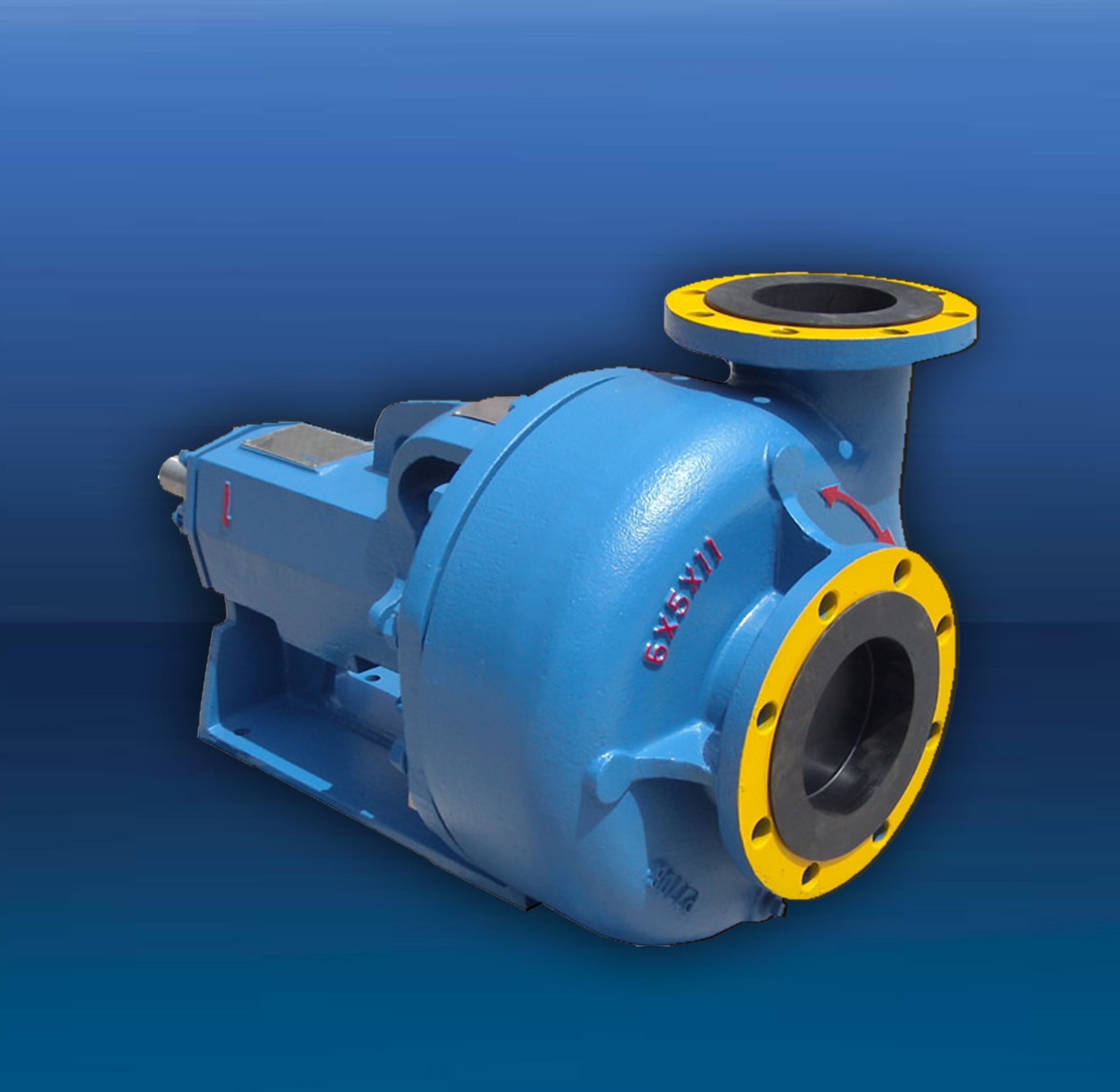
Centrifugal-style mud pumps are very popular in our industry due to their size and weight, as well as flow rate capacity for an affordable price. There are many models and brands out there, and most of them are very good value. How does a centrifugal mud pump work? The rotation of the impeller accelerates the fluid into the volute or diffuser chamber. The added energy from the acceleration increases the velocity and pressure of the fluid. These pumps are known to be very inefficient. This means that it takes more energy to increase the flow and pressure of the fluid when compared to a piston-style pump. However, you have a significant advantage in flow rates from a centrifugal pump versus a piston pump. If you are drilling deeper wells with heavier cuttings, you will be forced at some point to use a piston-style mud pump. They have much higher efficiencies in transferring the input energy into flow and pressure, therefore resulting in much higher pressure capabilities.
Piston-style mud pumps utilize a piston or plunger that travels back and forth in a chamber known as a cylinder. These pumps are also called “positive displacement” pumps because they literally push the fluid forward. This fluid builds up pressure and forces a spring-loaded valve to open and allow the fluid to escape into the discharge piping of the pump and then down the borehole. Since the expansion process is much smaller (almost insignificant) compared to a centrifugal pump, there is much lower energy loss. Plunger-style pumps can develop upwards of 15,000 psi for well treatments and hydraulic fracturing. Centrifugal pumps, in comparison, usually operate below 300 psi. If you are comparing most drilling pumps, centrifugal pumps operate from 60 to 125 psi and piston pumps operate around 150 to 300 psi. There are many exceptions and special applications for drilling, but these numbers should cover 80 percent of all equipment operating out there.
The restriction of putting a piston-style mud pump onto drilling rigs has always been the physical size and weight to provide adequate flow and pressure to your drilling fluid. Because of this, the industry needed a new solution to this age-old issue.
As the senior design engineer for Ingersoll-Rand’s Deephole Drilling Business Unit, I had the distinct pleasure of working with him and incorporating his Centerline Mud Pump into our drilling rig platforms.
In the late ’90s — and perhaps even earlier — Ingersoll-Rand had tried several times to develop a hydraulic-driven mud pump that would last an acceptable life- and duty-cycle for a well drilling contractor. With all of our resources and design wisdom, we were unable to solve this problem. Not only did Miller provide a solution, thus saving the size and weight of a typical gear-driven mud pump, he also provided a new offering — a mono-cylinder mud pump. This double-acting piston pump provided as much mud flow and pressure as a standard 5 X 6 duplex pump with incredible size and weight savings.
The true innovation was providing the well driller a solution for their mud pump requirements that was the right size and weight to integrate into both existing and new drilling rigs. Regardless of drill rig manufacturer and hydraulic system design, Centerline has provided a mud pump integration on hundreds of customer’s drilling rigs. Both mono-cylinder and duplex-cylinder pumps can fit nicely on the deck, across the frame or even be configured for under-deck mounting. This would not be possible with conventional mud pump designs.
The second generation design for the Centerline Mud Pump is expected later this year, and I believe it will be a true game changer for this industry. It also will open up the application to many other industries that require a heavier-duty cycle for a piston pump application.

Instead of using paper checklists when out in the field, drilling contractors and rig inspection services can generate a new inspection form from anywhere and the results are saved electronically.
Specifically designed for drilling companies and others in the oil and gas industry, the easy to use drilling rig inspections app makes it easy to log information about the drill rigs, including details about the drill rigs operators, miles logged and well numbers. The inspection form app covers everything from the mud pump areas and mud mixing area to the mud tanks and pits, making it easy to identify areas where preventative maintenance is needed. The drilling rig equipment checklist also covers health and safety issues, including the availability of PPE equipment, emergency response and preparedness processes, and other critical elements of the drilling process and drill press equipment.

The principal component of a rotary, or rotary machine, used to turn the drill stem and support the drilling assembly. It has a beveled gear arrangement to create the rotational motion and an opening into which bushings are fitted to drive and support the drilling assembly.
A hole in the rig floor 30 to 35 feet deep, lined with casing that projects above the floor. The kelly is placed in the rathole when hoisting operations are in progress.†
The cutting or boring element used in drilling oil and gas wells. Most bits used in rotary drilling are roller-cone bits. The bit consists of the cutting elements and the circulating element. The circulating element permits the passage of drilling fluid and uses the hydraulic force of the fluid stream to improve drilling rates.†
The heavy seamless tubing used to rotate the bit and circulate the drilling fluid. Joints of pipe 30 feet long are coupled together with tool joints.†

Drilling mud is most commonly used in the process of drilling boreholes for a variety of reasons such as oil and gas extraction as well as core sampling. The mud plays an important role in the drilling process by serving numerous functions. The main function it is utilized for is as a lubricating agent. A large amount of friction is generated as drilling occurs which has the potential to damage the drill or the formation being drilled. The mud aids in the decrease in friction as well as lowering the heat of the drilling. It also acts a carrier for the drilled material so it becomes suspended in the mud and carried to the surface.
Using a Moyno progressive cavity pump, the drilling mud with suspended material can be pumped through a process to remove the solids and reuse the cleaned mud for further drilling.
If you ended up on this page doing normal allowed operations, please contact our support at support@mdpi.com. Please include what you were doing when this page came up and the Ray ID & Your IP found at the

For sustainable development of the mineral resources in the Arctic offshore, it is necessary to develop and implement efficient technologies that are suitable for Arctic conditions and safe from an environmental point of view. The construction of oil and gas wells offshore comes with certain problems that hinder efficiency and increase the cost of drilling operations. One of the main challenges before the drilling process is selecting the optimal drilling fluid, which depends on geological conditions, formation pressure, and absorption pressures. It is also necessary to note the system’s ability to preserve the reservoir properties of the productive formation, ensure wellbore stability and integrity; include high zenith angles during the entire drilling interval until its casing; and higher drilling speeds through various sedimentary rocks, such as shale, clay shale, and limestone, etc.
The drilling process is often complicated by the integrity of the borehole walls being compromised by unstable clay deposits (clays, shales, and mudstones). This can result in cavings, rockfalls, borehole constriction, and cavern formation, with cavings becoming more likely with the increase in depth and inclination angle. The increased danger of cavings is caused by the collapse of weakly cemented siltstones and mudstones, which are in contact with solution filtrate; and by plastic flow of montmorillonite clays during osmotic swelling [1]. In order to prevent and eliminate these complications, it is recommended to weight the drilling mud or use systems with low water loss. However, worldwide experience in offshore drilling has shown that such actions do not fully exclude borehole stability disruption [2].
The drilling of easily swollen clays disperses them and produces an increased amount of colloidal particles, resulting in complications, such as pinches, landings, sticking, packing, and reduced efficiency of the flushing system. Consequently, when selecting drilling fluids for drilling in caving zones, the density and water loss of the flushing fluid are not the determining factors. Under these conditions, the choice should be made in favor of the most inert drilling system in contact with unstable formations [3,4].
In order to improve the quality of drilling-in the formation, the solution must be designed to reduce the natural permeability of the productive interval slightly or not at all, in order to provide excellent borehole cleaning and to facilitate further development of the well [5,6]. In addition to being safe and economical to use, drilling-in solutions must be compatible with natural fluids to avoid salt deposition or emulsion formation [1,7]. A suitable non-polluting fluid should form a filter cake on the formation surface, but should not penetrate too deeply into its pore section. The mud filtrate should also prevent swelling of active clay particles within the pore base [8].
When constructing wells in the Arctic offshore, it is advisable to opt for environmentally safe drilling fluids. One of the criteria for the safety of reagents for offshore drilling is the HCMS (Harmonised Mandatory Control Scheme), developed within the framework of the international Oslo–Paris agreement in 2002 [9,10,11]. This assessment is carried out to determine the possible environmental impact of a chemical release at sea in the event of an accident or spill [12]. The research is based on controlling ocean algae growth inhibition and biodegradability in seawater. Only those reagents that pass safety testing are eligible for use in drilling fluids used in offshore drilling and especially under Arctic conditions [13,14].
The drilling of oil and gas wells under offshore conditions has a special focus on the disposal of drilling sludge, which has a negative impact on the environment. Environmental pollution is much greater with the use of hydrocarbon drilling systems than with water-based muds [9,15,16]. Drilling sludge is a mixture of drilling mud and drill cuttings, which, on contact, adsorb on the surface various components of the drilling mud and, as such, remain on the drilling site for a long time, in particular, in sludge pits [17,18].
All of the above-mentioned complications of offshore drilling increase the cost of drilling operations in the Arctic shelf environment. Therefore, search, development, and improvement of environmentally safe drilling muds on the water basis, containing different additives that could give properties similar to those of solutions on the hydrocarbon base, without negative influence on the environment, is a very urgent task.
Existing drilling fluid systems are divided into water-based fluids (WBF), hydrocarbon-based fluids (HBF) and synthetic-based fluids (SBF), and gaseous systems. Factors such as cost, technical characteristics, and environmental impact have a major influence on the choice of solution [19].
The most environmentally friendly are the aqueous solutions that use environmentally friendly materials: Biodegradable polysaccharides, their esters, and clay powders. Particular attention must be paid to the clay inhibitors, surfactants, and lubricating additives required for accident-free operation when using such solutions [9].
A drilling-fluid system is a component of the well construction process that remains in contact with the wellbore throughout the drilling operation. The design of the drilling-fluid system involves the development of its formulation and is carried out so as to perform effectively under the expected conditions in the wellbore [20]. The main functions of drilling fluids and their corresponding properties are shown in Table 1.
In addition to the functions described above, drilling fluids should be selected in such a way as to improve efficiency and safety during the drilling process.
The aim of the work is to develop, improve, and study compositions of weighted drilling muds with low solid content based on organic salts of alkali metals and polymers for the construction of wells prone to rock swelling and/or caving, as well as for drilling muds for productive drilling-in the formation.

Cavitation is an undesirable condition that reduces pump efficiency and leads to excessive wear and damage to pump components. Factors that can contribute to cavitation, such as fluid velocity and pressure, can sometimes be attributed to an inadequate mud system design and/or the diminishing performance of the mud pump’s feed system.
When a mud pump has entered full cavitation, rig crews and field service technicians will see the equipment shaking and hear the pump “knocking,” which typically sounds like marbles and stones being thrown around inside the equipment. However, the process of cavitation starts long before audible signs reveal themselves – hence the name “the silent killer.”
Mild cavitation begins to occur when the mud pump is starved for fluid. While the pump itself may not be making noise, damage is still being done to the internal components of the fluid end. In the early stages, cavitation can damage a pump’s module, piston and valve assembly.
The imperceptible but intense shock waves generated by cavitation travel directly from the fluid end to the pump’s power end, causing premature vibrational damage to the crosshead slides. The vibrations are then passed onto the shaft, bull gear and into the main bearings.
If not corrected, the vibrations caused by cavitation will work their way directly to critical power end components, which will result in the premature failure of the mud pump. A busted mud pump means expensive downtime and repair costs.
To stop cavitation before it starts, install and tune high-speed pressure sensors on the mud suction line set to sound an alarm if the pressure falls below 30 psi.
Although the pump may not be knocking loudly when cavitation first presents, regular inspections by a properly trained field technician may be able to detect moderate vibrations and slight knocking sounds.
Gardner Denver offers Pump University, a mobile classroom that travels to facilities and/or drilling rigs and trains rig crews on best practices for pumping equipment maintenance.
Severe cavitation will drastically decrease module life and will eventually lead to catastrophic pump failure. Along with downtime and repair costs, the failure of the drilling pump can also cause damage to the suction and discharge piping.
When a mud pump has entered full cavitation, rig crews and field service technicians will see the equipment shaking and hear the pump ‘knocking’… However, the process of cavitation starts long before audible signs reveal themselves – hence the name ‘the silent killer.’In 2017, a leading North American drilling contractor was encountering chronic mud system issues on multiple rigs. The contractor engaged in more than 25 premature module washes in one year and suffered a major power-end failure.
Gardner Denver’s engineering team spent time on the contractor’s rigs, observing the pumps during operation and surveying the mud system’s design and configuration.
The engineering team discovered that the suction systems were undersized, feed lines were too small and there was no dampening on the suction side of the pump.
Following the implementation of these recommendations, the contractor saw significant performance improvements from the drilling pumps. Consumables life was extended significantly, and module washes were reduced by nearly 85%.
Although pump age does not affect its susceptibility to cavitation, the age of the rig can. An older rig’s mud systems may not be equipped for the way pumps are run today – at maximum horsepower.
It may be impractical to flush system piping during drilling operations. However, strainer screens should be checked daily to remove any debris or other flow restrictions.


 8613371530291