
mud pump energy multiplier factory

Centerline Manufacturing is committed to the highest level of customer service quality. Every Centerline pump is comprehensively and repeatedly tested at diverse pressure levels to assure that it goes to our customer in perfect operational order. Centerline technicians work to ensure that our customers fully understand the operation of the model being delivered. If a customer"s pump is down, we understand the importance of timely response and parts availability. Centerline technicians will assess the problem and make repairs to bring the pump back into new specification. The Centerline mud pump technicians are well versed and qualified to operate and repair any product that is provided to the customer.

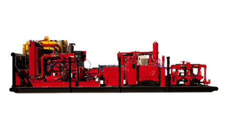
The 2,200-hp mud pump for offshore applications is a single-acting reciprocating triplex mud pump designed for high fluid flow rates, even at low operating speeds, and with a long stroke design. These features reduce the number of load reversals in critical components and increase the life of fluid end parts.
The pump’s critical components are strategically placed to make maintenance and inspection far easier and safer. The two-piece, quick-release piston rod lets you remove the piston without disturbing the liner, minimizing downtime when you’re replacing fluid parts.

For the successful execution of your projects, it is important to find an appropriate company with a good track record. We help you in connecting with the top mud pump manufacturers and companies and get the best quotation.
We have designed affordable annual subscription plans which would help you get leads for your business. You can have a look at our pricing chart by clicking on this link: https://www.energydais.com/pricing/ . These plans are customized according to the specific needs and requirements of your business.
The most widely used mud pumps across the industry are Triplex Reciprocating Pumps. Their application has gained immense popularity with time because they are 30% lighter than duplex reciprocating pumps with relatively less operational cost. Moreover, through these pumps the discharge of mud is smooth and they are capable of moving large volume of mud at higher pressure.
Yes. We help you find the best mud pumps irrespective of your location. We simplify your search by connecting you with top mud pump manufacturers and mud pump companies in your location, according to your budget and business requirement.
The most widely used mud pumps across the industry are Triplex Reciprocating Pumps. Their application has gained immense popularity with time because they are 30% lighter than duplex reciprocating pumps with relatively less operational cost. Moreover, through these pumps the discharge of mud is smooth and they are capable of moving large volume of mud at higher pressure.
The different parts of a mud pump are Housing itself, Liner with packing, Cover plus packing, Piston and piston rod, Suction valve and discharge valve with their seats, Stuffing box (only in double-acting pumps), Gland (only in double-acting pumps), and Pulsation dampener. A mud pump also includes mud pump liner, mud pump piston, modules, hydraulic seat pullers along with other parts.
The wearing parts of a mud pump should be checked frequently for repairing needs or replacement. The wearing parts include pump casing, bearings, impeller, piston, liner, etc. Advanced anti-wear measures should be taken up to enhance the service life of the wearing parts. This can effectively bring down the project costs and improve production efficiency.

Editor’s Note: The following is the statement given on June 26 by Jared Blong, CEO and President of Octane Energy LLC, before the United States House of Representatives’ Small Business Subcommittee on Agriculture, Energy, and Trade:
Chairman Tipton, Ranking Member Murphy, and members of the Subcommittee, my name is Jared Blong. I serve as the chief executive officer and president of Octane Energy, a Midland, Texas-based small business that provides oil field services support to oil and gas exploration companies. It’s an honor to address you today on the critical subject of crude oil exports.
Octane Energy is truly a small business. The company was founded in 2013 in response to the energy renaissance our country is experiencing. Projected sales this fiscal year are $3.5 million. Octane has 12 staff, of which 50 percent are veterans of the American forces and we hope to double in size over the next 12 months. Octane currently provides project management on eight oil and gas rigs for seven operators.
Today, I have the privilege of speaking to you not as a representative of a special interest group or research firm, but instead from the perspective of a small business owner from the heartland of the American energy industry. And while we will cite a number of independent studies that have recently been conducted and that are available to the public on this topic, I can offer you something that I believe is even more valuable—perspective and experience from a small business owner who could very well succeed or fail based on the policies you adopt.
Today, America is undergoing a resurgence in oil and natural gas production. Consider the following:The US has now surpassed Saudi Arabia and Russia as the world’s largest producer of oil and natural gas, according to the United States Energy Information Administration. In just one year, U.S. oil output jumped by 1 million barrels per day—the largest rate of increase in U.S. history.
By every measure, the United States is less reliant on foreign sources of energy than ever before: total U.S. net imports of energy declined 19% from 2012 to 2013, hitting the lowest level in more than 20 years, according to the United States Energy Information Administration.
While some may think that this growth can be attributed exclusively to the “majors”—that is, the larger, independent or integrated oil and gas companies—let me suggest that the vast majority of the nearly 10 million Americans who work in the energy sector are small business entrepreneurs like me, dedicated to conservation, innovation, efficiency, and stewardship—and our contributions are, and will continue to be, instrumental to America’s energy future. According to the Financial Times, “The Shale Revolution… has been the energy industry’s equivalent of the dotcom revolution, with Texas and Oklahoma standing in for Silicon Valley, and Exxon as IBM.” The companies at the leading edge of this revolution range in size from companies like Octane to companies like Concho Resources or Pioneer Natural Resources, two of the Permian Basin’s largest independent producers. In fact, in the Permian Basin, only one of the top eight most active producers, which only represent 42 percent of the basin’s market from a rig activity perspective, is considered a major.
Our company, Octane Energy, is an oil field service provider and we are on the front lines of the energy resurgence. As technology continues to advance and new supplies of crude oil are discovered or rediscovered, as in the case of the Permian Basin where we are headquartered, I see firsthand how this renaissance in oil and natural gas has positively impacted jobs, how it has created greater sustainability in a historically cyclical business, and how it is helping to achieve energy security for our country.
But I also see unnecessary hurdles that could limit the opportunities for U.S. businesses. For instance, the 1970s-era policy banning oil exports—a remnant of a price controls system that ended in 1981—is creating growing market distortions and needs to be revisited in light of rising U.S. oil production and the expanded domestic resource potential. This policy prevents our small business and others from growing as we otherwise could, prevents us from creating jobs as we otherwise could, and most importantly prevents our country from being energy secure as it otherwise could.
First, I should state that my business, like so many other small businesses involved with the energy industry, is directly impacted by the rig count—that is, by the number of rigs that are actively drilling for oil and gas in the United States. When more rigs are drilling here in the United States (i.e. when the rig count goes up) so too does the number of people that I can employ, as a general rule. In addition to simply adding numbers to our team of people, the quality of jobs is also notable. For Octane’s consulting practice, we can conceivably add up to four Well Site Leaders per rig at a typical remuneration of $220,000 per year per team member. We are also in the process of establishing a drilling company. Based on our rig design and management philosophy, we will require up to 25 employees per rig, with an average annual pay of $76,000 per employee. Many of these folks we seek to employ are American veterans who possess small unit leadership skills and an intrinsic appreciation for teamwork, process, sweat, and rigid operating procedures that are crucial to exceeding mission objectives in the energy industry. Lifting the ban on oil exports would ensure the sustainability of these well-paying jobs in our company and other companies in the industry. The same goes for catering companies that feed rig hands, for steel manufacturers that make drill pipe, for technology companies that make wireline downhole sensors, and for countless other businesses that take part in energy exploration and production.
Creating a sustainable increased rig count is directly tied to lifting the export ban and will facilitate Octane Energy’s direct investment in the manufacturing of an American rig fleet, which will create secondary and tertiary sustained job growth. Increased rig construction will contribute to growth from the financial/investment sector, all the way through the pipeline of the energy sector and into transportation and manufacturing, with lasting systemic effect for our economy. And ultimately, as we create jobs and grow businesses, we create additional tax revenue, as cited in the IHS study.
Construction of an Octane Rig will create jobs in New York for the production of shale shakers, Ohio for the manufacture of mud pumps, and various locations in Texas for drill pipe, automation, and iron, just to name a few.
Now, not only do these studies find that jobs in the energy sector would be impacted, but these studies (as well as others not funded by the oil industry) each predict that lifting the crude export ban is likely to lower gasoline prices for U.S. consumers. IHS states: “By boosting global supplies, the elimination of the ban will result in lower global oil prices. Since U.S. gasoline is priced off global gasoline prices, not domestic crude prices, the reduction will flow back into lower prices at the pump—reducing the gasoline price 8 cents a gallon. The savings for motorists is $265 billion over the 2016-2030 period.”
I believe, as many do, that America has entered a new era of energy stewardship. In years past, we were limited in the production of oil and natural gas simply because we didn’t have the know-how to produce more. But through technological breakthroughs in precision drilling and completions techniques, we can develop resources previously thought unreachable, unattainable, and uneconomic. And we can do so while maintaining the highest degree of environmental stewardship, safety, and community compassion. Bottom line: the United States energy industry is consistently producing more oil and natural gas per well than ever before.
The fact is, America now counts its oil and natural gas supply in centuries. This renaissance in U.S. energy production is in contrast to the popular belief of just ten years ago that our nation was running out of oil and natural gas. In fact, that outlook then drove the U.S. refining industry to invest tens of billions of dollars to retool refineries to process heavy, high-sulfur bitumen and oil sands from South America, Canada, and Saudi Arabia, because the prominent thought was that we would run out of the type of oil native to the United States. We now find ourselves in a much different position, due to the shale revolution, and have more light, sweet American crude than we can refine with the current infrastructure of our refineries.
Over the years, some have argued granting U.S. crude oil producers free access to world markets would drive up the cost of gasoline and other petroleum products for American consumers. The opposite is actually true. By imposing trade restrictions on a single segment of the energy industry, namely domestically produced crude (WTI), our government is arbitrarily discounting American raw material to for U.S. refineries—many of which are foreign-owned—because of a simple mismatch of supply and demand. American energy producers are sending more crude to the refinery than can be accommodated, thereby driving down the price of domestically produced crude (WTI), which should lower gasoline prices at the pump—except our gasoline and refined product prices are set globally and not on a domestic basis. Refineries are buying American crude at a discounted rate, relative to the global market, but then selling refined petroleum products at a higher, globally traded rate. The increased net gains of the refineries are not trickling back to energy producers and service companies, or even to the American consumer.
America’s energy renaissance is in jeopardy. In my opinion, these outdated crude export restrictions have prevented domestic oil exploration and production from achieving its full potential—slowing job growth, restricting supply, and negatively affecting global refined product balances, which sends the wrong message to our trading partners around the world. The shale revolution has led to an excess supply of light crude oil in the United States. However, U.S. refineries are better suited to process heavy crude oil, while refineries in other countries are better suited to process light crude oil. The ban on U.S. crude oil exports creates an inefficient distribution of crude oil among refineries in the Western Hemisphere and elsewhere in the world. I’m not the only one who believes this. The study I cited above by Resources for the Future states: “Lifting the ban on U.S. crude oil exports would allow for a more efficient distribution of crude oil among refineries in the Western Hemisphere and elsewhere in the world. A better allocation of refinery activity will result in more gasoline production, which will lower gasoline prices.”
The true benefit to the American consumer will be competition for the refining of gasoline. Indeed, crude oil is no different than any other commodity, product, or service demanded by consumers. Lower prices are only brought about by increased supply, greater competition amongst sellers, weaker demand, or improved efficiency in the manufacturing and distribution process. When governments attempt to legislate lower prices through regulations, no matter how well-meaning the laws may be when introduced, market distortions and unintended consequences inevitably result; supply and competition among producers is rendered short of potential, and the consumer ends up paying higher prices at the gas pump and in their monthly energy bills.
America is at a crossroads. Do we cap oil production or allow exports? Lifting export restrictions will strengthen our domestic oil industry, a critical component of our economy whose impact reaches far beyond the American consumer. At a time when unemployment sits at nearly 7 percent and first quarter 2014 GDP is in negative territory, the energy sector has added jobs for millions of Americans—both directly and indirectly through energy service and equipment companies. In fact, the unemployment rate in the Permian Basin is currently 2.3 percent and has been below 4 percent for the last half decade. It has also served as a job multiplier for our nation’s growing chemical and manufacturing industries. Another recent IHS report issued in September 2013 on unconventional oil and gas—or oil and gas produced by horizontal drilling—found that:Employment attributed to unconventional oil and gas and petrochemical activity currently supports more than 2.1 million jobs. IHS projects it to grow to 3.3 million jobs by 2020 and 3.9 million jobs by 2025
Unconventional energy increased U.S. household disposable income by $1,200 in 2012. IHS projects the contribution to increase to $2,000 per household in 2015 and $3,500 per household in 2025.
Unconventional energy activity and employment contributed more than $74 billion in government revenues in 2012 and is projected to increase to $138 billion per year in 2025.
Beyond its economic benefits, supporting domestic oil production is vital for our national security. Indeed, the growth in domestic oil production over the past several years has contributed to a significant drop in U.S. reliance on imported oil. But national security and oil exports are not mutually exclusive; in fact, they go hand-in-hand. Authorizing oil exports would promote investment in additional energy resource and infrastructure development at home, enabling our nation to better control its own destiny. Lifting the export ban on crude actually helps protect U.S. consumers from the roller-coaster of price shocks and geopolitically driven supply disruptions. Exporting U.S. crude strengthens our allies and diminishes the “Oil Weapon” that is brandished by oil-rich oligarchies around the globe. Additionally, exporting U.S. crude allows the United States to finally reverse 40 years of wealth transfer to OPEC by selling our domestically produced premium product on the global market.
We find ourselves at an impasse. Technological advances have increased production, such that we can now produce more oil, faster than ever before through the same well. In the drilling industry, we are rapidly reaching a time when there will be an economic cap on the rig count. By that, I mean that it will be economically unfeasible to employ more rigs in the very near future because we will easily surpass our nation’s ability to refine the increased oil per well. For my company’s part, a limit on rig count will severely limit the number of people we can employ and will thereby affect the broader scope of employment in the U.S. energy sector. A lift of the ban on oil exports would allow a natural economic response and an increased rig count in the United States because we produce light, sweet crude which could easily find a refinery on the global market.
As we currently stand, the infrastructure of domestic refineries are tooled to take heavier crude from elsewhere in the world and turn it into high-quality fuels for domestic and international use. The cost of adapting the infrastructure of these domestic refineries is so prohibitive that we cannot foresee an economic response to refining increased quantities of light, sweet crude. As small business people in the heartland of America’s energy industry, we rely on you as lawmakers to pursue lifting the ban on the export of crude oil from the United States, in an effort to avert this potential mismatch between the supplies of oil produced and the capacity of the refining sector.
I ask you to consider the course for our energy future. I think that there is a simple method. We know what we have. We know how far we have come. We must now decide how to get from here to the future. The world has changed since the OPEC oil embargo and enactment of federal regulations in the 1970s. Today, I ask you to take a stand for a fundamental principle—that the role of government is to enable its people and to remove unnecessary roadblocks that stand in the way of our national security and prosperity.
No person can travel across our country without being deeply stirred by the innovation and ingenuity of the American people—qualities that are the hallmark of America’s energy resurgence. As we enter this new chapter, it is clear that the future is bright. I do not say that all problems are solved. Far from it. But I do believe that we must stand together as faithful and wise stewards of our abundant natural resources and imagine greatly if we are to fulfil our common inheritance. The United States is our common bond and our emphasis must be not on rivalry or conflict but on cooperation, trust, and a shared vision of the future.
A neutron detector is provided herein which may include a neutron converting layer, and a scintillator layer adjacent the neutron converting layer. The neutron detector may further include a photomultiplier adjacent the scintillator layer.
A related well-logging apparatus may include a well logging tool to be conveyed within a wellbore of a subterranean formation. The well-logging tool may include a neutron converting layer, a scintillator layer adjacent the neutron converting layer, and a photomultiplier adjacent the scintillator layer. The well-logging apparatus may further include a processor coupled to the well logging tool.
A related neutron detection method may include exposing a neutron converting layer to a neutron source to cause the neutron converting layer to generate charged particles. The method may also include exposing a scintillator layer adjacent the neutron converting layer to the charged particles generated by the neutron converting layer to cause the scintillator layer to generate photons. Furthermore, the method may also include exposing a photomultiplier adjacent the scintillator layer to the photons generated by the scintillator layer to cause the photomultiplier to generate electrical pulses, and determining a neutron flux incident upon the neutron converting layer based upon the electrical pulses.
FIG. 3 is a schematic cross-sectional diagram of still another multiplier tube neutron detector in accordance with an embodiment of the present disclosure having a non-flat, hemispherical substrate.
FIG. 4 is grouping of schematic cross-sectional diagrams showing yet another multiplier tube neutron detector in accordance with embodiments of the present disclosure having a flat surface with embedded hemispherical surfaces packed either in a quadratic or hexagonal arrangement.
FIG. 5 is a schematic cross-sectional diagram showing another embodiment of the multiplier tube neutron detector of FIG. 4 and illustrating how the shape may be changed, allowing for deeper indentations.
FIG. 6 is a schematic cross-sectional diagram of another embodiment of the multiplier tube neutron detector of FIG. 4 with the application of a potential in the reactive material, by inserting an insulating layer between two layers of conductive neutron reactive materials.
FIGS. 8A-8B include perspective and end views of an alternative embodiment of the multiplier tube neutron detector in which the reactive surface is cylindrical with a “squirrel cage” photomultiplier structure.
FIG. 10 is a schematic cross-sectional diagram of an embodiment of the neutron detector of FIG. 9 including a neutron converting layer outside the vacuum tube housing of the photomultiplier and providing an entrance window to the photomultiplier.
FIG. 12 is a schematic cross-sectional diagram of another embodiment of the neutron detector of FIG. 9 in which the neutron converting layer is included within the vacuum tube housing of the photomultiplier.
FIG. 13 is a schematic cross-sectional diagram of still another embodiment of the neutron detector of FIG. 9 in which the neutron converting layer and scintillator layer are positioned outside of the vacuum tube housing of the photomultiplier.
Referring now to FIG. 1, in various embodiments, a multiplier tube neutron detector 100 includes a dynode-type electron multiplier having a series of dynodes 102 and an anode 104, a substrate 106 that functions to close the tube and maintain vacuum during operation. Furthermore, neutron-reacting material 108 (e.g., 10B, 6Li or Gd) is deposited on the substrate 106 and optionally on an extraction grid 110 to extract low energy electrons from the layer of neutron-reacting material 108. Example neutron-reacting materials include: 6Li+n→3H+4He+4780 keV σtherm=940 b
In embodiments where an extraction grid is not positioned between the neutron-reacting material and the closest dynode, the closest dynode (and associated grid) is biased positively with respect to the neutron-reacting material 108 to accelerate electrons from the neutron-reacting material 108 toward the dynode. Each successive dynode in the series of dynodes 102 is biased positively with respect to the previous dynode to provide electron multiplication typical of dynode-based electron multipliers. In various embodiments, the neutron-reacting material 108 may be at least slightly conductive so that the electrical potential between the neutron-reacting material 108 and the extraction grid 110 may be maintained.
The example illustrated in FIG. 1 is a “Venetian blind” electron multiplier structure. Each multiplication stage includes a dynode and a grid. The dynode provides the electron multiplication through secondary electron emission. The grid provides a low electric field region upstream of the dynode, and the grid from the next stage provides a high electric field region downstream of the dynode. These low and high electric fields on each side of the dynode provide the extracting force for the secondary electrons emitted at the dynode surface so that they may leave the dynode and reach the next dynode stage.
The previous material efficiencies are for a flat film of solid neutron-reacting material. The thickness of the neutron-reacting material may correspond with the range of at least one of the reaction products, so that the material will not be “dead” and retain electrons. Higher efficiencies may be realized if the film is made thicker but with an irregular (and larger) surface. For example, higher efficiency may be obtained with a micro-machined array of “posts”, each with a diameter corresponding to the neutron-reacting material thicknesses described above, so that the charged particles may escape the post and generate electrons. The length of the posts is selected to result in the detection efficiency desired for the neutron energy of interest. Longer posts may be used for epithermal neutrons since the cross section for capture of epithermal neutrons is smaller than for thermal neutrons.
Still another alternative embodiment is shown in FIG. 8, in which the detector 800 includes neutron-reacting material of a semi-cylindrical form surrounded by what is known as a “squirrel cage” photomultiplier structure. As shown in FIG. 8, the neutron-reacting material 802 is deposited on the inside surface of the tube 804. The neutron-reacting material 802 can either be a flat layer or may involve some of the previously described approaches that allow an increased surface area and therefore a larger efficiency for incident neutrons. The neutron-reacting material 802 is disposed in a semi-cylindrical form around the inside of and along the length of the tube 804. Optionally (as shown in FIG. 8), a focusing electron and grid 806 is disposed between the neutron-reacting material 802 and the series of dynodes 808 configured in a pattern that is circular when viewed from above. As with the Venetian blind style of multiplier disposed above, in this embodiment with a squirrel-cage geometry, charged particles from the neutron-reacting material 802 impinge on the first dynode in the series of dynodes 808, where, in turn, secondary electrons are generated. The secondary electrons are collected by each subsequent dynode in the way that electron multipliers conventionally operate. The charge so collected is amplified in each succeeding dynode stage in a cascade effect, so that a charge pulse is produced at the electron multiplier anode 810 that is much larger than the charge produced by the impact on the first dynode.
Turning to FIGS. 9-10 and 14, another example neutron detector 900 and related method aspects are now described. The neutron detector 900 illustratively includes a neutron converting layer or film 901, a scintillator layer or film 902 adjacent the neutron converting layer, and a photomultiplier 907 adjacent the scintillator layer. The photomultiplier 907 illustratively includes a photocathode 903, a series of dynodes 904 adjacent the photocathode, and an anode 905 adjacent a last one of the series of dynodes, as described further above.
Beginning at Block 1401 of the flow diagram 1400 of FIG. 14, the neutron converting layer 901 of the neutron detector 900 is exposed to a neutron source (e.g., in a wellbore, etc.) and generates gamma rays and electrons, at Block 1402. As the scintillator layer 902 is exposed to these charged particles, the scintillator layer in turn generates optical photons, at Block 1403. Upon exposure to the photomultiplier 907 (Block 1404), the photons cause the photocathode 903 to generate low energy electrons, and these electrons are multiplied in the stages of dynodes 904, as described above. The resulting anode current is larger than the charge produced by the neutron conversion film. The electrical charge pulses from the anode 905 may be processed to determine a neutron flux incident upon the neutron converting layer 901, at Block 1405, which concludes the method illustrated in FIG. 14 (Block 1406). More particularly, pulse processing electronics and counting electronics may be used to determine a count rate that is proportional to the neutron flux incident on the neutron-reacting material, for example.
In the configuration illustrated in FIGS. 9 and 10, the neutron converting film 901 defines a “window” for the neutron detector 900, and is positioned on an outside end of the neutron detector opposite the anode 905. The neutron converting film 901 includes a material having a relatively high neutron absorption cross section. The scintillator film 902 and photocathode 903 are incorporated within the vacuum tube housing of the photomultiplier 907. The series of multiplying dynodes 904 may be installed after the photocathode to amplify the electronic signal coming to the anode 906, as noted above. A shield 906 is included on the outside of the vacuum tube. The shield may include a material providing high gamma ray absorption to protect the inner components of the photomultiplier 907 from the gamma radiation for example, which may otherwise cause a “parasite” signal at the anode.
During operation, incident neutrons hit the neutron converting layer 901. The scintillator film 902 converts the electrons generated by the neutron converting layer 901, and potentially some of the low energy gamma rays, to light (i.e., optical photons) that enter the photocathode 903. The electrons created at the photocathode 903 are amplified by the dynodes 904 to provide the resultant current in the anode 905.
where d is the film thickness, n is atoms concentration (1/cm3), σ is cross section of neutrons absorption, NAis Avogadro"s number, and ρ is density. For electrons with the energy 20-100 keV, the free path in gadolinium is less than or equal to 50 μm. The thickness of the Gd foil used for desired neutron detection efficiency may depend on the type of Gd used (e.g., natural or enriched), but generally speaking this may be around 5 μm, and may provide an efficiency of about 10%. In addition to the converted electrons, the gamma rays with energy 79.1 keV and higher will be emitted from a Gd film.
In the present embodiment, material used for the scintillator layer 902 may be a crystal that is compatible with vacuum conditions and with materials contained in the photocathode. Crystals that are not necessarily compatible may also be used, but it may be desirable to position an additional window between the scintillator material the photocathode 903, which may decrease the efficiency to some degree. One example crystal material that has suitable compatibility for inclusion in the photomultiplier 907 is YAP (e.g., YAlO3, density 5.38 g/cm3). Another scintillator material that may provide desired operating characteristics and compatibility for use inside the vacuum tube is LuAP.
It should be mentioned that the gamma rays from neutron absorption in Gd (see table 1 above) may be detected in the scintillator film 902, although with a relatively low probability due to the small crystal volume. For example, the gamma rays with the energy 79.51 keV have a photoelectric absorption of 0.76 cm2/g and the full absorption peak for these energies is about 4% per one gamma ray (3% per one incident neutron). One may consider using the count rate in this peak as a neutron flux signal, although this peak may not be well resolved from the fluorescent peak from tungsten (69.5 keV), and these gamma rays will be present due to both neutron components (excited by one of the gamma rays from table 1) and external gamma components which have energy higher than 69.5 keV.
As such, detection of 79.51 keV gamma rays may be excluded if tungsten is used as a gamma ray shield 906. However, other materials may be used as a shield 906 and this would allow utilization of the 79.51 keV peak. Tungsten 69.5 keV fluorescent x-rays may be used to calibrate the energy response of the scintillator layer 902. An example window for the neutron signal detection is 20-40 keV, at which the gamma rays from the incident neutron will provide a relatively smaller contribution to the useful signal than the electrons. However, other configurations may also be used.
The photocathode 903 quantum efficiency may be compatible with the scintillator crystal emission spectrum to provide desired energy resolution. The multiplying dynodes 904 may have different structures and numbers of stages, as discussed further above.
The signal (anode current) will include one component caused by the neutrons, and another caused by the parasite gamma rays passing through the gamma absorbing shield material (e.g., tungsten, lead, or other material with a relatively high impedance (Z) and density). Most of these gamma rays will have a relatively high energy. Moreover, the scintillator film 902 mostly absorbs low energy gamma rays. Those gamma rays that are not absorbed by the shield 906 and which interact with the scintillator crystal layer 902 may be filtered if this signal is located in another energy range than the useful signal from the neutrons.
Gamma rays with very high energy (e.g., 500 keV) may be omitted from the total signal consideration, as there is little useful signal in this energy region. At energy values of interest for the neutron signal detection (e.g., energies of 30-60 keV, before the window around 69.5 keV, such as 65-75 keV) little external gamma ray detection is expected (even at 150 keV energy detection probability is around 2×10⁻⁷). A relatively small contribution may come from gamma rays scattered several times inside the photomultiplier 907 (e.g., in the shield 906, neutron converting film 901, etc.), which may be relatively insignificant compared to the neutron signal with around 10% detection efficiency.
In another example embodiment of the neutron detector 900′ shown in FIG. 12, the neutron converting film 901′ and scintillator film 902′ are vacuumized (i.e., included within the photomultiplier vacuum tube), and a separate entrance window or layer 908′ including a neutron transparent material (e.g., natural zirconium, etc.) is positioned on the outside end of the vacuum tube.
Referring additionally to FIG. 14, one example application for which the above-described neutron detectors may advantageously be used is for well-logging, such as for hydrocarbon resource (e.g., oil, natural gas, etc.) wells. The example shown in FIG. 14 is for a logging while drilling (LWD) or measurement while drilling (MWD) implementation, but it will be appreciated that the neutron detectors described herein may also be used in a wireline or other configuration as well in other embodiments. In the illustrated embodiment, an example configuration for acquiring well log data using an LWD/MWD system 1239 is shown. The LWD/MWD system 1239 illustratively includes one or more collar sections 1244, 1242, 1240, 1238 coupled to the lower end of a drill pipe 1220. The LWD/MWD system 1239 includes a drill bit 1245 at the bottom end to drill the wellbore 1232 through the earth 1236. In this example, drilling is performed by rotating the drill pipe 1220 using a rotary table 1243. However, drilling may also be performed by top drives and coiled tubing drilling with downhole motors, for example. During rotation, the pipe 1220 is suspended by equipment on a drill rig 1210 including a swivel 1224, which enables the pipe 1220 to rotate while maintaining a fluid tight seal between the interior and exterior of the pipe 1220. Mud pumps 1230 draw drilling fluid (“mud”) 1226 from a tank or pit 1228 and pump the mud 1226 through the interior of the pipe 1220, down through the LWD/MWD system 1239, as indicated by arrow 1241. The mud 1226 passes through orifices (not shown) in the bit 1245 to lubricate and cool the bit 1245, and to lift drill cuttings in through an annulus 1234 between the pipe 1220, LWD/MWD system 1239, and the wellbore 1232.
The LWD/MWD system 1239 may further include a mud pressure modulator (not shown separately) in one of the collar sections (e.g., the collar section 1244). The modulator applies a telemetry signal to the flow of mud 1226 inside the system 1239 and pipe 1220 where the telemetry signal is detected by a pressure sensor 1231 disposed in the mud flow system. The pressure sensor 1231 is coupled to detection equipment in a surface recording system 1250, which enables recovery and recording of information transmitted in the telemetry scheme sent by the MWD portion of the LWD/MWD system 1239. The telemetry scheme includes a subset of measurements made by the various sensors in the LWD/MWD system 1239. The telemetry of the logging tools may also be determined using a wireline cable, or electrical MWD telemetry (e.g., using electrical signals transmitted through the formation). Measurements made by the various sensors in the LWD/MWD system 1239 may also be transferred to the surface recording system 1250 when the LWD/MWD system 1239 is withdrawn from the wellbore.
Offering you a complete choice of products which include Afridev Hand Pump, Mark Ii Deepwell Hand Pump, Mark Ii Extra Deepwell Hand Pump, Vlom Mark Iii Deepwell Hand Pump, Walimi Deepwell Hand Pump and Rotary Drilling Rigs.
Rotary drilling rigs are manufactured in house with technical collaboration with salzglitter of germany. We are developing our process of manufacturing continuously and have demonstrated the same in executing various international orders in time under stringent quality norms. These drilling rigs are capable of drilling to a depths of 1000 meters and the maximum diameter of the bore hole is 24". The drilling is done in steps and depending upon the formation of the bore different types of drill bits are used for high performance of the equipment. The rigs are equipped with high powered mud pumps, water injection pumps, foam pumps to support the drilling operations. Rotary drilling is preferred in sandy soils, mud soils, clay soils and other strata where drilling with dth is not easy.
it is a double cylinder and double acting model, both downward stroke and upward stroke delivers water and optimum utilization of energy spent is achieved.
It is a universally acknowledged fact that the consumption of energy is increasing enormously and the resources to produce energy is limited and is not adequate. Fossil fuels like oil, gas, coal etc are diminishing and within a short period they will be exhausted. The time has come think about alternate sources of energy that don"t pollute the environment and the search ends with renewable energy resources.
renewable energy resources come from the sun, wind, oceans, rivers and plants. They are the oldest, cleanest and in most cases efficient forms of energy man has at his disposal. Unlike fossil fuels, such as oil and coal, these never run out and will not pollute the environment.
right now, only 8 percent of our total energy use comes from renewable energy resources. The other 92 percent are primarily made up of fossil and nuclear fuel sources. Fossil fuels have had damaging effects on the quality of our air, water and soil. In order for people to continue to live healthy lives we must increase the use of renewable energy sources.
sun energy consists of light and heat. Solar photovoltaic systems will use the light energy to produce electricity and in tern meet the load demands whereas solar thermal systems will use heat energy to increase the temperature of water stored in an insulated tank to the desired level for meeting the demand of the user.

a periodically operated pump, a source of drilling fluid, means operatively con-necting said pump to said source of drilling fluid and to said hollow drill
drop some 110 feet when 3,000 psi mud pump pressure is applied ~3,000 psi is arather typical mud pump pressure in deep wells). One can, thereforel consider


 8613371530291