
mud pump filter free sample

Explore a wide variety of filter for mud pump on Alibaba.com and enjoy exquisite deals. The machines help maintain drilling mud circulation throughout the project. There are many models and brands available, each with outstanding value. These filter for mud pump are efficient, durable, and completely waterproof. They are designed to lift water and mud with efficiency without using much energy or taking a lot of space.
The primary advantage of these filter for mud pump is that they can raise water from greater depths. With the fast-changing technology, purchase machines that come with the best technology for optimum results. They should be well adapted to the overall configuration of the installation to perform various operations. Hence, quality products are needed for more efficiency and enjoyment of the machines" full life expectancy.
Alibaba.com offers a wide selection of products with innovative features. The products are designed for a wide range of flow rates that differ by brand. They provide cost-effective options catering to different consumer needs. When choosing the right filter for mud pump for the drilling project, consider factors such as size, shape, and machine cost. More powerful tools are needed when dealing with large projects such as agriculture or irrigation.
Alibaba.com provides a wide range of filter for mud pump to suit different tastes and budgets. The site has a large assortment of products from major suppliers on the market. The products are made of durable materials to avoid corrosion and premature wear during operations. The range of products and brands on the site assures quality and good value for money.
A well-placed suction stabilizer can also prevent pump chatter. Pump chatter occurs when energy is exchanged between the quick opening and closing of the reciprocating pump’s valves and the hammer effect from the centrifugal pump. Pump isolation with suction stabilizers is achieved when the charge pumps are isolated from reciprocating pumps and vice versa. The results are a smooth flow of pumped media devoid of agitating energies present in the pumped fluid.

The O1608-16 sample pump is a low head submersible filter pump with an integral self-cleaning filter for use with on-line analyser systems and dosing pumps. It is the most popular of our smaller filterpumps for use supplying samples protecting analytical equipment.
It produces a filtered output of fluid which prevents blockage to nozzles, valves and solenoids. This Filter Pump is available in single phase, with or without float switch.
The O1608-16 combines filtering and pumping directly from the source water being sampled. It"s ease of use and installation and extremely low maintenance has made this filter pump one of our most popular products.
Fitted with 60, 115 or 300 micron filter mesh, it can be used to filter sample water on its own or as a supply to our RF100ANQ On-line Analyser filter system. Watch a video
The invention relates generally to the field of measurement while drilling systems. More specifically, the invention relates to methods for reducing the effects of noise caused by “mud” pumps on the signal channel for measurement while drilling systems that use mud flow modulation telemetry or an electromagnetic telemetry.
Measurement while drilling (“MWD”) systems and methods generally include sensors disposed in or on components that are configured to be coupled into a “drill string.” A drill string is a pipe or conduit that is used to rotate a drill bit for drilling through subsurface rock formations to create a wellbore therethrough. A typical drill string is assembled by threadedly coupling end to end a plurality of individual segments (“joints”) of drill pipe. The drill string is suspended at the Earth"s surface by a hoisting unit known as a “drilling rig.” The rig typically includes equipment that can rotate the drill string, or the drill string may include therein a motor that is operated by the flow of drilling fluid (“drilling mud”) through an interior passage in the drill string. During drilling a wellbore, some of the axial load of the drill string to the drill bit located at the bottom of the drill string. The equipment to rotate the drill string is operated and the combined action of axial force and rotation causes the drill bit to drill through the subsurface rock formations.
The drilling fluid (hereinafter “mud”) is pumped through the interior of the drill string by various types of pumps disposed on or proximate the drilling rig. The mud exits the drill string through nozzles or courses on the bit, and performs several functions in the process. One is to cool and lubricate the drill bit. Another is to provide hydrostatic pressure to prevent fluid disposed in the pore spaces of porous rock formations from entering the wellbore, and to maintain the mechanical integrity of the wellbore. The mud also lifts the drill cuttings created by the bit to the surface for treatment and disposal.
Communicating measurements made by one or more sensors in the MWD system is typically performed by the above mentioned data processor converting selected signals into a telemetry format that is applied to a valve or valve assembly disposed within a drill string component such that operation of the valve modulates the flow of drilling mud through the drill string. Modulation of the flow of drilling mud creates pressure variations in the drilling mud that are detectable at the Earth"s surface using a pressure sensor (transducer) arranged to measure pressure of the drilling mud as it is pumped into the drill string. Forms of mud flow modulation known in the art include “negative pulse” in which operation of the valve momentarily bypasses mud flow from the interior of the drill string to the annular space between the wellbore and the drill string; “positive pulse” in which operation of the valve momentarily reduces the cross-sectional area of the valve so as to increase the mud pressure, and “mud siren”, in which a rotary valve creates standing pressure waves in the drilling mud that may be converted to digital bits by appropriate phasing of the standing waves.
Irrespective of the type of mud flow modulation telemetry used, detection of the telemetry signal at the Earth"s surface may be difficult because of two principal reasons. First, while drilling mud as a liquid is relatively incompressible, it does have non-zero compressibility. Consequently, as the pressure variation travels from the valve to the surface, some of the energy therein is dissipated by compression and rarefaction of the mud as the wave traverses the drill string. Second, and more importantly, the pumps used to move the drilling mud through the drill string are very large and powerful, and frequently are of the positive displacement type. As a result, the mud pumps themselves generate large pressure variations in the mud as it is pumped through the drill string, thus masking the pressure variation signal being transmitted by the MWD instrument.
U.S. Pat. No. 6,741,185 issued to Pengyu et al. describes a method exploiting the raw pressure to estimate the parameters of the noise. The estimation is carried out in two separated tasks: the estimation of the instantaneous frequency on one side, and the estimation of other parameters on the other side via an adaptive filtering approach. U.S. Patent Application Publication No. 200710192031 submitted by Jiang Li et al. describes a similar approach using a LMS algorithm to estimate the parameters of the noise. Because both estimators are completely separated, the ability of the foregoing methods to cancel mud pump noise over a broad frequency band is limited. U.S. Pat. No. 4,642,800 issued to Umeda et al. describes a mud pump noise canceling method based on the use of a set of “stroke counters” (devices which count the operating cycles of each cylinder of the pump) to estimate the instantaneous frequency of the mud pumps. However, the estimation of the instantaneous frequency is assumed to vary linearly with the stroke counter output which is not necessarily a valid assumption.
The electromagnetic telemetry signal may likewise be masked by signal noise arising from mud pump operation. The mud pumps may create either cyclical electrical interference that mimics the repetitive activity of the mud pumps, or asynchronous noise arising from, for example, electrical interference generated by power drains caused by any sort of mechanical problem.
What is needed is more reliable methods for estimating and reducing mud pump noise for use with mud pulse telemetry and electromagnetic telemetry MWD systems.
A method according to one aspect of the invention for attenuating pump noise in a wellbore drilling system includes spectrally analyzing measurements of a parameter related to operation of a pump used to move drilling fluid through the drilling system. Synthetic spectra of the parameter are generated based on a number of pumps in the pump system and a selected number of harmonic frequencies for each pump. Which of the synthetic spectra most closely matches the spectrally analyzed parameter output is determined. The most closely matching synthetic spectrum is used to reduce noise in a signal detected proximate the Earth"s surface transmitted from a part of the drilling system disposed in a wellbore.
FIG. 1 shows an example drilling system that may use a pump noise reduction method according to the invention. FIG. 1A shows an alternative example drilling system to that illustrated in FIG. 1.
As explained in the Background section herein, drilling fluid (“drilling mud”) is pumped through the drill string 12 to perform various functions as explained above. In the present example, a tank or pit 30 may store a volume of drilling mud 32. The intake 34 of a mud pump system 36 is disposed in the tank 30 so as to withdraw mud 32 therefrom for discharge by the pump system 36 into a standpipe, coupled to a hose 26, and to certain internal components in the top drive 26 for eventual movement through the interior of the drill string 12.
The example pump system 36 shown in FIG. 1 is typical and is referred to as a “triplex” pump. The system 36 includes three cylinders 37 each of which includes therein a piston 41. Movement of the pistons 41 within the respective cylinders 37 may be effected by a motor 39 such as an electric motor. A cylinder head 40 may be coupled to the top of the cylinders 37 and may include reed valves (not shown separately) or the like to permit entry of mud into each cylinder from the intake 34 as the piston 37 moves downward, and discharge of the mud toward the standpipe as the piston 37 moves upward. Because the piston velocity is variable even at constant motor speed, the pressure in the standpipe 28 varies as the velocity of the pistons 37 changes. Typical triples pumps such as the one shown in FIG. 1 may include one or more pressure dampeners 43 coupled to the output of the pump system 36 or to the output of each cylinder to reduce the variation in pressure resulting from piston motion as explained above. In some examples, a device to count the number of movements of each piston through the respective cylinder may be coupled in some fashion to the motor or its drive output in order that the system operator can estimate the volume displaced by the pump system 36. One example is shown at 39A and is called a “stroke counter.” Such devices called stroke counters are well known in the art. It should also be noted that the invention is not limited to use with “triplex” pumps. Any number of pump elements may be used in a pump system consistently with the scope of the present invention.
As the drilling mud reaches the bottom of the drill string, it passes through various MWD instruments shown therein such as at 20, 22 and 21. One of the MWD instruments, e.g., the one at 22, may include a mud flow modulator 23 that is coupled to a controller in one of the MWD instruments to modulate the flow of drilling mud to represent signals from one or more of the MWD instruments 20, 22, 21. It should be reemphasized that “MWD” as used in the present context is intended to include “LWD” instrumentation as explained in the Background section herein. Pressure variations representative of the signals to be transmitted to the surface may be detected by one or more pressure transducers 45 coupled into the standpipe side of the drilling mud circulation system. Signals generated by the transducer(s) are communicated, such as over a signal line 44 to a recording unit 46 having therein a general purpose programmable computer 49 (or an application specific computer) to decode and interpret the pressure signals from the transducer(s) 45.
In some examples, electromagnetic telemetry may be used to communicate signals from the MWD instruments 20, 21, 22 to the surface. In such examples, the mud flow modulator may be replaced by an antenna 23A disposed in the drill string and in electrical communication with a telemetry transmitter (not shown separately) in the MWD instrumentation. Low frequency (generally up to about 25 Hz) signals are transmitted through the formations 11 where they may be detected by a surface antenna such as spaced apart electrodes 45A disposed in the ground and in communication with the computer 49 in the recording system 38. In such examples, the pump system 36 may include one or more sensors such as a current meter, Hall effect transducer, or similar device, e.g., at 39B to detect noise generated by the pump system 36.
Having explained the drilling, mud pump system and mud flow modulation telemetry system in general terms, an example mud pump noise reduction technique according to the invention will now be explained with reference to FIG. 2. The following process elements may be performed in the computer in the recording unit, or may be performed in a different computer. At 50, signals from the transducer(s) (45 in FIG. 1), and in electromagnetic telemetry examples from the sensor 39B, may be conducted to a bandpass filter, at 52 to exclude portions of the transducer/sensor signal that are unlikely to be representative of signals transmitted from the MWD instruments. The bandpass filtered signals may be conducted to one input of a summing device 66, which will be further explained below. The filtered pressure/sensor signals may also be conducted to a prediction initializer at 54. As will be further explained, a set of parameters may be initialized at the start of a pump noise signal prediction process. At 56, signals from the stroke counter (39A in FIG. 1) may be used in some examples as part of the parameter initialization. At 58, the stroke counter signals, if used, may be interpolated with respect to time to produce an approximation of certain fundamental frequency mud pump system noise signals.
After initialization, using the bandpass filtered pressure/sensor signals, a set of prediction filters is generated, as shown at 60A, 60B, 60C. For each prediction filter generated, a corresponding correction filter is generated, one such being shown at 62C that corresponds to prediction filter 60C. After generation of the correction filters, a best noise hypothesis is selected at 64. The selected best noise hypothesis is conducted to the summing device 66 to be combined with the bandpass filtered pressure signal from the transducer(s) (45 in FIG. 1). A result, at 68 is “denoised” pressure signals, that is, pressure signals with mud pump system induced noise substantially attenuated. To summarize the noise prediction/correction procedure, the following acts are performed (e.g., in the computer in the recording system). Alternatively an inverse electromagnetic noise signal may be generated and added to the signal detected by the antenna (45A in FIG. 1).
First, a selected time span of pressure data from the transducer (45 in FIG. 1) or sensor signal data (39B in FIG. 1) may be spectrally analyzed. One non-limiting example of spectral analysis is to perform a fast Fourier transform on the selected time span of pressure data. Next is to generate a set of synthetic spectra using the number of mud pumps in the pump system (36 in FIG. 1), and a selected number Mk of harmonic frequencies for the pressure signal generated by each of the pumps. The synthetic spectra may be initialized based on estimated fundamental frequencies from the stroke counter (39A in FIG. 1). Next is to adaptively filter all the foregoing synthetic spectra with a Bayesian filter approach (e.g., Kalman filters) with prediction/correction procedure. Next is to determine which synthetic spectrum most closely matches the measured spectrum (i.e., the sample of pressure data within the selected time span). Next is to synthesize a pump pressure signal from the best match synthetic spectrum. Finally, is to subtract the synthesized pump pressure signal from the pressure transducer signal. Part or all of the foregoing procedure may be repeated in the event the difference between the synthesized pump pressure signal and the measured pressure signal is greater than a selected threshold.
An explanation of the initialization, prediction filter generation, correction filter generation and best hypothesis selection follows. The harmonic structure of the noise generated by the pump system (36 in FIG. 1) can be represented by the mathematical expression:
in which M: is the number of mud pumps in the mud pump system (e.g., three as shown in the example in FIG. 1 but not limited to three); Kmis a selected number of harmonic frequencies associated with the mthpump. Such number of harmonics will depend on the characteristics of the particular pump. am,k(t) is the amplitude of the kthharmonic of the mthpump and θm,kis the initial phase of the kthharmonic of the mthpump.
One purpose of the initialization 54 is to provide an estimate of the instantaneous phase for each mud pump in the pump system. The noise attenuation process is based on automatic detection of spectral peaks with a selected harmonic relationship. The goal is to generate a set of pump output signals that have the highest probabilities to be valid fundamental frequencies of the pump noise. Based on this spectral detection, the method includes selecting a set of P frequencies that are most likely to be the fundamental frequencies of the pressure variations generated by the pump system (36 in FIG. 1).
With a set of P harmonics for M pumps, the number of unique combinations of fundamental frequencies and associated harmonics CpMis determinable by the binomial formula:
In order to analyze the entire set of selected frequencies, a number CMPof filters, for example, Kalman filters, are initialized at 54. Because of the large number of permutations in the set P of harmonics, it is preferable that the calculations are performed in parallel.
The outputs of the CpMKalman filters are sent to the best hypothesis selector 64. The best hypothesis selector 64 determines which of the Kalman filters performs the best. One criterion that can be used to determine best performance is the ratio between the energy in the estimated noise signal and the energy in the denoised signal. Once the remaining CpM−1 filters have been identified, the index of each such remaining filter is conducted to the initialization 54 whereupon the filters will be reinitialized in the next operation of the denoising procedure. As previously explained, the best noise estimate is transmitted to the summing device 66 and is combined with the transducer signal.

Heating, Ventilation and Air Conditioning Landlord shall furnish to the Premises heating, ventilation and air-conditioning (“HVAC”) in accordance with the Design Standards set forth in Exhibit D during Ordinary Business Hours. Landlord shall have access to all air-cooling, fan, ventilating and machine rooms and electrical closets and all other mechanical installations of Landlord (collectively, “Mechanical Installations”), and Tenant shall not construct partitions or other obstructions which may interfere with Landlord’s access thereto or the moving of Landlord’s equipment to and from the Mechanical Installations. No Tenant Party shall at any time enter the Mechanical Installations or tamper with, adjust, or otherwise affect such Mechanical Installations. Landlord shall not be responsible if the HVAC System fails to provide cooled or heated air, as the case may be, to the Premises in accordance with the Design Standards by reason of (i) any equipment installed by, for or on behalf of Tenant, which has an electrical load in excess of the average electrical load and human occupancy factors for the HVAC System as designed, or (ii) any rearrangement of partitioning or other Alterations made or performed by, for or on behalf of Tenant. Tenant shall install, if missing, blinds or shades on all windows, which blinds and shades shall be subject to Landlord’s approval, and shall keep operable windows in the Premises closed, and lower the blinds when necessary because of the sun’s position, whenever the HVAC System is in operation or as and when required by any Requirement. Tenant shall cooperate with Landlord and shall abide by the rules and regulations which Landlord may reasonably prescribe for the proper functioning and protection of the HVAC System. Tenant acknowledges that the server room in the Premises currently has three heat pumps installed, being two 4-ton units, and one 2.5-ton unit (the “Existing Heat Pumps”). The 2.5-ton unit is currently connected and operational. Tenant shall determine whether it is satisfied with the condition of the Existing Heat Pumps and Landlord shall not have any responsibility or liability for the condition, operation, maintenance, repair or replacement of the Existing Heat Pumps. Tenant may operate the Existing Heat Pumps. Tenant shall be responsible for, and pay directly for, all necessary maintenance and repairs to the Existing Heat Pumps. Tenant shall reimburse Landlord monthly for the cost of all utility services used to operate the Existing Heat Pumps within 10 Business Days after receipt of Landlord’s invoice for such amount. Landlord may measure Tenant’s usage of such utility services by either a sub-meter or by other reasonable methods such as by temporary check meters or by survey. Tenant, at its cost, may replace the Existing Heat Pumps with one or more new heat pumps, provided, however, that the capacity of such replacement heat pump(s) shall not exceed the 10.5-ton capacity cooling capacity of the Existing Heat Pumps.

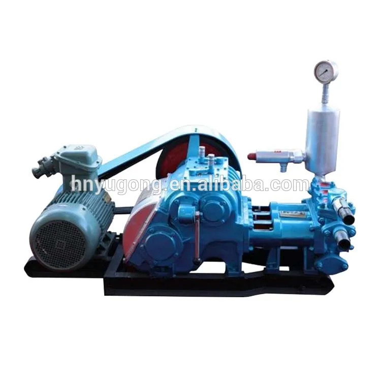
Since the NOV A1700-PT Triplex Mud Pump was built approximately 60 years ago, the industry has widely accepted the three cylinder or triplex style pump. Triplex mud pumps are manufactured worldwide, and many companies have emulated the original design and developed an improved form of the triplex pump in the past decade.
NOV A1700-PT Triplex Mud Pumps have many advantages they weight 30% less than a duplex of equal horsepower or kilowatts. The lighter weight parts are easier to handle and therefore easier to maintain. The other advantages include;They cost less to operate
One of the more important advantages of triplex over duplex pumps, is that they can move large volumes of mud at the higher pressure is required for modern deep hole drilling.
NOV A1700-PT Triplex Mud Pump is gradually phasing out duplex units. In a triplex pump, the pistons discharge mud only when they move forward in the liner. Then, when they moved back they draw in mud on the same side of the piston. Because of this, they are also called “single acting.” Single acting triplex pumps, pump mud at a relatively high speeds. NOV A1700-PT Triplex Mud Pump has three pistons each moving in its own liner. It also has three intake valves and three discharge valves. It also has a pulsation dampener in the discharge line.

API Fluid Loss Test (low-pressure, low-temperature filtration test) is a test used to measure a filtration of mud with ambient temperature and 100 psi differential pressure. The API fluid loss testing equipment is shown below (Figure 1).
If drilling fluid has good fluid loss property, it will show a thin and impermeable mud cake. Please keep in mind that this test is based on the surface condition, and it may be in error because it does not simulate downhole conditions. The API fluid loss test can lead you to the wrong conclusion, because at the surface condition the test demonstrates very good fluid loss and a very thin filter cake.When the drilling mud is in a downhole condition, wellbore temperature and pressure can dramatically change drilling fluid properties.The best way to test the fluid loss is to simulate wellbore condition at high pressure high temperature in order to see what the fluid loss property will be. The procedure is called” HTHP Fluid Loss.”
The HTHP fluid loss test is similar to the API test because it indicates information on drilling mud filtration into the formation under a static condition over a certain period of time.
For the HTHP fluid test, both temperature and pressure can be varied to represent an expected downhole condition. The HTHP testing equipment has a heating jacket so you can heat up the drilling fluid sample to the expected wellbore temperature. Typically, the recommended temperature in the heating jacket should be above the estimated temperate of about 25 F to 50 F. The test pressure is normally at 500 psi differential pressure. Normal test conditions are 150 F and 500 psi differential pressure and the maximum allowable test temperature is 300 F with the standard equipment. Mud filter cake thickness must be maintained below 2 mm. The HTHP test is performed for 30 minutes, just like the API fluid lost test.
If the drilling mud does not have good fluid loss property, fluid with small particles in the drilling mud can be invaded into formations and it will cause formation damage. This will directly affect the production rate of the well once it starts producing.
The drilling fluid that has bad fluid loss will form a very soft and thick mud cake across permeable formations. This can lead to differential sticking because of an increase in the contact area between formation and drill string.
A thick mud cake across porous zones can be easily formed because the drilling mud has high fluid loss values. The thicker the mud cake is, the more torque and drag are experienced while performing the drilling and tripping operations.

There are many different ways to drill a domestic water well. One is what we call the “mud rotary” method. Whether or not this is the desired and/or best method for drilling your well is something more fully explained in this brief summary.
One advantage of drilling with compressed air is that it can tell you when you have encountered groundwater and gives you an indication how much water the borehole is producing. When drilling with water using the mud rotary method, the driller must rely on his interpretation of the borehole cuttings and any changes he can observe in the recirculating fluid. Mud rotary drillers can also use borehole geophysical tools to interpret which zones might be productive enough for your water well.
The mud rotary well drilling method is considered a closed-loop system. That is, the mud is cleaned of its cuttings and then is recirculated back down the borehole. Referring to this drilling method as “mud” is a misnomer, but it is one that has stuck with the industry for many years and most people understand what the term actually means.
The water is carefully mixed with a product that should not be called mud because it is a highly refined and formulated clay product—bentonite. It is added, mixed, and carefully monitored throughout the well drilling process.
The purpose of using a bentonite additive to the water is to form a thin film on the walls of the borehole to seal it and prevent water losses while drilling. This film also helps support the borehole wall from sluffing or caving in because of the hydraulic pressure of the bentonite mixture pressing against it. The objective of the fluid mixture is to carry cuttings from the bottom of the borehole up to the surface, where they drop out or are filtered out of the fluid, so it can be pumped back down the borehole again.
When using the mud rotary method, the driller must have a sump, a tank, or a small pond to hold a few thousand gallons of recirculating fluid. If they can’t dig sumps or small ponds, they must have a mud processing piece of equipment that mechanically screens and removes the sands and gravels from the mixture. This device is called a “shale shaker.”
The driller does not want to pump fine sand through the pump and back down the borehole. To avoid that, the shale shaker uses vibrating screens of various sizes and desanding cones to drop the sand out of the fluid as it flows through the shaker—so that the fluid can be used again.
Gravel pack installed between the borehole walls and the outside of the well casing acts like a filter to keep sand out and maintain the borehole walls over time. During gravel packing of the well, the thin layer of bentonite clay that kept the borehole wall from leaking drilling fluid water out of the recirculating system now keeps the formation water from entering the well.
Some drillers use compressed air to blow off the well, starting at the first screened interval and slowly working their way to the bottom—blowing off all the water standing above the drill pipe and allowing it to recover, and repeating this until the water blown from the well is free of sand and relatively clean. If after repeated cycles of airlift pumping and recovery the driller cannot find any sand in the water, it is time to install a well development pump.
Additional development of the well can be done with a development pump that may be of a higher capacity than what the final installation pump will be. Just as with cycles of airlift pumping of the well, the development pump will be cycled at different flow rates until the maximum capacity of the well can be determined. If the development pump can be operated briefly at a flow rate 50% greater than the permanent pump, the well should not pump sand.
Mud rotary well drillers for decades have found ways to make this particular system work to drill and construct domestic water wells. In some areas, it’s the ideal method to use because of the geologic formations there, while other areas of the country favor air rotary methods.
To learn more about the difference between mud rotary drilling and air rotary drilling, click the video below. The video is part of our “NGWA: Industry Connected” YouTube series:

My first days as an MWD field tech I heard horror stories surrounding what is commonly referred to as “pump noise”. I quickly identified the importance of learning to properly identify this “noise”. From the way it was explained to me, this skill might prevent the company you work from losing a job with an exploration company, satisfy your supervisor or even allow you to become regarded as hero within your organization if you’ve proven yourself handy at this skill.
“Pump noise” is a reference to an instability in surface pressure created by the mud pumps on a modern drilling rig, often conflated with any pressure fluctuation at a similar frequency to pulses generated by a mud pulser, but caused by a source external to the mud pulser. This change in pressure is what stands in the way of the decoder properly understanding what the MWD tool is trying to communicate. For the better part of the first year of learning my role I wrongly assumed that all “noise” would be something audible to the human ear, but this is rarely the case.
A mud pulser is a valve that briefly inhibits flow of drilling fluid traveling through the drill string, creating a sharp rise and fall of pressure seen on surface, also known as a “pulse”.
Depending on if the drilling fluid is being circulated in closed or open loop, it will be drawn from a tank or a plastic lined reservoir by a series(or one) mud pumps and channeled into the stand pipe, which runs up the derrick to the Kelly-hose, through the saver sub and down the drill-pipe(drill-string). Through the filter screen past an agitator or exciter, around the MWD tool, through a mud motor and out of the nozzles in the bit. At this point the fluid begins it’s journey back to the drilling rig through the annulus, past the BOP then out of the flow line and either over the shale shakers and/or back in the fluid reservoir.
Developing a firm grasp on these fundamentals were instrumental in my success as a field technician and an effective troubleshooter. As you can tell, there are a lot of components involved in this conduit which a mud pulser telemeters through. The way in which many of these components interact with the drilling fluid can suddenly change in ways that slightly create sharp changes in pressure, often referred to as “noise”. This “noise” creates difficulty for the decoder by suddenly reducing or increasing pressure in a manner that the decoder interprets a pulse. To isolate these issues, you must first acknowledge potential of their existence. I will give few examples of some of these instances below:
Suction screens on intake hoses will occasionally be too large, fail or become unfastened thus allowing large debris in the mud system. Depending on the size of debris and a little bit of luck it can end up in an area that will inhibit flow, circumstantially resulting in a sudden fluctuation of pressure.
This specifically is a term used to refer to the mud motor stator rubber deterioration, tearing into small pieces and passing through the nozzles of the bit. Brief spikes in pressure as chunks of rubber pass through one or more nozzles of the bit can often be wrongly interpreted as pulses.
Sometimes when mud is displaced or a pump suction isn’t completely submerged, tiny air bubbles are introduced into the drilling fluid. Being that air compresses and fluid does not, pulses can be significantly diminished and sometimes non-existent.
As many of you know the downhole mud motor is what enables most drilling rigs to steer a well to a targeted location. The motor generates bit RPM by converting fluid velocity to rotor/bit RPM, otherwise known as hydraulic horsepower. Anything downhole that interacts with the bit will inevitably affect surface pressure. One of the most common is bit weight. As bit weight is increased, so does surface pressure. It’s important to note that consistent weight tends to be helpful to the decoder by increasing the amplitude of pulses, but inconsistent bit weight, depending on frequency of change, can negatively affect decoding. Bit bounce, bit bite and inconsistent weight transfer can all cause pressure oscillation resulting in poor decoding. Improper bit speed or bit type relative to a given formation are other examples of possible culprits as well.
Over time mud pump components wear to the point failure. Pump pistons(swabs), liners, valves and valve seats are all necessary components for generating stable pressure. These are the moving parts on the fluid side of the pump and the most frequent point of failure. Another possible culprit but less common is an inadequately charged pulsation dampener. Deteriorating rubber hoses anywhere in the fluid path, from the mud pump to the saver sub, such as a kelly-hose, can cause an occasional pressure oscillation.
If I could change one thing about today’s directional drilling industry, it would be eliminating the term “pump noise”. The misleading term alone has caused confusion for countless people working on a drilling rig. On the other hand, I’m happy to have learned these lessons the hard way because they seem engrained into my memory. As technology improves, so does the opportunities for MWD technology companies to provide useful solutions. Solutions to aid MWD service providers to properly isolate or overcome the challenges that lead to decoding issues. As an industry we have come a lot further from when I had started, but there is much left to be desired. I’m happy I can use my experiences by contributing to an organization capable of acknowledging and overcoming these obstacles through the development of new technology.


 8613371530291