
mud pump flow loop schematic supplier

During drilling in Oil and Gas exploration, drilling mud or Bentonite is pumped into boreholes for multiple reasons. Pumping drill mud into boreholes cools the drill bit as well as bringing drill cuttings to the surface as the way in which mud is pumped into boreholes forms a closed loop system. The use of drilling mud also provides hydrostatic pressure to prevent liquids such as oil and gas rising to the surface, as drilling mud is thixotropic meaning when it is not agitated it stiffens forming a mud which is an effective liquid and gas barrier.
Closed loop pressurized freshwater liner wash system, complete with integral water cooling tank equipped with centrifugal pump and driven by explosion proof electric motor
Belt drive transmission: two each motor sheaves and QD mounted pump sheaves; banded Kevlar Vbelts; belt guards; for use with AC drive motors c/w 20HP blower assemblies

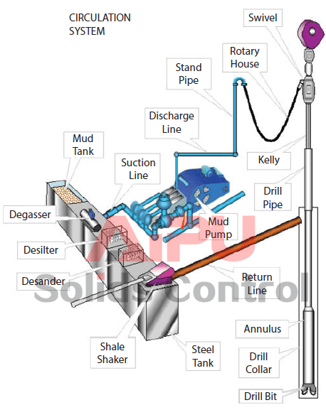
The drilling fluid circulating system is like a close loop electric circuit through which drilling fluid (i.e. mud) can travel from the surface to all the way downhole and back to its initial point (i.e. mud pit).
Drilling fluid (i.e. mud) goes from the mud pits to main rig pumps (i.e. mud pump), and then major components including surface piping, standpipe, kelly hose, swivel, kelly, drill pipe, drill collar, bit nozzles, the various annular geometries (annulus means space between drill pipe and hole) of the open hole and casing strings, flow line, mud control equipment, mud tanks, and again the mud pit/mud pump (Figure 1). It is obvious that the rock cuttings must be removed from the borehole to allow drilling to proceed. This is done by pumping drilling fluid down the drill-string, through the bit and up the annulus.
The cuttings are then separated from the mud, which is then recycled. The circulating system (i.e. drilling fluid) also enables to clean the hole of cuttings made by the bit; to exert a hydrostatic pressure sufficient to prevent formation fluids entering the borehole, and to maintain the stability of the hole by depositing a thin mud-cake on the sides of the hole.
The main components related to the circulating system are mud pumps, mud pits, mud mixing equipment and contaminant removal equipment (Figure 2). The detailed equipment list for this system is shown in Figure 1 and Figure 2. Drilling fluid is usually a mixture of water, clay, weighting material (barite) and chemicals. A variety of mud are now widely used (i.e. oil base, invert oil emulsion).
The mud must be mixed and conditioned in the mud pits, and then circulated by large pumps i.e. sludge pumps (Figure 3). A schematic diagram illustrating a typical rig circulating system along with its flow direction is depicted in Figure 3. The mud is pumped through the whole cycle as mentioned in Figure 3. Once the mud comes back to the surface again, the solids must be removed and the mud is conditioned prior to be re-circulated. These solids and some other contaminants are removed using shale shaker, desander, desilter, and vacuum degasser (Figure 5).
The mud pit is usually a series of large steel tanks, all interconnected and fitted with mud agitators to maintain solids in suspension (Figure 6). Some pits are used for circulating (i.e. suction pit) and others for mixing and storing fresh mud. Most modern rigs have equipment for storing and mixing bulk additives (i.e. barite) as well as chemicals (both granular and liquid). The mixing pumps are generally high volume, low discharge centrifugal pumps (Figure 2). At least two sludge pumps are installed on the rig. At shallow depths, they are usually connected in parallel to deliver high flow rates.
Positive displacement pumps are used (reciprocating pistons) to deliver high volumes at high discharge pressures. The discharge line from the mud pumps is connected to the standpipe, a steel pipe mounted vertically on one leg of the derrick. A flexible rubber hose (i.e. kelly hose) connects the top of the standpipe to the swivel via the gooseneck (Figure 7). Once the mud has been circulated around the system it will contain suspended solids, perhaps some gas and other contaminants. These must be removed before the mud is recycled. The mud passes over a shale shaker, which is basically a shaker screen. This removes the larger particles while allowing the residue (underflow) to pass into settling tanks. The finer material can be removed using desanders, desilter, vacuum degassers, and decanting centrifuges.
If the mud contains gas from the formation it can be passed through a degasser that operates a vacuum, thereby separating the gas from the liquid mud. Having passed through all the mud processing equipment the mud is pumped to settling traps prior to being returned to the mud tanks for recycling. Another tank which is useful for well monitoring is the possum belly tank. This is calibrated to measure the fluid displaced from hole while running in. If the level varies significantly from the expected level a pressure control problem can be identified and necessary actions take place.

A Mud Pump may have many changeable parts, such as liner, piston, extension rod, pulsation dampener, valve, clamp, etc. Lake Petro could provide 100% interchangeable parts of many common brands of pump. We offer Liners with Ceramic (Zirconia and Aluminium oxide) and Steel (Metal and Bi-metal) materials. Piston assembly is the important spare parts and expendable parts of oil drilling mud pumps. Mud pump valve assy include valve body, valve seat, valve insert (valve rubber ). Pulsation Dampener is usually installed on the discharge line to reduce the fluctuation of pressure and displacement of the drilling mud pump. Fluid End Module is an important component of the hydraulic pump end of the mud pump.

The 2,200-hp mud pump for offshore applications is a single-acting reciprocating triplex mud pump designed for high fluid flow rates, even at low operating speeds, and with a long stroke design. These features reduce the number of load reversals in critical components and increase the life of fluid end parts.
The pump’s critical components are strategically placed to make maintenance and inspection far easier and safer. The two-piece, quick-release piston rod lets you remove the piston without disturbing the liner, minimizing downtime when you’re replacing fluid parts.


 8613371530291