
mud pump flow loop schematic in stock

The drilling fluid circulating system is like a close loop electric circuit through which drilling fluid (i.e. mud) can travel from the surface to all the way downhole and back to its initial point (i.e. mud pit).
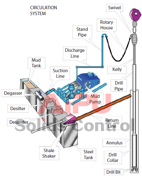
Drilling fluid (i.e. mud) goes from the mud pits to main rig pumps (i.e. mud pump), and then major components including surface piping, standpipe, kelly hose, swivel, kelly, drill pipe, drill collar, bit nozzles, the various annular geometries (annulus means space between drill pipe and hole) of the open hole and casing strings, flow line, mud control equipment, mud tanks, and again the mud pit/mud pump (Figure 1). It is obvious that the rock cuttings must be removed from the borehole to allow drilling to proceed. This is done by pumping drilling fluid down the drill-string, through the bit and up the annulus.
The cuttings are then separated from the mud, which is then recycled. The circulating system (i.e. drilling fluid) also enables to clean the hole of cuttings made by the bit; to exert a hydrostatic pressure sufficient to prevent formation fluids entering the borehole, and to maintain the stability of the hole by depositing a thin mud-cake on the sides of the hole.
The main components related to the circulating system are mud pumps, mud pits, mud mixing equipment and contaminant removal equipment (Figure 2). The detailed equipment list for this system is shown in Figure 1 and Figure 2. Drilling fluid is usually a mixture of water, clay, weighting material (barite) and chemicals. A variety of mud are now widely used (i.e. oil base, invert oil emulsion).
The mud must be mixed and conditioned in the mud pits, and then circulated by large pumps i.e. sludge pumps (Figure 3). A schematic diagram illustrating a typical rig circulating system along with its flow direction is depicted in Figure 3. The mud is pumped through the whole cycle as mentioned in Figure 3. Once the mud comes back to the surface again, the solids must be removed and the mud is conditioned prior to be re-circulated. These solids and some other contaminants are removed using shale shaker, desander, desilter, and vacuum degasser (Figure 5).
The mud pit is usually a series of large steel tanks, all interconnected and fitted with mud agitators to maintain solids in suspension (Figure 6). Some pits are used for circulating (i.e. suction pit) and others for mixing and storing fresh mud. Most modern rigs have equipment for storing and mixing bulk additives (i.e. barite) as well as chemicals (both granular and liquid). The mixing pumps are generally high volume, low discharge centrifugal pumps (Figure 2). At least two sludge pumps are installed on the rig. At shallow depths, they are usually connected in parallel to deliver high flow rates.
Positive displacement pumps are used (reciprocating pistons) to deliver high volumes at high discharge pressures. The discharge line from the mud pumps is connected to the standpipe, a steel pipe mounted vertically on one leg of the derrick. A flexible rubber hose (i.e. kelly hose) connects the top of the standpipe to the swivel via the gooseneck (Figure 7). Once the mud has been circulated around the system it will contain suspended solids, perhaps some gas and other contaminants. These must be removed before the mud is recycled. The mud passes over a shale shaker, which is basically a shaker screen. This removes the larger particles while allowing the residue (underflow) to pass into settling tanks. The finer material can be removed using desanders, desilter, vacuum degassers, and decanting centrifuges.
If the mud contains gas from the formation it can be passed through a degasser that operates a vacuum, thereby separating the gas from the liquid mud. Having passed through all the mud processing equipment the mud is pumped to settling traps prior to being returned to the mud tanks for recycling. Another tank which is useful for well monitoring is the possum belly tank. This is calibrated to measure the fluid displaced from hole while running in. If the level varies significantly from the expected level a pressure control problem can be identified and necessary actions take place.

Closed loop pressurized freshwater liner wash system, complete with integral water cooling tank equipped with centrifugal pump and driven by explosion proof electric motor
Belt drive transmission: two each motor sheaves and QD mounted pump sheaves; banded Kevlar Vbelts; belt guards; for use with AC drive motors c/w 20HP blower assemblies

When two (or more) pumps are arranged in serial their resulting pump performance curve is obtained by adding theirheads at the same flow rate as indicated in the figure below.
Centrifugal pumps in series are used to overcome larger system head loss than one pump can handle alone. for two identical pumps in series the head will be twice the head of a single pump at the same flow rate - as indicated with point 2.
With a constant flowrate the combined head moves from 1 to 2 - BUTin practice the combined head and flow rate moves along the system curve to point 3. point 3 is where the system operates with both pumps running
When two or more pumps are arranged in parallel their resulting performance curve is obtained by adding the pumps flow rates at the same head as indicated in the figure below.
Centrifugal pumps in parallel are used to overcome larger volume flows than one pump can handle alone. for two identical pumps in parallel and the head kept constant - the flow rate doubles compared to a single pump as indicated with point 2
Note! In practice the combined head and volume flow moves along the system curve as indicated from 1 to 3. point 3 is where the system operates with both pumps running
In practice, if one of the pumps in parallel or series stops, the operation point moves along the system resistance curve from point 3 to point 1 - the head and flow rate are decreased.
The 2,200-hp mud pump for offshore applications is a single-acting reciprocating triplex mud pump designed for high fluid flow rates, even at low operating speeds, and with a long stroke design. These features reduce the number of load reversals in critical components and increase the life of fluid end parts.
The pump’s critical components are strategically placed to make maintenance and inspection far easier and safer. The two-piece, quick-release piston rod lets you remove the piston without disturbing the liner, minimizing downtime when you’re replacing fluid parts.

According to this study, increasing the plastic viscosity of the mud results in a remarkable increase in the amount of recovered cuttings. Surprisingly enough, the surplus amount of viscosity inverses the result. These phenomena are clearly seen in Fig. 3a–d.
As far as cuttings transport in highly deviated wells is concerned, researchers offer various ideas about the effect of viscosity on hole cleaning. Some researchers such as Zeidler (1972), Okrajni and Azar (1986), Pilehvari et al. (1999), Jawad (2002), Kelessidis et al. (2007) and Mohammadsalehi and Malekzadeh (2011) believe that raising viscosity of the drilling fluid deteriorates hole cleaning, because type of flow regime changes from turbulent flow to laminar flow; and it has been proved that cuttings can be better displaced in turbulent flow than laminar flow. On the other hand, there are also some investigators, for instance, Ford et al. (1990), Iyoho and Takahashi (1993), Belavadi and Chukwu (1994), Shou (1999), Li et al. (2004) who claim that improvement in hole cleaning occurs as viscosity increases.
Figure 3a–d are for 1.74 mm cuttings size and each figure is a representative of one specific angle (i.e., 60°, 70°, 80°, or 90°). In all figures, cuttings transport performance (CTP) has been plotted versus viscosity. A line in each individual graph depicts a constant flow rate for the three distinctive types of drilling fluid with three different viscosities (1, 2.5, and 6 cp).
Cuttings transport performance versus viscosity for four distinct hole inclinations from vertical, i.e. a θ = 60°, b 70°, c 80° and d 90°, with different flow velocities , i.e. 1.84, 2.21, 2.58, 3.31 ft/s
It is visible from Fig. 3a–d that primary increasing viscosity from 1 to 2.5 cp results in better CTP for all four different flow rates regardless of hole inclination. The effect of viscosity was, nevertheless, negative when the viscosity of the mud was intensified to 6 cp.
The best explanation for such a behavior of mud can be extracted from rheological laws defined for distinguishing various types of flow, namely laminar flow, transient flow, and turbulent flow. The type of flow of a fluid is characterized by the Reynolds number Re.
It is true to say that by increasing viscosity of the fluid at the same flow rate, the current flow regime tends to convert to laminar flow from turbulent flow. However, it should be noticed that converting a turbulent flow to laminar flow requires passing through a wide range of Reynolds number including transition zone. Thus, the author prepared a general graph which indicates how viscosity affects CTP by changing flow regime (Fig. 4).
It can be interpreted from Fig. 4 graph that CTP is improved by increasing viscosity while other factors such as velocity and hole inclination are kept constant. This happens until the flow is still turbulent, but once reaching the transition zone CTP gradually decreases till the end of this region. Subsequently, laminar flow becomes transition flow by further increase of viscosity at the same condition. Among those three types of flow regimes, turbulent flow is the most desirable one followed by transition and laminar flows. The effect is prevailing at lower and higher velocities and for all hole inclinations. All these phenomena can be explained by the definition of each flow regime. As the flow is laminar, any laminar layer of the fluid is displaced, with respect to other laminar layers, in parallel to the direction of flow, and is moving at its individual speed. For flow through a cylindrical tube, the flow rate is highest along the axis of the tube. At the tube wall it is zero throughout the volume of the fluid. However, turbulent flow consists of small eddies throughout the volume of the fluid, and this character of this type of flow produces more momentum force which gives better movement of cuttings of course.
The resistance of drilling fluid to flow is defined by the term called plastic viscosity which indicates the extent of physical and chemical interactions between fluids and solid particles applied into the mud. In general, any increment of solid content in drilling mud, such as barite and fluid loss materials, will result in higher plastic viscosity. The presence of shale particles in drilling fluid system when drilling through a shale zone will also increase the plastic viscosity. Strictly speaking, the higher plastic viscosity generates higher resistance in mud which in turns will affect cutting lifting performance. The situation may be worsened by the increase of ultra-fine drill solids in the drilling fluid which causes incremental trend of plastic viscosity at constant mud weight. This phenomenon explains how geology variations impacts on the cutting transport. Therefore, the size of drill cuttings as well as formation shale content should be put into consideration before designing the drilling fluid. In this research work, clean sand particles of 1.70 mm were used as the drill cuttings. Therefore, their effect on mud viscosity was negligible.
Lines in these curves indicate types of chosen mud in every run of the experiment. Rhombic markers belong to the mud with viscosity of 1 cp, square markers have a viscosity of 2.5 cp and triangle markers have the highest viscosity by the value of 6 cp. The existing distance between lines also shows different types of mud with different rheological properties. Four angles had been selected for this study namely 60°, 70°, 80°, and 90° from vertical. All lines give an upward trend by diverging from vertical, indicating that CTP has improved. Some researchers such as Okrajni and Azar (1986), Ford et al. (1990), and Bilgesu and Chukwu (2007), believed that if hole angle increases, their negative influences on cutting transports will increase as well. However, the author believes that it also has some positive effects especially when the flow is laminar. It is obvious that at higher degrees of inclination the tendency of downward cuttings bed sliding is more likely to occur which increases the hydraulic requirement for adequate hole cleaning. These beds moved at a lower speed along the annular space so that at the end of the test period, there may be some beds about to approach the outlet of the annulus section and if the test period has lasted for a few extra minutes there is a great chance for the nearby moving beds to leave the annular section. Thus, it is believed that a slight increase in hole inclination causes these large moving bed to reach the outlet before the end of the test period; thus a considerable increase in WRP and CTP.
Most portions of the injected cuttings were recovered by highest velocity of the drilling fluid and the most viscous mud. This fact also supports previous discussion about viscosity of mud in which increasing the viscosity can improve CTP if the flow regimes is still turbulent.
All in all, these results coincide well with vast majority of previous experimental work. Many researchers have already reported the effect of flow rate on hole cleaning, such that as the flow rate is increased, a reduction on cuttings bed area will be experienced.

This application claims priority to and benefit of U.S. Patent Application No. 62/403,488, entitled “SYSTEM FOR USING PRESSURE EXCHANGER IN MUD PUMPING APPLICATION”, filed Oct. 3, 2016, which is herein incorporated by reference in its entirety.
The subject matter disclosed herein relates to fluid handling, and, more particularly, to systems and methods for pressurizing and pumping drilling fluids (“drilling mud”) to a drilling rig to be sent down a drill string.
Drilling mud is used in oil and gas drilling applications to provide hydraulic power, cooling, well control (e.g., using the weight and pressure of the mud to control the well, which may encounter pressurized fluids in the formation), to cool the drilling head and to carry cuttings away from the cutting head. In drilling applications, drilling mud is typically pressurized (e.g., 5,000 to 7,500 PSI or more) and pumped using a mud pump to a drilling rig and down the drilling pipe to a cutting head via a drill string. The used drilling mud and the cuttings then flow back up through an annulus between the drilling pipe and a casing. However, in some embodiments, the drilling mud flow down through the annulus between the drilling pipe and the casing and then up the drilling pipe to the rig.
Drilling mud may include cuttings, clay, various minerals, aggressive chemicals, salts, and miscellaneous other components that may place stress on the mud pump, and in some cases shorten the lifespan of the mud pump. Accordingly, when selecting a mud pump, durability may be a driving factor.
FIG. 8 is a schematic of an embodiment of the drilling application in which particulates from the separator are added to the mud loop, and water removed by the centrifuge is added to the water loop;
In many drilling applications drilling mud is pressurized and pumped down the drill string to the cutting head to provide hydraulic power, cooling, well control (e.g., using the weight and pressure of the mud to control the well, which may encounter pressurized fluids in the formation), and displacement of the cuttings. The used drilling mud travels back up to the surface through an annulus between the drill string and a casing. The used drilling mud may then be cleaned and reused. Drilling mud may include cuttings, clay, various minerals, aggressive chemicals, salts, and miscellaneous other components that may place stress on the mud pump, which may shorten the lifespan of the mud pump.
As discussed in detail below, by pressurizing a clean fluid (e.g., water) with a pump and then using a hydraulic energy transfer system, such as a pressure exchanger (PX), to transfer work and/or pressure from the high pressure clean fluid to the drilling mud allows the drilling mud to be pumped and pressurized without running the drilling mud through the pump. In some embodiments, the hydraulic energy transfer system may be a rotating isobaric pressure exchanger that transfers pressure between a high pressure fluid (e.g., high pressure energizing clean fluid, such as pressurized water) and a low pressure fluid (e.g., drilling mud). The utilization of the PX eliminates the need to run the drilling mud through a mud pump, which may stress or damage the pump more than water. The PX is compact, durable, easy to maintain, and can easily be deployed with redundancy.
The PX may include one or more chambers (e.g., 1 to 100) to facilitate pressure transfer and equalization of pressures between volumes of first and second fluids. In some embodiments, the pressures of the volumes of first and second fluids may not completely equalize. Thus, in certain embodiments, the PX may operate isobarically, or the PX may operate substantially isobarically (e.g., wherein the pressures equalize within approximately +/−1, 2, 3, 4, 5, 6, 7, 8, 9, or 10 percent of each other). In certain embodiments, a first pressure of a first fluid (e.g., a high pressure energized clean fluid) may be greater than a second pressure of a second fluid (e.g., drilling mud). For example, the first pressure may be between approximately 5,000 kPa to 25,000 kPa, 20,000 kPa to 50,000 kPa, 40,000 kPa to 75,000 kPa, 75,000 kPa to 100,000 kPa or greater than the second pressure. Thus, the PX may be used to transfer pressure from a first fluid (e.g., high pressure energized clean fluid) at a higher pressure to a second fluid (e.g., drilling mud) at a lower pressure.
FIG. 1 is a schematic view of an embodiment of a drilling application 2. As illustrated, a drill string 4 extends through a casing 6 below a surface 8 of the earth, where a cutting head 10 drills into the earth. Drilling fluids (“drilling mud”) are typically pressurized (e.g., 5,000 to 7,500 psi or more) and pumped down the drill string 4 to the cutting head 10 to provide hydraulic power, cooling, well control (e.g., using the weight and pressure of the mud to control the well, which may encounter pressurized fluids in the formation), and displacement of the cuttings. The drilling mud is then pumped up, away from the cutting head 10, and through the annulus between the drill string 4 and the casing 6. The used mud carries the cuttings away from the cutting head 10. In typical riser drilling applications, the used mud is pumped up through the annulus between the drill string and the casing back up to the surface 8. The used drilling mud may go through one or more cleaning systems 12 or processes (e.g., shale shaker, degasser, desander, desilter, centrifuge, etc.) and then be deposited in a mud pit 14.
Typically, drilling mud from the mud pit 14 is pressurized and pumped using a mud pump. However, clay, salt, and minerals in the drilling mud may put stress on a mud pump that may shorten its lifespan. In the illustrated embodiment, a PX 16 is used to pressurize and pump the drilling mud. Specifically, clean fluid (e.g., water) from a clean fluid supply 18 (e.g., a water tank) is pressurized (e.g., 5,000 to 7,500 psi or more) using a pump 20 and supplied to the high pressure (HP) inlet 22. The pump may be a triplex plunger pump with a discharge pulsation damper, or some other pump suitable for pumping clean fluids. Drilling mud from the mud pit 14 is supplied to the low pressure (LP) inlet. The PX 16 transfers pressure from the high pressure clean fluid to the low pressure drilling mud, outputting low pressure clean fluid through the LP outlet 26, and high pressure drilling mud through the HP outlet 28. Though FIG. 1 shows a single PX 16, it should be understood that a drilling application 2 may include multiple PXs 16, coupled to one another by plumbing or manifolds, which may have valves for switching PXs 16 online and offline. The clean fluid from the LP outlet 26 is deposited in the water tank 18. The drilling mud from the HP outlet 28 travels to and down the drill string 4.
Thus, the drilling application may include a drilling mud loop 30 and a clean fluid loop 32, which may only interact with one another, if at all, in the PX 16. The PX 16 has fewer moving parts and is generally better suited to processing drilling mud than the pump 20. Thus, because the pump 20 is pumping clean fluid (e.g., water) rather than drilling mud, the pump 20 undergoes less stress than a comparable pump in an embodiment in which the pump pumps drilling mud. In some embodiments, the pump 20 handling clean fluid rather than drilling mud may alter the pump 20 used in the system 2. For example, because the pump 20 processes water, rather than drilling mud, a pump that is less durable, but offers better performance or efficiency may be selected instead. Similarly, in some applications, the mud cleaning system 12 may be less thorough because the mud no longer needs to be clean enough to be processed by the pump 20.
FIG. 2 is an exploded view of an embodiment of a rotary PX 16 that may be utilized in place of a mud pump in a drilling application, as described in detail below. As used herein, the PX 16 may be generally defined as a device that transfers fluid pressure between a high-pressure inlet stream and a low-pressure inlet stream at efficiencies in excess of approximately 50%, 60%, 70%, or 80% without utilizing centrifugal technology. In this context, high pressure refers to pressures greater than the low pressure. The low-pressure inlet stream of the PX 16 may be pressurized and exit the PX 16 at high pressure (e.g., at a pressure greater than that of the low-pressure inlet stream), and the high-pressure inlet stream may be depressurized and exit the PX 16 at low pressure (e.g., at a pressure less than that of the high-pressure inlet stream). Additionally, the PX 16 may operate with the high-pressure fluid directly applying a force to pressurize the low-pressure fluid, with or without a fluid separator between the fluids. Examples of fluid separators that may be used with the PX 16 include, but are not limited to, pistons, bladders, diaphragms and the like. In certain embodiments, isobaric pressure exchangers may be rotary devices. Rotary isobaric pressure exchangers (PXs) 16, such as those manufactured by Energy Recovery, Inc. of San Leandro, Calif., may not have any separate valves, since the effective valving action is accomplished internal to the device via the relative motion of a rotor with respect to end covers, as described in detail below with respect to FIGS. 2-7. Rotary PXs 16 may be designed to operate with internal pistons to isolate fluids and transfer pressure with little mixing of the inlet fluid streams. Reciprocating PXs 16 may include a piston moving back and forth in a cylinder for transferring pressure between the fluid streams. Any PX 16 or plurality of PXs 16 may be used in the disclosed embodiments, such as, but not limited to, rotary PXs, reciprocating PXs, or any combination thereof. While the discussion with respect to certain embodiments for measuring the speed of the rotor may refer to rotary PXs 16, it is understood that any PX 16 or plurality of PXs 16 may be substituted for the rotary PX 16 in any of the disclosed embodiments.
In the illustrated embodiment of FIG. 2, the PX 16 may include a generally cylindrical body portion 40 that includes a housing 42 and a rotor 44. The rotary PX 16 may also include two end structures 46 and 48 that include manifolds 50 and 52, respectively. Manifold 50 includes inlet and outlet ports 54 and 56 and manifold 52 includes inlet and outlet ports 60 and 58. For example, inlet port 54 may receive a high-pressure first fluid and the outlet port 56 may be used to route a low-pressure first fluid away from the PX 16. Similarly, inlet port 60 may receive a low-pressure second fluid and the outlet port 58 may be used to route a high-pressure second fluid away from the PX 16. The end structures 46 and 48 include generally flat end plates 62 and 64, respectively, disposed within the manifolds 50 and 52, respectively, and adapted for liquid sealing contact with the rotor 44. The rotor 44 may be cylindrical and disposed in the housing 42, and is arranged for rotation about a longitudinal axis 66 of the rotor 44. The rotor 44 may have a plurality of channels 68 extending substantially longitudinally through the rotor 44 with openings 70 and 72 at each end arranged symmetrically about the longitudinal axis 66. The openings 70 and 72 of the rotor 44 are arranged for hydraulic communication with the end plates 62 and 64, and inlet and outlet apertures 74 and 76, and 78 and 80, in such a manner that during rotation they alternately hydraulically expose liquid at high pressure and liquid at low pressure to the respective manifolds 50 and 52. The inlet and outlet ports 54, 56, 58, and 60, of the manifolds 50 and 52 form at least one pair of ports for high-pressure liquid in one end element 46 or 48, and at least one pair of ports for low-pressure liquid in the opposite end element, 48 or 46. The end plates 62 and 64, and inlet and outlet apertures 74 and 76, and 78 and 80 are designed with perpendicular flow cross sections in the form of arcs or segments of a circle.
With respect to the PX 16, an operator has control over the extent of mixing between the first and second fluids, which may be used to improve the operability of the PX 16. For example, varying the proportions of the first and second fluids entering the PX 16 allows the operator to control the amount of fluid mixing within the PX 16. Three characteristics of the PX 16 that affect mixing are: the aspect ratio of the rotor channels 68, the short duration of exposure between the first and second fluids, and the creation of a liquid barrier (e.g., an interface) between the first and second fluids within the rotor channels 68. First, the rotor channels 68 are generally long and narrow, which stabilizes the flow within the PX 16. In addition, the first and second fluids may move through the channels 68 in a plug flow regime with very little axial mixing. Second, in certain embodiments, at a rotor speed of approximately 1200 RPM, the time of contact between the first and second fluids may be less than approximately 0.15 seconds, 0.10 seconds, or 0.05 seconds, which again limits mixing of the streams. Third, a small portion of the rotor channel 68 is used for the exchange of pressure between the first and second fluids. Therefore, a volume of fluid remains in the channel 68 as a barrier between the first and second fluids. All these mechanisms may limit mixing within the PX 16.
FIG. 7 is a more detailed schematic of an embodiment of the drilling application 2 shown in FIG. 1. As previously discussed, used drilling mud exits the annulus between the drill string 4 and the casing 6 and enters the mud cleaning system 12. As shown, the mud cleaning system 12 may include a shale shaker 150 to separate cuttings from the used drilling mud. The cuttings may be deposited in a cuttings pit 152. As illustrated, the used drilling mud is then processed by a degasser 154, a desander 156, a desilter 158, and a centrifuge 160 and/or mud cleaner. It should be understood however, that the mud cleaning system 12 may include any combination of the previously mentioned components, in any order, or combinations with additional components. Further, the mud cleaning system 12 may include one or more intermediate mud pits 162 or tanks to store drilling mud between processes. The drilling mud may exit the mud cleaning system 12 and be deposited in the mud pit 14. In some embodiments, the mud loop 30 includes a mixer and a hopper 164 to keep the drilling mud in the mud pit 14 moving and mixed up, to add mud to the mud pit 14, to change the composition of the mud, or to increase flow rates. Though the mixer and hopper 164 in FIG. 7 is shown outside the dotted line that encompasses the mud cleaning system 12, in some embodiments, the mixer and hopper 164 may be considered a part of the mud cleaning system 12. A charge pump 166 (e.g., a centrifugal pump) may be used to supply drilling mud from the mud pit 14 to the LP inlet 24 of the PX 16.
Meanwhile, a charge pump 168 draws clean water from the water tank 18 and supplies clean water to the high pressure pump 20. The high pressure pump 20 pressurizes the clean water to 5,000-7,500 psi or more and pumps the water to the HP inlet 22 of the PX 16. As previously discussed, the PX 16 transfers pressure from the high pressure clean fluid to the low pressure drilling mud. High pressure drilling mud exits the PX 16 via the HP outlet 28 and is pumped down the drill string 4. Low pressure clean fluid exits the PX 16 via the LP outlet 26. Low pressure clean water exiting the PX 16 may go through a separator 170 to remove particulates from the clean water. As discussed in more detail below, in some embodiments (e.g., embodiments with lead flow), the clean water and the drilling mud may interact with one another within the PX 16. In such situations, the high pressure drilling mud may exit the PX 16 via the HP outlet 28 carrying some of the clean water. Similarly, the clean water may exit the PX 16 via the LP outlet 26 carrying particulate picked up from the drilling mud within the PX 16. Accordingly, the separator 170 may be used to remove the particulate from the clean water. In some embodiments, the separator 170 may use flocculants or other clumping agents to separate particulates from the water. As will be discussed in more detail later, the particulates removed from the clean water may be discarded or returned to the mud loop 30. In other embodiments, the clean water loop 32 may include other components for cleaning or treating the clean water.
In some embodiments, the flow of clean water between the PX 16 and the water tank may be controlled by controlling the operation of the PX 16 (e.g., via the charge pump 166). In other embodiments, the water loop may include a valve 172 (e.g., a flow control valve) for controlling the flow of clean water between the PX 16 and the water tank 18. As discussed above, in embodiments of the drilling application 2 with lead flow, clean water may be mixed with the drilling mud in the PX 16 and exit the HP outlet 28 with the drilling mud. Accordingly, in such an embodiment, some clean water may transition from the clean water loop 32 to the mud loop 30. In such an embodiment, a water makeup flow 174 may add water to the water tank 18 in order to maintain a relatively constant amount of water in the clean water loop 32. In some embodiments, the water makeup flow may also help provide a cooling effect by cooling the clean water loop.
In some embodiments, the drilling application 2 may include a controller 180 for controlling operation of the mud loop 30 and the clean water loop 32. The controller 180 may control the PX 16, the high pressure pump 20, the charge pumps 166, 168, the valve 172, the motor 176, the VFD 178, any combination thereof, or other components within the system. For example, the controller may control flow rates (e.g., via valve position), pump speed, motor speed, VFD signals, etc. The controller 180 may include a memory component 182 for storing data and/or programs and a processor 184 for running programs stored on the memory 182. The processor 184 may include one or more general-purpose processors, one or more application specific integrated circuits, one or more field programmable gate arrays, or the like. The memory 182 may be any tangible, non-transitory, computer readable medium that is capable of storing instructions executable by the processor 184 and/or data that may be processed by the processor 184. The memory 182 may include volatile memory, such as random access memory, or non-volatile memory, such as hard disk drives, read-only memory, optical disks, flash memory, and the like.
The controller 180 may act based on inputs received from one or more sensors 186 disposed throughout the system and configured to sense flow rates, valve positions, pump speeds, densities, fluid levels, etc.
Though not shown, in some embodiments, the drilling application 2 may include various heat transfer or cooling components (e.g., heat exchangers, heat sinks, heating components, cooling components, etc.) to heat or cool mud in the mud loop 30 or water in the clean water loop 32.
FIG. 8 is a schematic of an embodiment of the drilling application in which particulates separated from the clean water by the separator 170 are added to the mud loop 30 via the mud mixer or hopper 164 and water removed from the drilling mud by the centrifuge 160 is sent to the water tank 18. As described above, in some embodiments, the clean water and drilling mud may interact with one another in the PX 16. In such cases, the drilling mud may pick up some of the clean water and/or the clean water may pick up some particulates from the drilling mud. In such a case, the separator may be used to separate particulates from the clean water after the water exits the PX. In some embodiments the particulates may be discarded. In other embodiments, the particulates may be added to the drilling mud in the mud pit 14 and travel with the drilling mud through the mud loop 30.
Similarly, the centrifuge 160 of the mud cleaning system 12 may be used to separate (e.g., extract) water from the drilling mud. As shown, the extracted water may be added to the water tank 18. In other embodiments, the extracted water may be discarded.
FIG. 9 is a schematic illustrating flow rates in an embodiment of the drilling application 2 with balanced flow. The flow of the drilling application 2 is balanced when the high pressure flow rate (i.e., the flow rate into the HP inlet 22 and out of the HP outlet 28) is substantially the same as the low pressure flow rate (i.e., the flow rate into the LP inlet 24 and out of the LP outlet 26). For example, the high pressure flow rate may be within 1%, 2%, 3%, 4%, 5%, 6%, 7%, 8%, 9%, 10%, 11%, 12%, 13%, 14%, 15%, or some other value, or the low pressure flow rate. As shown, the flow rates Q in each portion of the mud loop 30 and the clean water loop 32 are expressed as a percentage of the flow rate of drilling mud out of the HP outlet 28 of the PX 16 and to the drill string 4. As shown, the flow rate Q of the used drilling mud out of the casing 6 is 100, plus cuttings and minus any fluid losses. As the drilling mud goes through the mud cleaning system 12, the flow rate Q decreases. For example, drilling mud may exit the mud cleaning system 12 with a flow rate Q of 80, 85, 90, 95, or some other value. The mud mixer and hopper 164 may be used to increase the flow rate Q by 5%, 10%, 15%, 20%, or some other value such that drilling mud enters the PX 16 at the LP inlet 24 at a flow rate Q of 100.
Similarly, water may be pumped from the water tank and into the HP inlet 22 of the PX 16 at a flow rate Q of 105, assuming approximately 5% leakage or lubrication flow (e.g., fluid which migrates from the HP flow to the LP flow within the PX 16). Water exits the PX 16 at a flow rate Q of 105, goes through the separator, and is deposited in the water tank 18. In the balanced flow embodiment illustrated in FIG. 9, the flow rate Q of the water makeup flow 174 may be small, or in some cases, even zero. For example, the flow rate Q of the water makeup flow 174 may be 0, 1, 2, 3, 4, 5, 6, 7, 8, 9, 10, or some other value. In some embodiments, the water makeup flow 174 may be used to account for water lost to leakage.
FIG. 10 is a schematic illustrating flow rates in an embodiment of the drilling application 2 with 20% lead flow (e.g., the HP flow rate is greater than the LP flow rate). As shown, the flow rate of the used drilling mud out of the casing 6 is 100, plus cuttings and minus any fluid losses. As the drilling mud goes through the mud cleaning system 12, the flow rate Q decreases. For example, drilling mud may exit the mud cleaning system 12 with a flow rate Q of 80, 85, 90, 95, or some other value. In the lead flow example, the mud mixer and hopper 164 are not used to increase the flow rate Q, such that drilling mud enters the PX 16 at the LP inlet 24 at a flow rate Q of less than 100. For example, drilling mud may enter the LP inlet 24 of the PX 16 at a flow rate Q of 70, 75, 80, 85, 90, or some other value. As the drilling mud travels through the PX, the drilling mud may take on some of the clean water such that the drilling mud exits the HP outlet 28 of the PX 16 at a flow rate Q of 100.
Similarly, water may be pumped from the water tank and into the HP inlet 22 of the PX 16 at a flow rate Q of 105, assuming approximately 5% leakage. Because the drilling mud takes on some of the clean water as it travels through the PX 16, water exits the LP outlet 26 of the PX 16 at a lower flow rate Q (e.g., 70, 75, 80, 85, 90, or some other value), goes through the separator, and is deposited in the water tank 18. Water may be added to the water tank 18 via the water makeup flow 174 to account for water taken on by the drilling mud in the PX 16. For example, the flow rate Q of the water makeup flow 174 may be 10, 15, 20, 25, 30, or some other value. The water makeup flow 174 may also be used to account for water that leaks to the drilling mud in the PX 16. In some embodiments, the water makeup flow 174 may also be used to cool the clean water loop.
FIG. 11 is a flow chart of a process for pressurizing drilling mud. In block 202, used drilling mud is received from the well (e.g., from the annulus between the drill string and the casing). In block 204, the used drilling mud may be cleaned. As described above, this may include shale shaking to separate the drilling mud from the cuttings, degassing, desanding, desilting, and running through a centrifuge to separate various components of the drilling mud. Once cleaned, the drilling mud may be deposited in a mud pit. In block 206, low pressure drilling mud is provided to the LP inlet of the PX. In block 208, the clean fluid (e.g., clean water) is pressurized using a pump and provided to the HP inlet of the PX. In block 210, the pressures are exchanged between the high pressure clean fluid and the low pressure drilling mud. Thus, the low pressure drilling mud is pressurized and the high pressure clean fluid is depressurized. The high pressure drilling mud exits the PX via the HP outlet. The low pressure clean fluid exits the PX via the low pressure outlet. In block 212, the low pressure clean fluid is deposited in the water tank or other containment device. In some embodiments (e.g., lead flow) a water make up flow may supply supplemental water to the water tank in order to make up for water lost to leakage or taken on by the drilling mud in the PX. In block 214 the pressurized drilling mud is provided to the cutting head via the drill string. The drilling mud provides hydraulic power, cooling, well control (e.g., using the weight and pressure of the mud to control the well, which may encounter pressurized fluids in the formation), and also carries cuttings away from the cutting head as the drilling mud is pumped back up to the surface in the annulus between the casing and the drill string.
Using one or more PXs to transfer pressure from a clean fluid to drilling mud for mud pumping in a drilling application means that the high pressure pump pumps clean fluid, rather than drilling mud. Thus, the high pressure pump does not have to withstand the stress caused by cuttings, clay, various minerals, aggressive chemicals, salts, and miscellaneous other components in the drilling mud. The disclosed techniques may result in increased lifespan and increased efficiency of the high pressure pump relative to typical systems in which the high pressure pump pumps drilling mud. Additionally, in some configurations, because the pump is pumping clean fluid instead of drilling mud, a higher performance or more efficient pump may be chosen because durability is not as much of a concern. Similarly, because the pump is not pumping drilling mud, in some instances the mud cleaning process may be less thorough, thus potentially saving time and money.

Technical Field Thi8 inVentiGn iS related to da~a tran~mission systems for borehole telemetry or measurem~nt while drilling systems. More specifically the i~vention is related to a measu,rement while drilling system wherein data is transmitted from the downhole instrument through pressure pulsations of the drilling fluid within the drill string to the earth"s surface. ~le invention is directed to an apparatus or il-tering data passed through pressure pulsations in the drilling Eluid rom downhole equipment to the earthls surface in order to remove the influence of data disturbing pulsations occurring because of the drillirlg Eluid circulating pump.
-2-systems include transmission of the data hy electromagne-tic methods, insulated conductor or hardwire systems, acoustical methods and pressur~ pulse modulation of the drilling fluid or mud. Each of these systems has its advantages and disadvantages and the particular system with which this patent appli.cation is concerned utilizes ~he mud pressure pulse concept.
In a measurement while drilling system utilizing mud pressure pu].sation as a technique to transfer data, it is subject to interference caused by other pressure pulsations in the drilling fluid flow pathO rhe primary source of these interferring pressure pulsations is the circulating pump(s) ~or the drilling fluid or mud. This circulating pump contains a plurality of pistons, valves and other mechanical hardware that not only move the drilling fluid through the drill string but create pressure pulsations which represent noise or interference w.ith respect to the pressure pulsations produced by the transmitter of the measurement while driLling equipment.
Because the measurement while drilling system uses the drilling fluid as a pathway for transmission of data noise or pressure interference is undesirable. The noise or interference in pressure pulses p.roduced by the drilling fluid circulating pump can be of such a magnitude that it will substantially mask or obscure the data from the measurement while dr.illi.ng equipment unless .it .is properly removed by the data receiving 0quipment at the earth"s surface. In study.ing this noise or interference it has been noted that the character of the interference produced by a particular drilling fluid circulating pump is not uniEorm and w.ill vary between types o~ p~nps, manufactures of purnps, and even between identical pumps at a particular drilling rig installation. Also, the characteristic pressure pwlsations for a specific pump will change in rela-tion to the operating speed of the pump. In view of -this it is observed that if a noise or interference filter iB to ~e effective in filtering or rernoving this pulse presswre interference it must be able to accor~modate the changing conditions between installations and parti~ular equipment -to be feasible for commercial operation and to be practical to accommodate changing conditions as they miyht occur on a particular drilling rig. Accordingly, it is a purpose of this invention to solve the a~ove described problem and provide a filtering s~stem to remove -this objectionable noise or interference from the drilling fluid or mud flow stream.
According to one aspect of the invention resi~es in a borehole measurement while drilling system for passing data in the form of a modula-ted data signal s-tream through drilling fluid in a drill string wherein a circui-t means is provided for substantially removing interferring pressure pulsations caused by a drilling rig"s drilling fluid circulating pump from the data stream. The system includes means for generating a first signal responsive to the repetitive strokes or a drilling fluid circulating pump and means for generating a second signal responsive to fluid pressure in a drilling fluid medium that is carrying a pulsed data stream and has pressure pulses from a drillin~
fluid circulating pump. Means is provided for generating a third signal responsive to fluid velocity in the drilling fluid medium that is carrying a pulsed data stream~ and a signal combiner means is coupled to receive the secon~
signal and third signal and operably continuously subtract the third signal from the second signal thereby providing an enhanced second signal as a resultant signal. An adapti~e estimator means is adapted to receive the first signal and the second signal and retain as a stored signal a long term average representa-tion of the second signal in A sequence coordinated with the first signal and stro3ces of the pump. A subtraction means is coupled to the adaptive estimator means and the means for generating a second signal and is operable to receive the second sign~l for subtracting the stored signal from the second signal in a sequence related to the strokes of the pump such that a resultant signal is produced that is representative o~ the data signal of the borehole measurement while drilling system that was introduced into the drilling fluid.
Another aspect of the invention resides in a borehole measurement while drilling ~ystem for a drilling rig with a drill fluid circulating pump wherein a sensor is provided in a drill string adapted to sense a geophysical parameter in a borehole and produce a data signal representative of the sensed physical parameter. A
The receiver has a filter means therein adapted to remove from the transmitted data signal the pressure pulse influence of the drilliny fluid circulating pump such that the transmitted data signal may be recovered without such inter-ference. The filter means includes a timing circuit means ~or sensing strokes of the pump and producing a timing signal representative thereo~. A signal combiner means is coupled to the pressure transducer and the velocity transducer and is operable to combine the signals fxom the transducers into an enhanced pressure data representative signal with an adaptive estimator means receiving the timing signal and the enhanced pressure data signal from -the slgnal combiner means and operable to temporarily store same data signal in correlatiorl with the timing signal and to produce an output signal in correlation with the timin~ signal that is representati~e of an extended term relation to the enhanced pressure data signal~ A subtraction means is operable to xeceive the enhanced pressure data signal and selectively remove therefrom the adaptive estimat~r output signal in correlation with the tirning signal in order to reproduce the composite data signal representative of the data signal of the sensor. The comparator means receives the - 3a -sb/Jc composite data sicJnal and has means -to compare that da-ta signal wi-th a predetermined value and determine if the composite data signal is within predetermined ~alue limits and produce therefrom an output data signal repr~sentative of the data signal of the sensor and related to the sensed geophysical parameter.
It can be seen, therefore, that the present invention provides a pump noise filtering apparatus ~or a borehole measurement while drilling system which includes an adaptive estimator having a memory that utilizes samples of pressure and velocity measurements taken from the drilling fluid flow stream in a sequence related to cyclic operation of the mud pump~ Signals relatecl to these pressure measurements are stored and then removed ~rom the continuing pressure signal measurements in a sequence correlated to the pumps cyclic operation in order to remove thîs noise or interference from the sensed data prior to passing it into a receiver, processor and display portion of the ~easurement while drilling system. The stored signal data is rereshed with each p~p cycle in order to adjust the data for changing pump noise conditions.
This invention is capable of providing a pump noise cancelling or filterin~ apparatus for a measurement while drilling system that has an adaptive estimator -that will selectively reco~nize the character and magnitude of the pressure pulse influences from a drill~g Eluid circulating pump or mud pump of a drilling r.ig and includin~
other circuitry that will selec-tively remove this influence from the pressure modulated data from the ~easurement while drilling system that is extracted ~rom the drilling fluid flow stream in the transmission of this data to the earth~s surface.
It can be further seen that this invention provides a pump noise cancelling apparatus that will adapt to chanc~ing pump noise or interference conditions in order to - 3b -sb/).~
Description of the Drawings Fig. 1 is a schematic and pictorial representation of a measurement while drilling apparatus using a mud pressure modulation transmission -~echnique and installed in an earth borehole;
Fig. 4 is a detailed schematic of an adaptive estimator circuit that can be used in this inven-tion; and Fig. 5 is a ~chematic diagram of the noise filtering apparatus circuit for use in the present invention where a plurali-ty of mud pumps are present.
The following is a discussion and description of preferred speciEic embodiments of the pump noise iltering apparatus of this invention, ~uch being made with reeerence to the drawings, whereupon the same reference numerals are used to indicate the ~ame or similar parts and/or ~tructure. It is to be understood that ~uch discussion and description is not to unduly limit the scope oE the invention.
Transmitter 20 in this type of measurement while drilling system is a device kno~l in the axt -to encode data from sensor 18 into pressure pulsations in the drilling Eluid or mud that is contained within drill string 10. These pressure pulsations travPl through the drilling fluid or mud upward from their point of origin at transmitter 20 to the surface equipment where the pressure pulsations are sensed by a pressure sensor 22 and the drilling fluid velocity is sensed by velocity sensor 23. Pressure sensor 22 and velocity sensor 23 are both communicably connected wi-th the interior of a conduit 24 through which the drilling fluid or mud passes. This conduit 24 is in a portion of the drilling flow loop between the drilling fluid mud pump 26 and a swivel connection 27 a-t the upper end of drill string 10.
Pressure sensor 22 and velocity sensor 23 are electrically connected with a receiver 28 that i5 used to extract the intelligence carrying data from the measurements -ta]cen ~rom the mud in drilling fluid Elow line conduit 24. The pump noise iltering or cancelling apparatus o~ this inven-tion would normally be contained within receiver 28 of this measurement while drilling system. From receiver 28 the data is transmitted to a data processor and display apparatus 30 that is operable or mathematically manipulating, further processing, and displaying the data in a desired and usable form such as a visual representa-tion, a magnetic tape or a printed document.
Drilling fluid circulating pump 26 is the primary source of the noise or interference that is sought to be ramoved by the apparatus of this invention. For the typical oilfield operation this pump is a reciprocating piston type pump in either a duplex (two piston~ or triplex (three piston) construction. A great many of these pumps are single acting pumps however some of them may be double acting pumps. In either case they have the 1uid flow into and out o~ them controlled by check valves. The normal operation of these pumps will provide a substantially high pressure source of dri~ling fluid at a significant flow rate for the normal drilling operation as is well known in the industry. Because of the reciprocating nature of these pumps and their use of check valves, they produce pressure pulsations in the drilling fluid flow stream. The nature and characteristics of these pulsations effects both the mud"s pressure and velocity and the e~tent of the effect depends upon the particular physical construction of the speciic pumpO It has been observed that these pulsations or fluctuations in the drilling fluid are cyclical in relation to the strokes of the pump and that this produces a cyclic or periodic pressure pulsation pattern in the drilling flllid as detected by pressure sensor 22 in drilling 1uid 10w line conduit 24. These pulsations also 2S effsct the drilling fluid velocity and this influence is detected by velocity sensor 23. Drilling fluicl pump 26 is itted with a pump stroke sensor to permit the monitoring of the pump"s strokes at a preselected point within its pumping c~cle. This pwmp stroke sensor includes a pickup device 29 that is mechanically mounted at the pump and adapted to sense the p~lp"s position at a regular occurring interval of the pump stroke cycle in order to provide data for correlating the pressure pulse cycle o~ -the drilling fluid.
Fig. 2 show9 a schematic representation oE the pump noise filtering or cancelling apparatus circuitry o this invention in a block diagram form. The wave forms shown at various portions of Fig. 2 indicate the shape of the various signals at the several portions of the apparatus. Pump ~6 has its pump stroke sensor connected to a timing circuit 320 The ou~put signal from the pump stroke sensor i5 a plurality of pulses spaced apart in a sequence corresponding with strokes of the pump so that timing circuit 32 can use this pump stroXe signal to generate a signal that is responsive to the repetitive stro~es of drilling fluid circulating pump 26. The output from timing circuit 32 is chosen to be a square wave as illustrated.
Pressure sensor 22 and velocity sensor 23 both provide a con~inuous sensing of the respective pressure and velocity pulsations in drilling fluid flow line conduit 24. When the measurement while drilling system is operating the output signal from pressure sensor 22 and velocity sensor 23 are i5 representative OL the combined pressure pulsat:ions of the measurement while ~rilling transmitter and the pressure pulsations emanating from drilling flui~ circulating p~p 26 because both of these are present in the drilling fluid flow line conduit 24. The wave forms of both of these signals contain some peaks that are significantly higher than others. The larger peaks are representative of positive pressure pulses from pump 26. Other peaks in this ~ave form can possibly be suspected as coming from the measurement while drilling transmitter. However specific correlation and identification of this data by only a visual examination is efective and inaccurate. The signal from pressure sensor 22 has the ~ignal rom velocity sensor 23 directed into a combiner circuit 25. Combiner circuit 25 functions to combine both o~ its input signals into a single output ~ignal. More specifically combiner circuit 25 operably subtracts the data si~nal velocity sensor 23 from the data signal of pressure sensor 23. Because the measured wave forms of these two measured parameters are similar t~e data signal resultant from the subtraction is a refin~d or ~5 improved representation of the pressure measurement data with certain velocity related disturbances or noise removed therefrom. In general this combining or subtraction process improves the signal to noise ratio vf the pressure data signal. Because the output rom combiner circuit 25 is an ~ .
Adaptive estimator circuit .i5 connected to receive -the output from timing circuit 32, to receive the enchanced pressure sensor signal from combiner circuit 25, and provide an output that is fed in~o subtraction circuit 36. Adaptive e~timator circuit 34 is provided with circuitry to memorize or store data that is representative of specific portions of the pressure sensor output signal from combiner circuit 25 in correspondence with strokes of the pump and in correlation with the output signal from timing circuit 32, The input to adaptive estimator 34 is divided into a plurality pressure data sample segmen-ts between like portions of each pump stroke interval. During each pressure data sample segment the enhanced pressure sensor data is sampled by and stored in adaptive estimator circuit 34.
Thus for each stroke of the pump (one pump stroke interval) a plurality of samples of -the enhanced pressure sensor data are taken (one in each pressure sample segment). As these samples of the pressure data are accumulated the stored or representative value in adaptive estimator circui-t can be changed with each repetitive stroke oE the pump. r~is is done in order to permit the data stored in the adaptive estimator circuit to closely follow the pumps operation and t~us accommodate changing operatin~ conditions. This adaptive estimator circuit 34 performs the function of a tracking commutative ~ilter which is to estimate the approximate value of the following data sample in each pressure sample segment by retaining the sum of previous such weighted values and modifying or adjusting that ~alue to correspond with a new data sample during that particular pressure sample segment o~ each pump stroke interval.
This adaptive estimator circuit 34 includes a memory that functions to retain a representative of the data from the pressure sensor. This memory must be capable of adapting or varying its retained data to accommodate changing data that is resultant ~rom the operating conditions at a well. In general the adaptive estimator circuit 34 functions as a specific adaptation of a filter generally Xnown as a tracking commutative filter. An example of such a changing condi~ion is a simple change in the pump"s opera~ing speed that would affect -the pulse rate from the pump stroke sensorO An additional change that might influence the pump"s pressure pulse characteristics would be raising the drill string from the drilling position so that drill bit 12 instead of being a-t the bottom o the borehole is in an elevated position a short distance above the borehole bottom. This is a condition that might be used or temporary circulation of the drilling fluid.
Returning to the description of Figs. 1 and 2 subtraction circuit 36 is provided with an input Erom combiner circuit 25 and an input from adaptive estimator circuit 34. Subtraction circuit 36 functions to remove from the pressure sensor signal those por-tions which are indicative Oe the pressure pulsations -that are sequenced with and related to drilling fluid circulating pump 26.
This removal of the selec~ed portions of ~he data signal from the pressure sensor data is done in correlation with the pump strokes as by -timing circuit 32. Removal of these portions of the pressure sensor signal is done by subtracting from the pressure sensor data a valu2 representa-tive of those portions of the pressure sensor ~10--data which occur in a repetitive, correlatable sequence with the pump"s strokes~ m e resultan-t signal from this subtraction or removal process carries the intelligence data from the transmit-ter of the measurement while drilling apparatus with the dlstorting influence of drilling fluid circulating pump 26 having been substantially removedO A
Fig. 3 shows in block diagram schematic form an embodiment of the adaptive estimator circuit and the subtraction circuit portions of this inven-tion. Pump stroke sensor 40 associated with drilling fluid circulating pump 26 provides a pulsed output signal as shown. This output signal is fed into a flip flop circuit 42 -that shapes the signal in-to a rectangular wave form as illustrated. Phase lock loop circuit 44 receives the output from flip flop circuit 42 and functions to synchronize its outpu-t timing pulses with the timing pulse signal from pump stroke sensor 7~
40 so -that each timing pulse from flip flop circuit 42 occupies a fixed and constant time in-~erval with respect to the pump stroke cycle. The output from phase lock loop circuit 44 is ~onnected -to an input of adap~ive estimator circuit 34.
It is to be noted that this wave form is only generally representative of the wave form that can occur at this location. The specific shape of the t~pical or representative wave form will vary depending upon the speed of operation of the drilling fluid circulating pump and also upon the static pressure and the velocity of fluid in the drilling fluid conduit 24. Because this wave form i5 subject to some changes in shape it will influence the wave form output from adder circuit 50. q~he illustrated wave -forms shown in Figs. 2 and 3 are to be considered as approximate or representative or illustrative of the actual wave forms that may be present in actual practice o:~ this invention.
Adaptive estimator 34 is described above and funct.~ons -to prewhiten or process before manipulation the data signal received from buffer 46 duri.ng the pressure sample time segments designated by the timing c:ircuit. It receives 6ignals :Erom phase lock loop 44 and from buf:Eer 46 and provides a data signal to the input of an inverter 48.
The output of bufer 46 is divided with one portion going to the input of inverter 48 and the other portion going to the input of the adaptive memory or tracking commutative filter, The adaptive memory or tracking commutative filter has a plurality of capacitors 52 connected in parallel between a buss line 55 carrying the output from buffer 46 and a multiplexing circuit 54. Multiplexing circui-~ 54 basically functions as a plurality of switches that function to connect the plurality of capacitors 52 one at a time between ground and buss line 55 in sequence with timing signals rom phase lock loop circuit 44. Multiplexirly circuit 54 can be a convent:ional integrated circui-t having a plurality of multiplexing parts corresponding with the num~er of pressure sample segments that are selected for divisiorls of t.he pump stroke interval. The clock or timing sequence input to multip:Lexer 54 is through a plurality o~
connections rom phase lock loop ciruit 44, For each purnp stroke interval the plurality of capacitors are each sequentially connected during their associated portion of the pump stroke interval or during their designated pressure sample segment of that interval. The capacitors are each charged to a value approximating the value of the data signal during the interval in which they are individually connected. Charging the capacitors in this manner provides a long term average of the data signal value during the pressure sample segment time interval as is well known in commutative filters.
In the situations where a plurality of drilling 1uid circulating pumps are used in a drilling rig ~aving a measurement while drilling apparatus it is necessary to provide a plurality of cascaded pump noise filtering devices in order to selectively remove the noise or pressure and velocity pulsa-tion influence of these specific pumps.
Fig~ 5 illustrates in schematic block diagram form such a pump noise filtering apparatus which is representative of that which could be utilized to filter the pump noise or


 8613371530291