
mud pump flow loop schematic for sale

During drilling in Oil and Gas exploration, drilling mud or Bentonite is pumped into boreholes for multiple reasons. Pumping drill mud into boreholes cools the drill bit as well as bringing drill cuttings to the surface as the way in which mud is pumped into boreholes forms a closed loop system. The use of drilling mud also provides hydrostatic pressure to prevent liquids such as oil and gas rising to the surface, as drilling mud is thixotropic meaning when it is not agitated it stiffens forming a mud which is an effective liquid and gas barrier.
Closed loop pressurized freshwater liner wash system, complete with integral water cooling tank equipped with centrifugal pump and driven by explosion proof electric motor
Belt drive transmission: two each motor sheaves and QD mounted pump sheaves; banded Kevlar Vbelts; belt guards; for use with AC drive motors c/w 20HP blower assemblies

We stock fluid end parts for the5×6 mud pump, 5×6-1/4 FM45 mud pump, 5×8 mud pump, 5-1/2×8 mud pump, 5X10 mud pump, 4-1/2×5 mud pump, 7-1/2×8 mud pump, and 7-1/2X10 mud pump. The Gardner Denver mud pump model numbers for the above pumps are as follows: 5X6-FGFXG, 5X8-FDFXX, 5-1/2X8-FDFXX, 5X10-FDFXD, 4-1/2X5-FFFXF, 7-1/2X8-FYFXX, 7-1/2X10-FYFXD. We also handle Wheatley, Gaso, Worthington, Failing and Centerline parts and pumps. We also stock Foot Valve, Liner Puller, Valve Seat Puller, (4″ Inline Check Valve. Our Gardner Denver mud pump parts are not only competitively priced, they are also made in the USA. Oil Recommended by Gardner Denver. Call any of our experienced representatives to get the help and knowledge you deserve.

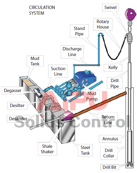
The drilling fluid circulating system is like a close loop electric circuit through which drilling fluid (i.e. mud) can travel from the surface to all the way downhole and back to its initial point (i.e. mud pit).
Drilling fluid (i.e. mud) goes from the mud pits to main rig pumps (i.e. mud pump), and then major components including surface piping, standpipe, kelly hose, swivel, kelly, drill pipe, drill collar, bit nozzles, the various annular geometries (annulus means space between drill pipe and hole) of the open hole and casing strings, flow line, mud control equipment, mud tanks, and again the mud pit/mud pump (Figure 1). It is obvious that the rock cuttings must be removed from the borehole to allow drilling to proceed. This is done by pumping drilling fluid down the drill-string, through the bit and up the annulus.
The cuttings are then separated from the mud, which is then recycled. The circulating system (i.e. drilling fluid) also enables to clean the hole of cuttings made by the bit; to exert a hydrostatic pressure sufficient to prevent formation fluids entering the borehole, and to maintain the stability of the hole by depositing a thin mud-cake on the sides of the hole.
The main components related to the circulating system are mud pumps, mud pits, mud mixing equipment and contaminant removal equipment (Figure 2). The detailed equipment list for this system is shown in Figure 1 and Figure 2. Drilling fluid is usually a mixture of water, clay, weighting material (barite) and chemicals. A variety of mud are now widely used (i.e. oil base, invert oil emulsion).
The mud must be mixed and conditioned in the mud pits, and then circulated by large pumps i.e. sludge pumps (Figure 3). A schematic diagram illustrating a typical rig circulating system along with its flow direction is depicted in Figure 3. The mud is pumped through the whole cycle as mentioned in Figure 3. Once the mud comes back to the surface again, the solids must be removed and the mud is conditioned prior to be re-circulated. These solids and some other contaminants are removed using shale shaker, desander, desilter, and vacuum degasser (Figure 5).
The mud pit is usually a series of large steel tanks, all interconnected and fitted with mud agitators to maintain solids in suspension (Figure 6). Some pits are used for circulating (i.e. suction pit) and others for mixing and storing fresh mud. Most modern rigs have equipment for storing and mixing bulk additives (i.e. barite) as well as chemicals (both granular and liquid). The mixing pumps are generally high volume, low discharge centrifugal pumps (Figure 2). At least two sludge pumps are installed on the rig. At shallow depths, they are usually connected in parallel to deliver high flow rates.
Positive displacement pumps are used (reciprocating pistons) to deliver high volumes at high discharge pressures. The discharge line from the mud pumps is connected to the standpipe, a steel pipe mounted vertically on one leg of the derrick. A flexible rubber hose (i.e. kelly hose) connects the top of the standpipe to the swivel via the gooseneck (Figure 7). Once the mud has been circulated around the system it will contain suspended solids, perhaps some gas and other contaminants. These must be removed before the mud is recycled. The mud passes over a shale shaker, which is basically a shaker screen. This removes the larger particles while allowing the residue (underflow) to pass into settling tanks. The finer material can be removed using desanders, desilter, vacuum degassers, and decanting centrifuges.
If the mud contains gas from the formation it can be passed through a degasser that operates a vacuum, thereby separating the gas from the liquid mud. Having passed through all the mud processing equipment the mud is pumped to settling traps prior to being returned to the mud tanks for recycling. Another tank which is useful for well monitoring is the possum belly tank. This is calibrated to measure the fluid displaced from hole while running in. If the level varies significantly from the expected level a pressure control problem can be identified and necessary actions take place.

Needle valves are used to throttle or shut-off flow of fluids. They usually will vary flow with pressure or viscosity change. Some valves can be pressure and/or temperature compensating.
Flow control valves are used to control oil flow in one direction and unrestricted in the opposite direction. "Metered in" control means that the flow controls are controlling the fluid into the actuator, "metered out" is controlling the fluid out of the actuator. Some valves can be pressure and/or temperature compensating.
When the pilot line to a pilot-operated check valve is not pressurized, flow is allowed in one direction but blocked in the opposite direction. When the pilot line in a pilot-to-open valve is pressurized, the check valve is open, allowing flow in either direction.
When the pilot line to a pilot-operated check valve is not pressurized, flow is allowed in one direction but blocked in the opposite direction. When the pilot line in a pilot-to-close valve is pressurized, the check valve is closed, blocking flow in both directions.
Flow fuses are normally open valves which close if the pressure difference between the inlet and outlet valves is too high compared to the design setting. The valve can be reset by reversing the direction of flow. When placed inline with an actuator (for example, a cylinder), flow fuses limit the maximum speed of that actuator.
Directional control valves are used to direct fluid flow into the appropriate lines for the designated operation. These valves are usually electrically controlled.
Hydraulic pumps are used to pump oil from the power unit to other parts of the hydraulic system. Some pumps have control options such as pressure or flow compensators.
Proportional valves are electrically controlled hydraulic valves. These valves proportionally control the hydraulic pressure and/or flow based on an electrical input signal.

A Mud Pump may have many changeable parts, such as liner, piston, extension rod, pulsation dampener, valve, clamp, etc. Lake Petro could provide 100% interchangeable parts of many common brands of pump. We offer Liners with Ceramic (Zirconia and Aluminium oxide) and Steel (Metal and Bi-metal) materials. Piston assembly is the important spare parts and expendable parts of oil drilling mud pumps. Mud pump valve assy include valve body, valve seat, valve insert (valve rubber ). Pulsation Dampener is usually installed on the discharge line to reduce the fluctuation of pressure and displacement of the drilling mud pump. Fluid End Module is an important component of the hydraulic pump end of the mud pump.

My first days as an MWD field tech I heard horror stories surrounding what is commonly referred to as “pump noise”. I quickly identified the importance of learning to properly identify this “noise”. From the way it was explained to me, this skill might prevent the company you work from losing a job with an exploration company, satisfy your supervisor or even allow you to become regarded as hero within your organization if you’ve proven yourself handy at this skill.
“Pump noise” is a reference to an instability in surface pressure created by the mud pumps on a modern drilling rig, often conflated with any pressure fluctuation at a similar frequency to pulses generated by a mud pulser, but caused by a source external to the mud pulser. This change in pressure is what stands in the way of the decoder properly understanding what the MWD tool is trying to communicate. For the better part of the first year of learning my role I wrongly assumed that all “noise” would be something audible to the human ear, but this is rarely the case.
A mud pulser is a valve that briefly inhibits flow of drilling fluid traveling through the drill string, creating a sharp rise and fall of pressure seen on surface, also known as a “pulse”.
Depending on if the drilling fluid is being circulated in closed or open loop, it will be drawn from a tank or a plastic lined reservoir by a series(or one) mud pumps and channeled into the stand pipe, which runs up the derrick to the Kelly-hose, through the saver sub and down the drill-pipe(drill-string). Through the filter screen past an agitator or exciter, around the MWD tool, through a mud motor and out of the nozzles in the bit. At this point the fluid begins it’s journey back to the drilling rig through the annulus, past the BOP then out of the flow line and either over the shale shakers and/or back in the fluid reservoir.
Developing a firm grasp on these fundamentals were instrumental in my success as a field technician and an effective troubleshooter. As you can tell, there are a lot of components involved in this conduit which a mud pulser telemeters through. The way in which many of these components interact with the drilling fluid can suddenly change in ways that slightly create sharp changes in pressure, often referred to as “noise”. This “noise” creates difficulty for the decoder by suddenly reducing or increasing pressure in a manner that the decoder interprets a pulse. To isolate these issues, you must first acknowledge potential of their existence. I will give few examples of some of these instances below:
Suction screens on intake hoses will occasionally be too large, fail or become unfastened thus allowing large debris in the mud system. Depending on the size of debris and a little bit of luck it can end up in an area that will inhibit flow, circumstantially resulting in a sudden fluctuation of pressure.
Any solid form of drilling fluid additive, if improperly or inconsistently mixed, can restrict the flow path of the fluid resulting in pressure increase. Most notably this can happen at the pulser valve itself, but it is not the only possible outcome. Several other parts of this system can be affected as well. LCM or loss of circulation material is by far the most common additive, but the least overlooked. It’s important for an MWD technician to be aware of what’s being added into the drilling fluid regardless if LCM isn’t present. Through the years I have seen serval other improperly mixed additives cause a litany of pressure related issues.
This specifically is a term used to refer to the mud motor stator rubber deterioration, tearing into small pieces and passing through the nozzles of the bit. Brief spikes in pressure as chunks of rubber pass through one or more nozzles of the bit can often be wrongly interpreted as pulses.
Sometimes when mud is displaced or a pump suction isn’t completely submerged, tiny air bubbles are introduced into the drilling fluid. Being that air compresses and fluid does not, pulses can be significantly diminished and sometimes non-existent.
As many of you know the downhole mud motor is what enables most drilling rigs to steer a well to a targeted location. The motor generates bit RPM by converting fluid velocity to rotor/bit RPM, otherwise known as hydraulic horsepower. Anything downhole that interacts with the bit will inevitably affect surface pressure. One of the most common is bit weight. As bit weight is increased, so does surface pressure. It’s important to note that consistent weight tends to be helpful to the decoder by increasing the amplitude of pulses, but inconsistent bit weight, depending on frequency of change, can negatively affect decoding. Bit bounce, bit bite and inconsistent weight transfer can all cause pressure oscillation resulting in poor decoding. Improper bit speed or bit type relative to a given formation are other examples of possible culprits as well.
Over time mud pump components wear to the point failure. Pump pistons(swabs), liners, valves and valve seats are all necessary components for generating stable pressure. These are the moving parts on the fluid side of the pump and the most frequent point of failure. Another possible culprit but less common is an inadequately charged pulsation dampener. Deteriorating rubber hoses anywhere in the fluid path, from the mud pump to the saver sub, such as a kelly-hose, can cause an occasional pressure oscillation.
If I could change one thing about today’s directional drilling industry, it would be eliminating the term “pump noise”. The misleading term alone has caused confusion for countless people working on a drilling rig. On the other hand, I’m happy to have learned these lessons the hard way because they seem engrained into my memory. As technology improves, so does the opportunities for MWD technology companies to provide useful solutions. Solutions to aid MWD service providers to properly isolate or overcome the challenges that lead to decoding issues. As an industry we have come a lot further from when I had started, but there is much left to be desired. I’m happy I can use my experiences by contributing to an organization capable of acknowledging and overcoming these obstacles through the development of new technology.

This Unit incorporates a Nitrogen Pumping System capable of pumping high pressure gas at rates of up to 180,000 SCFH/85m3/min and at pressures of up to 10,000 PSI/69 mPa. This Nitrogen Pumping System connects to a single 3,000 gallon (11.36 M3) liquid nitrogen tank that will be installed at the rear of the Trailer.
The nitrogen side of the Unit is powered by a CAT C15 Diesel Engine rated at a maximum of 540 @ 2100 RPM. The Unit is equipped with a cryogenic centrifugal boost pump, cryogenic high pressure Triplex Pump, non-fired vaporizer system and other components.
All of the hydraulically driven components are powered from the Unit mounted Diesel Engine. During normal operation, liquid nitrogen flows from the cryogenic liquid nitrogen storage tank through the centrifugal boost pump (where suction pressure is boosted) to the Triplex Pump, where it is pressurized by reciprocating pistons to downstream pressure.
The high pressure liquid then flows through the non-fired nitrogen vaporizer system absorbing a sufficient amount of heat to raise the gaseous nitrogen discharge temperature to 15 to 21 Deg C (60 to 70 Deg F) and flows out to a discharge valve as high pressure gas at rates of up to 180,000 SCFH/85m3/min and at pressures of up to 10,000 PSI/69 mPa. This Unit may be controlled locally from the Control Console installed in a Unit mounted Control Cabin.

GD Energy Products HD and STD drilling modules are compact and built to last, delivering high performance, pressure and flow rates more than two times longer than others. Made with individually forged, heat-treated alloy steel using our proprietary Autofrettage technique, each module offers extended life and maximum strength, yet can be welded to repair washouts. And service is simple with built-in patent pending Falcon Technology, with a single-piece, twist-in retainer, and no fasteners required.


 8613371530291