mud pump flow rate calculator quotation

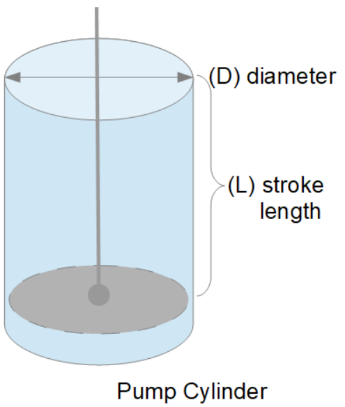
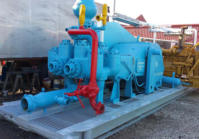
Rig pump output, normally in volume per stroke, of mud pumps on the rig is one of important figures that we really need to know because we will use pump out put figures to calculate many parameters such as bottom up strokes, wash out depth, tracking drilling fluid, etc. In this post, you will learn how to calculate pump out put for triplex pump and duplex pump in bothOilfield and Metric Unit.

When it comes to pumping terminology, one crucial term to know is GPM — a measurement that will help you determine if you’re choosing the right pump. So what is GPM, and how do you calculate it?
GPM stands for gallons per minute and is a measurement of how many gallons a pump can move per minute. It is also referred to as flow rate. GPM is variable based on another measurement known as the Head, which refers to the height the water must reach to get pumped through the system. It is also referred to as flow rate. GPM is variable based on another measurement known as the Head, which refers to the height the water must reach to get pumped through the system.
Pumps are typically measured by their GPM at a certain Head measurement. For example, a pump specification may read 150 GPM at 50 Feet of Head, which means the pump will work at 150 gallons per minute when pumping water at a height of 50 feet.
The GPM formula is 60 divided by the number of seconds it takes to fill a one gallon container. So if you took 10 seconds to fill a gallon container, your GPM measurement would be 6 GPM (60/10 seconds = 6 GPM). To most accurately calculate GPM, you use the pressure tank method and formula. For this calculation, you need to know the specifications of your pressure tank, including how many gallons it holds, the gallon drawdown and the PSI. The manufacturer specifies the gallon drawdown. Once you have that information, as well as a stopwatch to keep time, follow these steps:
For example, if it took four minutes for the pressure switch to turn off, and your gallon drawdown was 20 gallons, this would mean a GPM rate of five.
GPM identifies the unique capabilities of a pump so you can select the right one for your specific needs. If you need a pump for a larger public area such as a golf course, marina or lake, you will need a pump with a much higher GPM than one used for your home’s well. Plus, choosing the correct pump is essential for reducing your costs and increasing your pump’s lifespan.
At GeoForm International, we are a leading manufacturer of high-quality submersible pumps, dredges, digester packages and aerators, all of which are made in the U.S. With our pump expertise, we know just how essential GPM is in the pumping and dredging industry from how much equipment costs to how long jobs will take.

We provide hydraulic components & repair services for industrial applications like paper mills, saw mills, steel mills, recycling plants, oil & gas applications and mobile applications, including construction, utility, mining, agricultural and marine equipment. This includes hydraulic pumps, motors, valves, servo/prop valves, PTOs, cylinders & parts.

Crown"s CPS101-3 Three Pump Stroke Counter Rate Meter displays the total strokes and strokes per minute for three pumps, giving the operator the ability to monitor the flow rate of three mud or water pumps at once. Built with the toughest material on the market, Crown CPS101-3 three pump stroke counter/rate meter will stand up to anything that the oilfield can throw at it. The Three Pump Stroke Counter System is ready to use out of the box with everything you"ll need to measure the flow rate of three mud pumps. In this system, you will get the following:
Crown CPS101-3 three pump rate meter is built in a rugged, all stainless steel case, with easy-to-read LCD screens that are powered by a long-life lithium battery. The system is a self-powered, low-voltage, and self-contained, making it intrinsically safe. Being water-proof, vibration resistant, and extreme weather resistant, the CPS101-3 three pump stroke counter system will provide up to 5 years of use, under normal operating conditions. The front panel control is easy-to-use with power and reset buttons to reset each pump and will monitor three pumps all at the same time. Each pump has a LCD screen that monitors total accumulated strokes up to 9,999 and strokes per minute from 8 to 240 strokes.
Need more information about our three pump stroke counter systems? Check out our Stroke Counter Page or our Blog. And if you only need one of the components of this system, give us a call, We"re more than happy to get you exactly what you need.

When two (or more) pumps are arranged in serial their resulting pump performance curve is obtained by adding theirheads at the same flow rate as indicated in the figure below.
Centrifugal pumps in series are used to overcome larger system head loss than one pump can handle alone. for two identical pumps in series the head will be twice the head of a single pump at the same flow rate - as indicated with point 2.
With a constant flowrate the combined head moves from 1 to 2 - BUTin practice the combined head and flow rate moves along the system curve to point 3. point 3 is where the system operates with both pumps running
When two or more pumps are arranged in parallel their resulting performance curve is obtained by adding the pumps flow rates at the same head as indicated in the figure below.
Centrifugal pumps in parallel are used to overcome larger volume flows than one pump can handle alone. for two identical pumps in parallel and the head kept constant - the flow rate doubles compared to a single pump as indicated with point 2
Note! In practice the combined head and volume flow moves along the system curve as indicated from 1 to 3. point 3 is where the system operates with both pumps running
In practice, if one of the pumps in parallel or series stops, the operation point moves along the system resistance curve from point 3 to point 1 - the head and flow rate are decreased.

Mud pump liner selection in today"s drilling operations seldom (at best) considers electrical implications. Perhaps, with more available useful information about the relationships between mud pump liner size and operational effects on the electrical system, certain potential problems can be avoided. The intent of this paper is to develop those relationships and show how they affect an electrical system on example SCR rigs.Introduction
There, seems to be little consideration for the relationships between liner size and demand on a rig"s engine/generator set(s). Yet, consideration for this relationship can prove to be very helpful to drillers and operators in efficiency of a rig"s electrical system. In order to develop the relationships and help drillers and operators understand the importance of each, relationships between liner size, pump speed, pump pressure, and electrical power will be developed. Only basic physical laws will be used to develop the relationships; and, once developed, the relationships are readily applied to realistic examples utilizing a mud pump manufacturer"s pump data. Finally, conclusions will be drawn from the examples.DEVELOPMENT OF RELATIONSHIPS BASIC RELATIONSHIPS
where HHP= Hydraulic horsepower, GPM = Mud pump volumetric flow rate in gallons per minute, and PST Mud pump output pressure in pounds peer square inch.
Hydraulic horsepower is reflected to the mud pump motor via a multiplier for mechanical efficiency. it follows that motor horsepower is then represented by

The policy set forth below outlines the personal data that Power Zone Equipment may collect, how Power Zone Equipment uses and safeguards that data, and with whom we may share it. This policy is intended to provide notice to individuals regarding personal data in an effort to be compliant with the data privacy laws and regulations of the jurisdictions in which Power Zone Equipment operates.
Power Zone Equipment will use personal data only in ways that are compatible with the purposes for which it was collected or subsequently authorized by you. While Power Zone Equipment will take reasonable steps to ensure that personal data is relevant to its intended use, accurate, complete, and current, Power Zone Equipment is also relying upon each individual to assist in providing accurate updates of his or her personal data.
Power Zone Equipment website(s) may contain “links” to websites owned and operated by third parties. By accessing these links, which are provided for your convenience, you will leave our site and will be subject to the privacy practices of the other website. This policy does not apply to any personal information you provide to unrelated third parties.
Upon request, Power Zone Equipment will grant individuals reasonable access to personal data that it holds about them. In addition, Power Zone Equipment will take reasonable steps to permit individuals to correct, amend, or delete information that is demonstrated to be inaccurate or incomplete. Power Zone Equipment also relies upon each individual to assist in providing accurate updates of his or her personal data. In order to access, correct, amend, or delete the personal data Power Zone Equipment holds about an individual, the individual should contact the following:
To the extent required by applicable law, Power Zone Equipment will grant individuals reasonable access to personal data that Power Zone Equipment holds about them and will take reasonable steps to permit such individuals to correct, amend, or delete information that Power Zone Equipment holds about them. Power Zone Equipment also relies upon each individual to assist in providing accurate updates of his or her personal data. In order to access, correct, amend, or delete the personal data Power Zone Equipment holds about an individual, the individual should contact his or her Power Zone Equipment commercial contact or contact us at the following email address:sales@powerzone.com.
Power Zone Equipment reserves the right to modify this policy from time to time in order that it accurately reflects the legal and regulatory environment and our data collection principles. When material changes are made to this policy, Power Zone Equipment will post the revised policy on our website.

High-pressure mud pumps are positive displacement pumps. Simply, they convert mechanical power into hydraulic power. Their mechanical components (power ends) ar

Pump curves are calculated based on water which has an SG of 1. If a fluid has a higher specific gravity than water, then the head will show the same, but the pressure will increase since Pressure is a function relative to fluid calculated by multiplying Head x Specific Gravity.
The pressure supplied by a pump for each application is fluid dependent and relative to fluid density thus pressure will change according to the fluid’s specific gravity
Care must be taken where a pump curve shows a high NPSH is required. A fluid with a low specific gravity, must be checked against the NPSH required carefully.
Cavitation can occur if the inlet pressure is below that required by the pump, which can arise when the SG of the fluid is not accounted for correctly, when determining the NPSH available.
Positive Displacement Pump CurveA PD Pump curve will not be affected in the same way as a centrifugal pump curve by the specific gravity of a fluid, as flow rate will remain constant. However, the absorbed power will increase, with the pressure produced remaining fluid dependent.

In the process of using the pump, it is often necessary to calculate the pump flow, but many people do not know the pump flow calculation formula. We will take the submersible pump and gear pump as an example to introduce the pump flow calculation formula in detail.
102 is a unit finishing constant. Pump effective power / pump shaft power = pump efficiency (generally 50% - 90%, large pump is higher) The energy obtained by the pump per unit weight of liquid is called the lift. The lift of the pump, including the suction stroke, is approximately the difference between the pump outlet and the inlet pressure. The lift is indicated by H and the unit is meters (m).
The efficiency of the pump refers to the ratio of the effective power of the pump to the shaft power. The power of the η=Pe/P pump usually refers to the input power, that is, the power that the prime mover transmits to the pump shaft, so it is also called the shaft power, which is denoted by P. The effective power is the product of the pump head and mass flow and gravity acceleration.
Submersible pump flow calculation formula: 60HZ flow × 0.83 = 50HZ flow 60HZ lift × 0.69 = 50HZ lift 60HZ power ÷ 1.728 = 50HZ motor power motor output power = Q (flow) × H (head) / 367.2 / efficiency × 1.15 motor output power = shaft power × 1.15 pump efficiency = Q × H × 0.00272 / motor power Q represents flow; H represents the head; 0.83 / 0.69 / 1.728 / 367.2 / 1.15 / 0.00272 are all coefficients.
The gear oil pump flow calculation formula is: Z——number of teeth; n——number of revolutions, revolutions/minutes; ηv——volume efficiency, for general gear oil pumps, the value can be taken as 0.70~0.90; q——the volume of the pit between the two teeth, cubic meters.


 8613371530291