
mud pump frame cover in stock
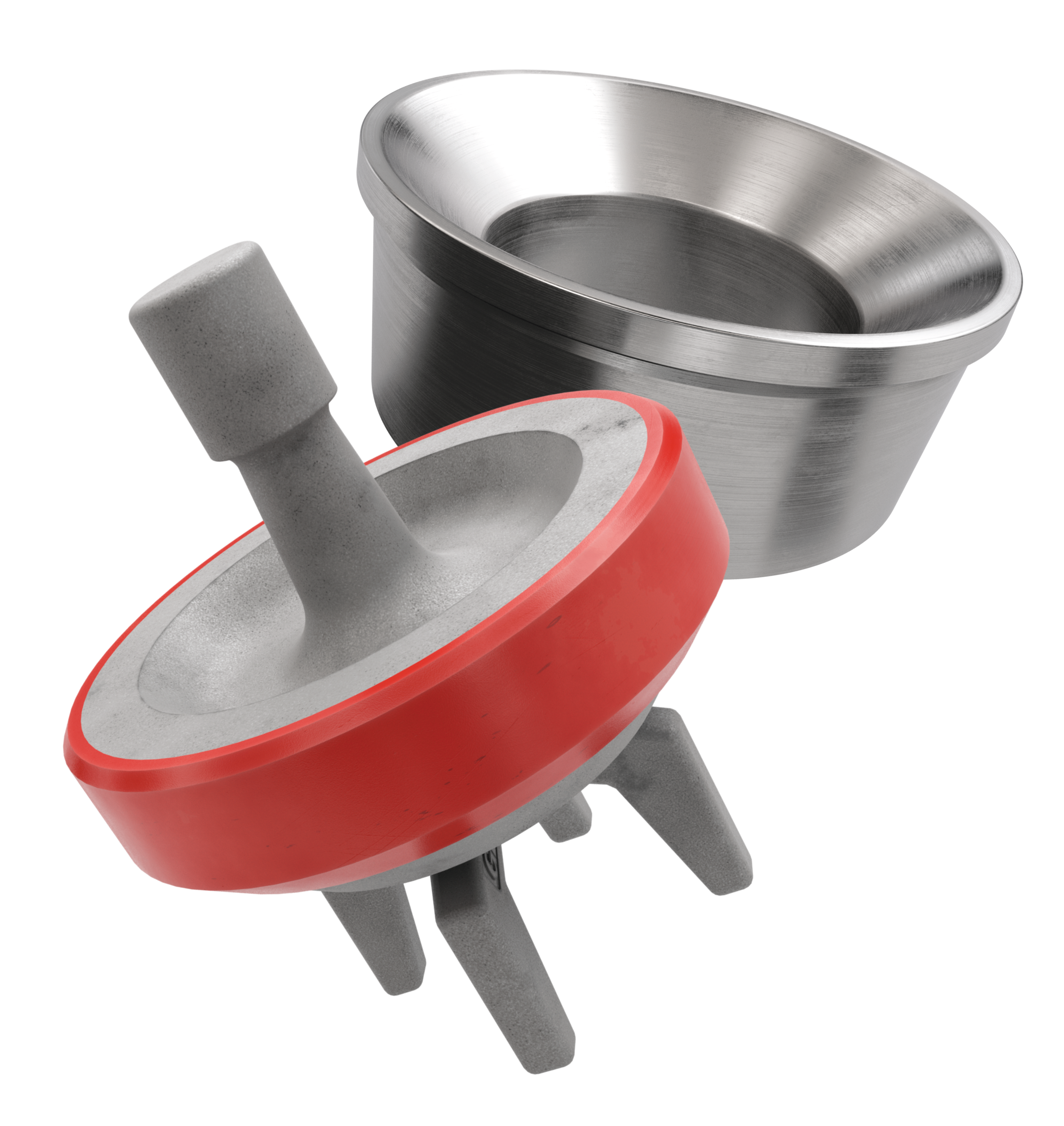
Our full-open valves and seats are designed for use in GD Energy Products PZ, F-Series, and National 12P lines of triplex drilling pumps. This gives you options to use these parts across your whole fleet of pumps.
Includes shaft, sleeve (if required), coupling key, retaining ring, bearings, bearing lock nut, lock washer, bearing housing O-ring, bearing housing, labyrinth oil seals, bearing frame, and viewpoint.

This is a standard 4″ Mud Pump wet end (for threaded-shaft engines), designed to handle solids contaminated water (max 25mm solids) and applications where high-volume trash water capacity is needed. This trash pump body is purpose built for heavy duty industrial applications. For a pump that truly exceeds your expectations, you can’t choose better pump bodies and pair it with heavy duty ZS Engine. This trash pump body kit contains complete pump unit and additional fitting kit including seals, filter cover, pipe joints & hose clips. This trash pump is an ideal addition to any construction sites, mining sites, storm drains where water is mixed with debris.
The products shown below are direct replacements to the drain cover shown above.They are designed to fit in/over the existing mud frame. Please ensure that the replacement drain cover has an adequate volumetric flow rating to meet the application"s highest flow potential and that the application meets the replacement drain cover"s sump depth requirements. For more information about this, please
Drain covers must be sized to handle the highest possible flow rate for the specific pump and system - not the flow rate the pump is expected to operate at most of the time. A pump’s highest potential flow rate is found at the end of the model’s specific performance curve, it’s important to select a cover with a higher flow rating.
NOTICE:Pump flow potential is best determined by measuring flow or measuring the TDH of the system during high-speed, clean-filter operation and then looking up the actual flow using the manufacturer’s published pump curve. To avoid oversizing drain covers and suction piping, the use of a flow meter or the TDH measurement method is suggested for pumps larger than 3 HP.
Sump depth is the distance between the underside of a drain cover or grate and the suction pipe opening. If you find that a drain is installed with an incorrect sump depth, replacing it with a sumpless cover is a great solution.
Solution:Check the sump prior to selecting a cover. If insufficient, increase the sump depth to match the cover’s requirement or choose a cover rated for zero sump depth installations.
IT"S THE LAW.The VGB law that went into effect in 2008 requires that all public pools and spas have drain covers that comply with the ASME/ ANSI Al 12.19.8 performance standard, or any successor standard, currently ANSI/ APSP 16- 2011. This standard requires that manufacturers determine a life expectancy and place a permanent mark with “Life: X Years”; on each cover to indicate service life lifespan. At AquaStar, based on UV, structural and fastener testing, we’ve determined that our drain covers should be replaced every five years or ten years from the date of installation, as stated in our instructions. We have partnered with you to make sure your customers are in compliance with following the law and our customer service department is here to help in any way we can.
REDUCE LIABILITY.The law requires that compliant drain covers be installed in all public pools and spas, in accordance with manufacturer instructions. Failure to comply can result in pool closings and stiff civil penalties, as well as resulting liability in the event of a tragedy.
IT"S SIMPLE.Public pools are required to install compliant covers in accordance with manufacturer instructions. You want your residential customers to have the same level of protection. To ensure structural integrity and avoid accidents with broken covers, the drain covers that public pools and spas installed five years ago need to be replaced. Our drain cover solutions give you the selection you need to meet any requirements. See our replacement Cross-Reference Chart (page 17), Visual VGB Suction Outlet Replacement Guide (page 18-23), or our mobile phone friendly Drain Cover Replacement Guide on www.aquastarpoolproducts.com to view our wide array of available replacement options. If you don’t currently have an AquaStar drain cover, we also have many retro-fit choices that will adapt to other manufacturers frames and sumps. Keep in mind that you must also assess the integrity of the existing frame or sump to ensure that it is structurally sound and able to get three threads of engagement with the new screws provided with each cover. Remember, at AquaStar, every product is held to the highest standard of quality, resulting in superior, dependable products that last.
IT"S SMART BUSINESS.When you remind your customers about their upcoming drain cover expirations, you are more than just a pool supply vendor for them. You"re a trusted resource and partner helping them stay compliant with the law and keeping consumers safe. And that"s good for business.
DON"T WAIT UNTIL IT"S TOO LATE.While replacing drain covers is the legal thing to do, it"s also the safe thing to do. Help your customers make the right decision - at the right time.
Yes. The VGB law that went into effect in 2008 requires that all public pools and spas have drain covers that comply with the ASME/ANSI A112.19.8 performance standard, or any successor standard, currently ANSI/APSP 16-2011.
This standard requires that manufacturers determine a life expectancy and place a permanent mark with “Life: X Years” on each cover to indicate lifespan. At AquaStar, based on UV, structural and fastener testing, we’ve determined that our drain covers should be replaced every five years from the date of installation, as stated in our instructions.
Our Certificate of Compliance provides space to keep track of drain cover expiration. Please fill out and safely store this document, it may be requested during inspection processes.
The manufacture date is molded on to each drain cover, it is represented by a small dial that has the year in the center and an arrow pointing to the month.
Be sure to record the manufacture date on the Certificate of Compliance supplied by our website for the drain cover you are replacing BEFORE installation.
Bruce Suggs, vice president of marketing and sales for White Star, speaks with DC editorial coordinator Katherine Scott about White Star’s quadraplex mud pump at its headquarters in Waller, Texas, on 17 February.
Drilling Contractor visited the manufacturing facility of White Star Pump Company in Waller, Texas, on 17 February to view a demonstration of the company’s quadraplex mud pump, which was designed to address the challenges of the conventional triplex pump.
“After working on all the different brands of (triplex) pumps, it became evident that they all had the same common issues,” said Bruce Suggs, vice president of marketing and sales for White Star. “(We) tried to build a triplex and ended up with the Quatro.”
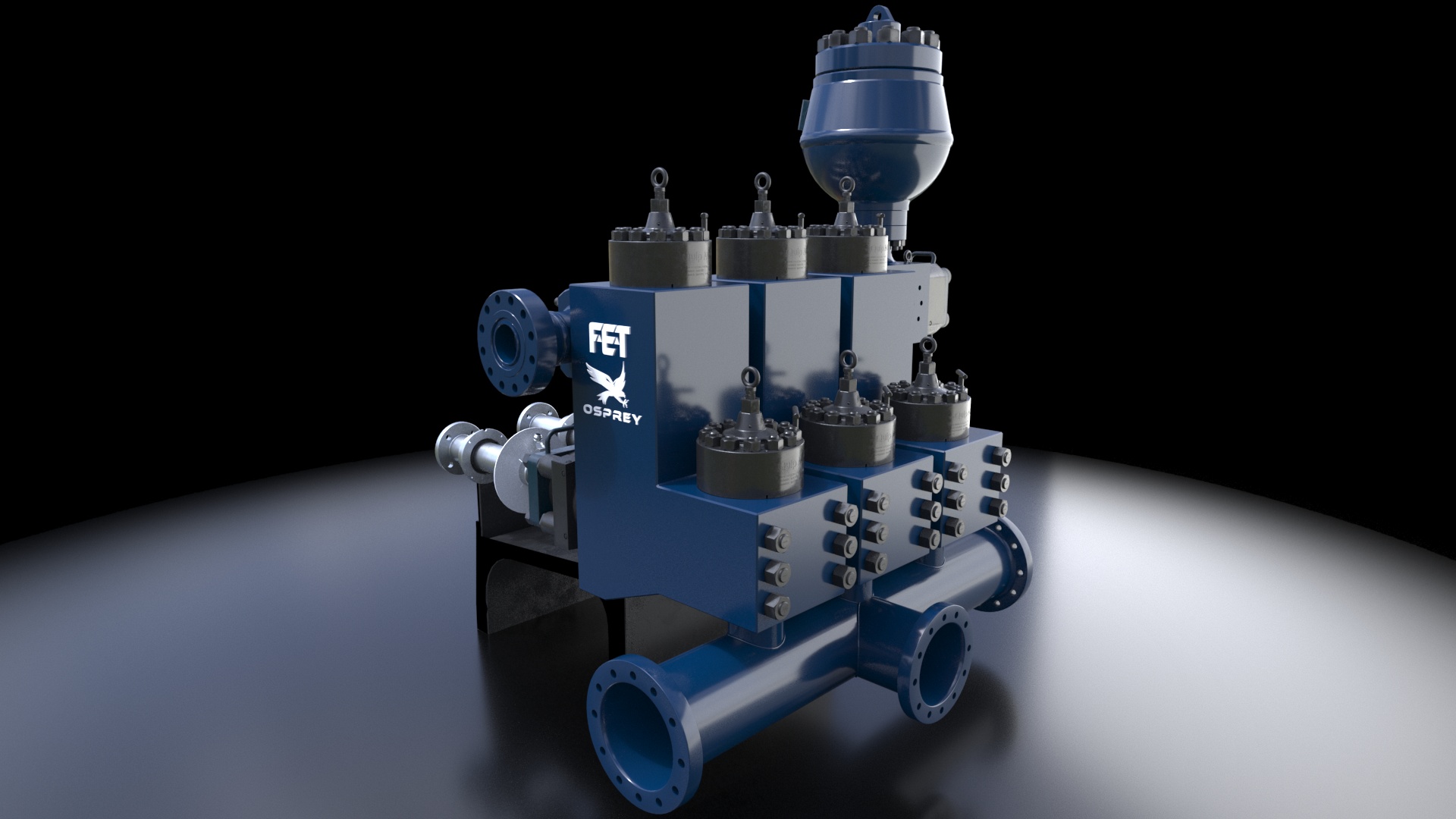
Instead of taking an existing triplex pump and trying to make it better, White Star approached the project with a clean-sheet design. The Quatro pump features a width of only 82 in. and easily fits on a standard-width trailer, a potential advantage in areas with limited space, such as on offshore rigs and in shale plays like the Marcellus. With the fluid modules sitting inside the frame, change-out time can be reduced to 23 minutes versus up to 10 hours for conventional triplex pumps. The quadraplex pump also uses a fully assembled crankshaft that requires no castings or welding. Using a crankshaft that is fully assembled and supported by modern bearing placement dramatically reduces crankshaft bending and cracking.
Additionally, the Quatro is equipped with two pulsation dampeners, one for each pair of pistons, unlike the triplex, which carries only one. This allows mud to be dampened before it gets to the strain across, creating a quieter, smoother fluid flow and reducing vibrations.

During the 1950’s the Mission” 1780 type “W” pumps were introduced to replace duplex pumps while creating the first low pressure mud system. The use of a high quality concentric type centrifugal pump allowed abrasive fluids to be mixed and transferred while reducing initial and maintenance costs for the drilling industry. The low-pressure mud system with Mission 1 780 Type “W” centrifugal pumps became the industry standard.
As well depths increased so did the need for heavier mud weights. When the mud weight began exceeding 14 ppg the need for a pump that could withstand greater horsepower loads arose. During the 1970’s Mission organized a design team that engineered the Mission Magnum. The Magnum was designed to have the same footprint, flange locations, and drive shaft diameter as the 1780 “W”. This allowed a 1780 to be replaced by a Magnum without any skid modifications. The Magnums were originally engineered with a 2-1/2″ shaft (3″ between the bearings), double row bearings with an engineered life of over 2 years at 200 HP, larger impellers and heavier frames. The Magnum allowed drilling contractors to upgrade their centrifugal pumps and mix heavier fluids.
The National Oilwell Varco” Mission centrifugal pump line has proven to be the best centrifugal design for handling abrasive mud. This pump line offers a broad selection of innovative features for a variety of routine, demanding, abrasive and corrosive applications. These pumps are designed for a wide range of flow rates, from a few gallons per minute to thousands of gallons per minute.
Each pump contains the finest materials, engineering and craftsmanship available in the industry. Described are like features of these pump lines and unique features are described on the following pages.
National Oilwell Varco utilizes unique design features developed for slurries. Three major differences from most pump designs include the concentric casing, wider impellers and increased re-circulation areas. Each feature contributes to reducing wear when handling abrasive fluids.
All of the pumps feature a concentric casing. This casing averages 37% thicker than conventional pump casings, and up to 50% thicker for the larger, mud pumping models. They are pressure rated at 1 .5 times the flange rating and are designed with a 1 /8″ erosion allowance. The concentric style casing has proven to offer the greatest pump life and reduced downtime. The walls of a concentric style casing are an equal distance from the impeller throughout the impeller circumference, which results in a smooth flow pattern. A volute style casing has a cutwater point that disturbs the fluid flow pattern creating an eddy. The concentric casing eliminates vibration, turbulence and aeration that is caused by the cutwater point in conventional volute pumps. It also reduces the high bearing loads and shaft deflection even at near shutoff flows.
The shaft is much larger in diameter than conventional pump shafts for heavy-duty performance, minimum deflection and increased operating life of the seal or packing. With a 2-1/2″ diameter at the seal area and 3″ diameter between the bearings these pumps can be direct connected or belt driven.
Adjust or replace these bearings at first sign of wear. The bearings in the crank end are babbitt lined steel shells, adjustable for wear by removing shims and easily replaced when completely worn. These bearings should be watched closely and adjusted at first signs of looseness.. You will note on series 3400, 3800, 3500, and 3900 pumps, that the shims do not completely fill the outer gap between rod and cap casting, although the connecting rod bolts are tight. This is because the faces of the shell bearings project slightly beyond the faces of the rod and cap castings, and the shims are gripped only between the faces of the bearing halves. Do not try to close this outer gap by tightening the connecting rod bolt as it will put an excessive strain on the bolts.
To check for wear, place a wrench on the top connecting rod bolt and shake the rod parallel to the crankshaft. (The pressure must be relieved from the liquid end of the pump, so that the pump"s mechanism is free to move.) If the rod bearing moves without resistance, the bearing may be too loose and need adjusting. If the bearing does need adjusting, remove shims until you cannot shake the rod, then add .005" shims one at a time until there is little side movement. Be sure to torque rod bolt nuts to proper value for each adjustment. Oil clearance should be checked with Plastigage (available in most parts stores). Wipe crankshaft journal clean of any oil, place a strip of Plastigage on the crankshaft journal and tighten rod cap to the proper torque value. Once tightened, remove rod cap and measure oil clearance with scale on Plastigage package. See oil clearance chart. (NOTE: If you are making this adjustment after having had the crossheads out, be sure that the oil holes in the rod are pointing up. The "up" side is indicated by matching numbers stamped on the cap and rod at the split between them. These numbers should be the same on each rod and should be on the top side of the crankshaft.) Rotate the shaft by hand and if there is any hard drag or tight spots in the bearing, add another 0.005" shim. After this bearing is properly adjusted, loosen bolts a few turns and repeat the above operation on the other bearings. After all bearings have been adjusted.
Torque all connecting rod bolt nuts back to proper value. Again rotate the pump by hand to check for excessive drag and tight spots. If none, the pump should be ready for operation.
If the pump cannot be rotated by hand due to the drive being enclosed, care must-be taken: not to over-tighten the bearings, since they cannot be checked by rotating the pump. When bearings are adjusted by this method, watch carefully for overheating when the pump is put into operation.
It is usually better to have a bearing a little too loose than too tight. A slightly loose bearing will cause very little trouble because of the slow operating speeds of the pump, but a tight bearing will overheat and the babbitt may melt or pull. Normal precautions must be taken to insure cleanliness of parts upon their assembly.
To check for wear, place a wrench on the top connecting rod bolt and shake the rod parallel to the crankshaft. (The pressure must be relieved from the liquid end of the pump so that the pump"s mechanism is free to move.) If the rod bearing moves without resistance, the bearing may be too loose and need adjusting. If the bearing does need adjusting, remove shims until you cannot shake the rod, then add .005" shims one at a time until there is a little side movement. Be sure to torque rod bolt nuts to proper value for each adjustment. (NOTE: If you are making this adjustment after having had the crossheads out, be sure that the oil holes in the rod are pointing up. The "up" side is indicated by matching numbers stamped on the cap and rod at the split between them. These numbers should be the same on each rod and should be on the top side of the crankshaft.) Turn the shaft by hand and if there is any hard drag or tight spots in the bearing, add another .005"" shim. After this bearing is properly adjusted, loosen bolts a few turns and repeat the above operation on the other bearings. After all bearings have been adjusted, torque all connecting rod bolt nuts back to proper amount. Again turn the pump by hand to check for excessive drag and tight spots. If none, the pump should then be ready for operation.
If the pump cannot be rotated by hand due to the drive being enclosed, the bearings may be completely adjusted by shaking the bearing on the shaft as stated above. Care must be taken not to over-tighten the bearings since they cannot be checked by rotating the pump by hand. When bearings are adjusted by this method, they must be watched carefully for overheating when the pump is put into operation.
Alternatively, plastic gauge strips, found in most parts stores may be used to adjust these bearings. It is usually better to have a bearing a little too loose than too tight. A slightly loose bearing will cause very little trouble because of the slow operating speeds of the pump, but a tight bearing will overheat and the babbitt may melt or pull. with experience, an operator can tell by feel when the bearings are properly adjusted. Normal precautions must be taken to insure cleanliness of parts upon their assembly. All wrenches used in adjusting these bearings are standard wrenches.


 8613371530291