
mud pump gear ratio calculator price

Pump Output per Stroke (PO): The calculator returns the pump output per stroke in barrels (bbl). However this can be automatically converted to other volume units (e.g. gallons or liters) via the pull-down menu.
A triplex mud (or slush) pump has three horizontal plungers (cylinders) driven off of one crankshaft. Triplex mud pumps are often used for oil drilling.

Pumps tend to be one of the biggest energy consumers in industrial operations. Pump motors, specifically, require a lot of energy. For instance, a 2500 HP triplex pump used for frac jobs can consume almost 2000 kW of power, meaning a full day of fracking can cost several thousand dollars in energy costs alone!
So, naturally, operators should want to maximize energy efficiency to get the most for their money. Even a 1% improvement in efficiency can decrease annual pumping costs by tens of thousands of dollars. The payoff is worth the effort. And if you want to remotely control your pumps, you want to keep efficiency in mind.
In this post, we’ll point you in the right direction and discuss all things related to pump efficiency. We’ll conclude with several tips for how you can maintain pumping efficiency and keep your energy costs down as much as possible.
In simple terms, pump efficiency refers to the ratio of power out to power in. It’s the mechanical power input at the pump shaft, measured in horsepower (HP), compared to the hydraulic power of the liquid output, also measured in HP. For instance, if a pump requires 1000 HP to operate and produces 800 HP of hydraulic power, it would have an efficiency of 80%.
Remember: pumps have to be driven by something, i.e., an electric or diesel motor. True pump system efficiency needs to factor in the efficiency of both the motor AND the pump.
Consequently, we need to think about how electrical power (when using electric motors) or heat power (when using combustion engines) converts into liquid power to really understand pump efficiency.
Good pump efficiency depends, of course, on pump type and size. High-quality pumps that are well-maintained can achieve efficiencies of 90% or higher, while smaller pumps tend to be less efficient. In general, if you take good care of your pumps, you should be able to achieve 70-90% pump efficiency.
Now that we have a better understanding of the pump efficiency metric, let’s talk about how to calculate it. The mechanical power of the pump, or the input power, is a property of the pump itself and will be documented during the pump setup. The output power, or hydraulic power, is calculated as the liquid flow rate multiplied by the "total head" of the system.
Remember: we’re trying to find the ratio of power in to power out. Since rations require equal units on both sides, we"ll have to do some conversions to get our hydraulic power units in HP. You"ll see how this is done in the example below.
IMPORTANT: to calculate true head, you also need to factor in the work the pump does to move fluid from the source. For example, if the source water is below the pump, you need to account for the extra work the pump puts in to draw source water upwards.
*Note - this calculation assumes the pump inlet is not pressurized and that friction losses are minimal. If the pump experiences a non-zero suction pressure, or if there is significant friction caused by the distance or material of the pipe, these should be factored in as well.
You"ll notice that the elevation head is minimal compared to the discharge pressure, and has minimal effect on the efficiency of the pump. As the elevation change increases or the discharge pressure decreases, however, elevation change will have a greater impact on total head.
Obviously, that’s a fair amount of math to get at the pump efficiency, considering all of the units conversions that need to be done. To avoid doing these calculations manually, feel free to use our simple pump efficiency calculator.
Our calculations use static variables (pump-rated horsepower and water source elevation) and dynamic variables (discharge flow and pressure). To determine pump efficiency, we need to measure the static variables only once, unless they change.
If you want to measure the true efficiency of your pump, taking energy consumption into account, you could add an electrical meter. Your meter should consist of a current transducer and voltage monitor (if using DC) for electrical motors or a fuel gauge for combustion. This would give you a true understanding of how pump efficiency affects energy consumption, and ultimately your bank account.
Up until this point, we’ve covered the ins and outs of how to determine pump efficiency. We’re now ready for the exciting stuff - how to improve pump efficiency!
One of the easiest ways to improve pump efficiency is to actually monitor pumps for signs of efficiency loss! If you monitor flow rate and discharge (output power) along with motor current or fuel consumption, you’ll notice efficiency losses as soon as they occur. Simply having pump efficiency information on hand empowers you to take action.
Another way to increase efficiency is to keep pumps well-maintained. Efficiency losses mostly come from mechanical defects in pumps, e.g., friction, leakages, and component failures. You can mitigate these issues through regular maintenance that keeps parts in working order and reveals impending failures. Of course, if you are continuously monitoring your pumps for efficiency drops, you’ll know exactly when maintenance is due.
You can also improve pump efficiency by keeping pumps lubricated at all times. Lubrication is the enemy of friction, which is the enemy of efficiency (“the enemy of my enemy is my friend…”).
A fourth way to enhance pump efficiency is to ensure your pumps and piping are sized properly for your infrastructure. Although we’re bringing this up last, it’s really the first step in any pumping operation. If your pumps and piping don’t match, no amount of lubricant or maintenance will help.
In this post, we’ve given you the full rundown when it comes to calculating and improving pump efficiency. You can now calculate, measure, and improve pump efficiency, potentially saving your business thousands of dollars annually on energy costs.
For those just getting started with pump optimization, we offer purpose-built, prepackaged solutions that will have you monitoring pump efficiency in minutes, even in hazardous environments.

We provide hydraulic components & repair services for industrial applications like paper mills, saw mills, steel mills, recycling plants, oil & gas applications and mobile applications, including construction, utility, mining, agricultural and marine equipment. This includes hydraulic pumps, motors, valves, servo/prop valves, PTOs, cylinders & parts.

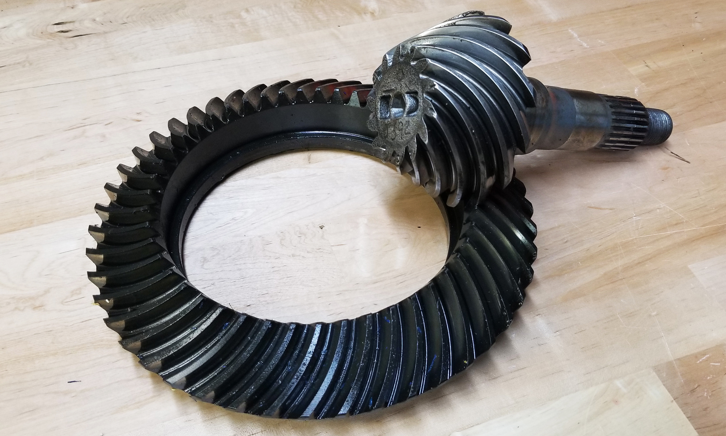
Okay, so you"ve torn your pumpkin apart and have the ring gear and pinion gear teeth count. This calculator will give you the gear ratio, just plug in the numbers.

Our mission is to provide the world with free and easy-to-use calculators to solve your daily problems. Gone are the days of looking up formulas and blasting away on your physical calculator with a notepad to figure out your problem. Now, software built into websites and apps can do that for you. This can be anything from calculating your monthly payment on a mortgage or figuring out how many calories you can eat to lose weight.

The measurement of mud motor rotation rates, and the transmission of these measurements to surface while drilling, is important for drilling optimization. In general, mud motor rotation rates are estimated from the manufacturers performance data. However, flow rates, torque, weight-on-bit and differential pressure will all vary while drilling as will the efficiency of the motor, affecting the actual rotation rate of the motor. While torque, weight and pressure can all be measured by MWD tools, the direct measurement of motor speed has proven difficult. In general it has been necessary to instrument and hardwire a motor to the MWD system in order to extract a measurement of motor speed. Such modifications result in dedicated and specialized MWD hardware.
This paper describes a means of measuring the rotation rate of a mud motor using a device that is independent of the mud motor. In essence, the dynamic signal created by the rotor is detected by vibration sensors in an MWD measurement sub in the BHA, and converted directly to motor speed. The MWD measurement sub may be remote from (i.e., not directly connected to) the motor, and therefore this system will work with any motor developed using the Moineau principle. Development and testing of the system in the laboratory and in the field are described in the paper.

Below is a list of automotive based calculators, conversion charts and converter programs available for use. Some of these are directly related to interest in the automotive and truck communities and some are of indirect interest. We have written these or provided these for educational purposes and convenience. Some are written as demonstrations of programming techniques and others have highly functional uses. We are always receptive to comments or suggestions you may have. Enjoy!
The formulae information and subsequent results of all of our converters, calculators and tables is accurate to the best of our knowledge, though we cannot guarantee it. Use it at your own risk.
When two (or more) pumps are arranged in serial their resulting pump performance curve is obtained by adding theirheads at the same flow rate as indicated in the figure below.
Centrifugal pumps in series are used to overcome larger system head loss than one pump can handle alone. for two identical pumps in series the head will be twice the head of a single pump at the same flow rate - as indicated with point 2.
With a constant flowrate the combined head moves from 1 to 2 - BUTin practice the combined head and flow rate moves along the system curve to point 3. point 3 is where the system operates with both pumps running
When two or more pumps are arranged in parallel their resulting performance curve is obtained by adding the pumps flow rates at the same head as indicated in the figure below.
Centrifugal pumps in parallel are used to overcome larger volume flows than one pump can handle alone. for two identical pumps in parallel and the head kept constant - the flow rate doubles compared to a single pump as indicated with point 2
Note! In practice the combined head and volume flow moves along the system curve as indicated from 1 to 3. point 3 is where the system operates with both pumps running
In practice, if one of the pumps in parallel or series stops, the operation point moves along the system resistance curve from point 3 to point 1 - the head and flow rate are decreased.

Researchers have shown that mud pulse telemetry technologies have gained exploration and drilling application advantages by providing cost-effective real-time data transmission in closed-loop drilling operations. Given the inherited mud pulse operation difficulties, there have been numerous communication channel efforts to improve data rate speed and transmission distance in LWD operations. As discussed in “MPT systems signal impairments”, mud pulse signal pulse transmissions are subjected to mud pump noise signals, signal attenuation and dispersion, downhole random (electrical) noises, signal echoes and reflections, drillstring rock formation and gas effects, that demand complex surface signal detection and extraction processes. A number of enhanced signal processing techniques and methods to signal coding and decoding, data compression, noise cancellation and channel equalization have led to improved MPT performance in tests and field applications. This section discusses signal-processing techniques to minimize or eliminate signal impairments on mud pulse telemetry system.
At early stages of mud pulse telemetry applications, matched filter demonstrated the ability to detect mud pulse signals in the presence of simulated or real noise. Matched filter method eliminated the mud noise effects by calculating the self-correlation coefficients of received signal mixed with noise (Marsh et al. 1988). Sharp cutoff low-pass filter was proposed to remove mud pump high frequencies and improve surface signal detection. However, matched filter method was appropriate only for limited single frequency signal modulated by frequency-shift keying (FSK) with low transmission efficiency and could not work for frequency band signals modulated by phase shift keying (PSK) (Shen et al. 2013a).
In processing noise-contaminated mud pulse signals, longer vanishing moments are used, but takes longer time for wavelet transform. The main wavelet transform method challenges include effective selection of wavelet base, scale parameters and vanishing moment; the key determinants of signal correlation coefficients used to evaluate similarities between original and processed signals. Chen et al. (2010) researched on wavelet transform and de-noising technique to obtain mud pulse signals waveform shaping and signal extraction based on the pulse-code information processing to restore pulse signal and improve SNR. Simulated discrete wavelet transform showed effective de-noise technique, downhole signal was recovered and decoded with low error rate. Namuq et al. (2013) studied mud pulse signal detection and characterization technique of non-stationary continuous pressure pulses generated by the mud siren based on the continuous Morlet wavelet transformation. In this method, generated non-stationary sinusoidal pressure pulses with varying amplitudes and frequencies used ASK and FSK modulation schemes. Simulated wavelet technique showed appropriate results for dynamic signal characteristics analysis.
As discussed in “MPT mud pump noises”, the often overlap of the mud pulses frequency spectra with the mud pump noise frequency components adds complexity to mud pulse signal detection and extraction. Real-time monitoring requirement and the non-stationary frequency characteristics made the utilization of traditional noise filtering techniques very difficult (Brandon et al. 1999). The MPT operations practical problem contains spurious frequency peaks or outliers that the standard filter design cannot effectively eliminate without the possibility of destroying some data. Therefore, to separate noise components from signal components, new filtering algorithms are compulsory.
Early development Brandon et al. (1999) proposed adaptive compensation method that use non-linear digital gain and signal averaging in the reference channel to eliminate the noise components in the primary channel. In this method, synthesized mud pulse signal and mud pump noise were generated and tested to examine the real-time digital adaptive compensation applicability. However, the method was not successfully applied due to complex noise signals where the power and the phases of the pump noises are not the same.
Jianhui et al. (2007) researched the use of two-step filtering algorithms to eliminate mud pulse signal direct current (DC) noise components and attenuate the high frequency noises. In the study, the low-pass finite impulse response (FIR) filter design was used as the DC estimator to get a zero mean signal from the received pressure waveforms while the band-pass filter was used to eliminate out-of-band mud pump frequency components. This method used center-of-gravity technique to obtain mud pulse positions of downhole signal modulated by pulse positioning modulation (PPM) scheme. Later Zhao et al. (2009) used the average filtering algorithm to decay DC noise components and a windowed limited impulse response (FIR) algorithm deployed to filter high frequency noise. Yuan and Gong (2011) studied the use of directional difference filter and band-pass filter methods to remove noise on the continuous mud pulse differential binary phase shift keying (DBPSK) modulated downhole signal. In this technique, the directional difference filter was used to eliminate mud pump and reflection noise signals in time domain while band-pass filter isolated out-of-band noise frequencies in frequency domain.
Other researchers implemented adaptive FIR digital filter using least mean square (LMS) evaluation criterion to realize the filter performances to eliminate random noise frequencies and reconstruct mud pulse signals. This technique was adopted to reduce mud pump noise and improve surface received telemetry signal detection and reliability. However, the quality of reconstructed signal depends on the signal distortion factor, which relates to the filter step-size factor. Reasonably, chosen filter step-size factor reduces the signal distortion quality. Li and Reckmann (2009) research used the reference signal fundamental frequencies and simulated mud pump harmonic frequencies passed through the LMS filter design to adaptively track pump noises. This method reduced the pump noise signals by subtracting the pump noise approximation from the received telemetry signal. Shen et al. (2013a) studied the impacts of filter step-size on signal-to-noise ratio (SNR) distortions. The study used the LMS control algorithm to adjust the adaptive filter weight coefficients on mud pulse signal modulated by differential phase shift keying (DPSK). In this technique, the same filter step-size factor numerical calculations showed that the distortion factor of reconstructed mud pressure QPSK signal is smaller than that of the mud pressure DPSK signal.
Study on electromagnetic LWD receiver’s ability to extract weak signals from large amounts of well site noise using the adaptive LMS iterative algorithm was done by (Liu 2016). Though the method is complex and not straightforward to implement, successive LMS adaptive iterations produced the LMS filter output that converges to an acceptable harmonic pump noise approximation. Researchers’ experimental and simulated results show that the modified LMS algorithm has faster convergence speed, smaller steady state and lower excess mean square error. Studies have shown that adaptive FIR LMS noise cancellation algorithm is a feasible effective technique to recover useful surface-decoded signal with reasonable information quantity and low error rate.
Different techniques which utilize two pressure sensors have been proposed to reduce or eliminate mud pump noises and recover downhole telemetry signals. During mud pressure signal generation, activated pulsar provides an uplink signal at the downhole location and the at least two sensor measurements are used to estimate the mud channel transfer function (Reckmann 2008). The telemetry signal and the first signal (pressure signal or flow rate signal) are used to activate the pulsar and provide an uplink signal at the downhole location; second signal received at the surface detectors is processed to estimate the telemetry signal; a third signal responsive to the uplink signal at a location near the downhole location is measured (Brackel 2016; Brooks 2015; Reckmann 2008, 2014). The filtering process uses the time delay between first and third signals to estimate the two signal cross-correlation (Reckmann 2014). In this method, the derived filter estimates the transfer function of the communication channel between the pressure sensor locations proximate to the mud pump noise source signals. The digital pump stroke is used to generate pump noise signal source at a sampling rate that is less than the selected receiver signal (Brackel 2016). This technique is complex as it is difficult to estimate accurately the phase difference required to give quantifiable time delay between the pump sensor and pressure sensor signals.
As mud pulse frequencies coincide with pump noise frequency in the MPT 1–20 Hz frequency operations, applications of narrow-band filter cannot effectively eliminate pump noises. Shao et al. (2017) proposed continuous mud pulse signal extraction method using dual sensor differential signal algorithm; the signal was modulated by the binary frequency-shift keying (BFSK). Based on opposite propagation direction between the downhole mud pulses and pump noises, analysis of signal convolution and Fourier transform theory signal processing methods can cancel pump noise signals using Eqs. 3 and 4. The extracted mud pulse telemetry signal in frequency domain is given by Eqs. 3 and 4 and its inverse Fourier transformation by Eq. 4. The method is feasible to solve the problem of signal extraction from pump noise,
These researches provide a novel mud pulse signal detection and extraction techniques submerged into mud pump noise, attenuation, reflections, and other noise signals as it moves through the drilling mud.

We applied a mud pulse signal to transmit the downhole measured parameters in a Logging While Drilling (LWD) system. The high-data-rate mud pulse signal was almost completely overwhelmed by noise and difficult to be identified because of the narrow pulse width, impacts of the pump noise, and the reflected wave. The wavelet transform’s multiresolution is suitable for signal denoising. In this paper, during the denoising process of the wavelet transform, we used a series of evaluation parameters to select the optimal parameter combination for denoising a mud pulse signal. We verified the feasibility of the wavelet transform denoising algorithm by analysing and processing an operational high-data-rate mud pulse signal. The decoding algorithm was available by applying self-correlation and bit synchronization. The application results through a field application showed that the processing algorithm was suitable for the high-data-rate mud pulse signal’s process.
In Measurement While Drilling/Logging While Drilling systems (MWD/LWD), mud pulse telemetry, which generally transmitted the downhole measured signal by controlling the needle’s movement to instantly block mud flow inside the drill collar [1], remains the most widely used and reliable method for transmitting data from downhole sensors to the surface [2].
Reducing the pulse width [4] can effectively increase transmitting rates; however, the mud channel (the pipe bore filled with flowing drilling mud) causes the transmitted signal to be attenuated and further distorted [5], possibly causing the signal to be overcome by noise. Figure 1 shows the original signal waveform of 0.8 s pulse width and 0.3 s pulse width.
The principal noise source which is present is due to the pressure fluctuations caused by the process of pumping the mud. The pump pressure fluctuations can be as small as a few psi with adjusted dampers and can range up to hundreds of psi (500–600) with incorrect dampers.
Mud motor is usually used for steering operations. These noises caused by the motor’s drilling can range from a few psi to hundreds of psi and will tend to occupy the frequency band below the expected mud pump noise. However, the motor “noise” will tend to be more random than pump noise.
The signal collected in practical engineering applications such as the mud pulse signal often contains a large number of nonlinear and nonstationary components, such as trend term and mutation. These nonstationary components often reflect the important characteristic of signals.
The main function of this signal detection part is to ensure that the data transmission reliably reduces the noise components of the received signal, improves the signal-to-noise ratio (SNR) before the signal is synchronously decoded, and reduces the bit error rate (BER). Synchronous decoding locates the starting position of the synchronization to identify each frame data and the transmission parameters first, then decodes the information data according to miller’s bit synchronization and decoding algorithm and outputs the 0/1 sequence data of measurement parameters last.
Because of its low efficiency, the maximum transmit rate is about 3.14 bps, which cannot meet the demand of 5 bps in a 0.2 s pulse width. Therefore, we need a new coding algorithm for high-data-rate mud telemetry.
However, during the denoising process, lower decomposition levels led to the inefficient removal of noise interference, whereas higher decomposition levels led to the filtering out of the signal as noise, so it is essential to choose an optimal decomposition level in the denoising of high-data-rate mud pulse signal.2.2.2. Selection of Threshold Function
During the denoising process of the mud pulse signal, is the original signal and is the denoised signal. We determined the optimal wavelet basis by comparing the degree of correlation coefficient between the original signal and the denoised signal under different wavelet basis.
The significance of this formula lies in fully revealing the deviation between the two vectors. The greater the calculated ρ, the better the reconfiguration effect.3.1.3. Selecting the Appropriate Wavelet Basis by SNR
Noise also resulted from the influence of various electric motors and magnetic fields in the drilling field. The composition of the mud pulse signal was complex, and we could not determine whether the pulse was valid; therefore, it was essential to remove the baseline drift before the decoding process [22]. In this paper, we applied the wavelet analysis algorithm to remove the baseline drift of the original mud pulse signal [23].
During the simulation process, only the superimposition of pump noise is considered. The test signal can almost represent the real mud pulse signal without considering the baseline drift. Parameters for generating test signals are shown below:(1)Simulated signal: the 3 bps mud pulse signal generated by the mud pulse system in laboratory environment(2)Noise: the pump noise was sampled from an actual drilling field(3)Sample rate: 2 kHz
Test signal’s characteristics in the time domain and frequency domain. (a) Simulated signal, (b) pump noise, (c) test signal, (d) spectral characteristics of test signal, and (e) spectral characteristics of simulated signal.
According to these analyses, the wavelet transform’s parameters used for high-data-rate mud pulse signal’s denoising were decomposed at level 5 and basis db8.
Based on abovementioned conclusions, a section of the original mud pulse signal with 0.3 s pulse width (3.3 bps) in Ying-X well of XX oil field in China National Petroleum Corporation (CNPC) is shown in Figure 9. The pulse signal energy was reduced, which was almost completely obscured by noise because of the narrow pulse width, the influence of pump noise, and the reflected wave.
Based on equation (10), the calculated SNR of denoised signal is 116.2661 dB. The test results showed that the mud pulse signal processing algorithm based on wavelet transform had good adaptability, achieving 0.3 s pulse width of the original signal’s denoising.
Based on the above signal processing algorithm, since 2016, the high-data-rate mud pulse system has been carried out more than 8 field tests at different conditions in Changqing Oilfield and Qinghai Oilfield of CNPC. Table 3 shows the preset parameters’ value (in HEX). As shown in Figure 13 the signal processing system filtered out the noise, and on its left part, the decoded data are the same as the preset value.
In this paper, aiming at the process of high-data-rate mud pulse signal to acquire the transmitted downhole information, we proposed a signal processing algorithm including detecting part and decoding part.
In detecting part, based on the advantages of multiresolution characteristics of wavelet transform in signal analysis, we proposed a wavelet transform algorithm for denoising high-data-rate mud pulse signals. By comparing the correlation coefficient and reconstruction factor of the signal before and after denoising, we determined an optimal parameter combination for the denoising processing of a high-data-rate mud pulse signal and demonstrated the feasibility of the algorithm shown using actual data processing.


 8613371530291