
mud pump liner calculation supplier
Rig pump output, normally in volume per stroke, of mud pumps on the rig is one of important figures that we really need to know because we will use pump out put figures to calculate many parameters such as bottom up strokes, wash out depth, tracking drilling fluid, etc. In this post, you will learn how to calculate pump out put for triplex pump and duplex pump in bothOilfield and Metric Unit.

Whether onshore or offshore, well drilling sites rely on a multitude of systems to successfully perform the drilling operation. The mud pump is a key component tasked with circulating drilling fluid under high pressure downhole. The mud pump can be divided into two key sections: the power end or crosshead and the fluid end. Proper alignment of the pump’s crosshead to the fluid end liner is necessary to maximizing piston and liner life. Misalignment contributes to
accelerated wear on both the piston and the liner, and replacing these components requires downtime of the pump. Traditional methods of inspecting alignment range from using uncalibrated wooden rods, Faro Arms and micrometers to check the vertical and horizontal alignment of the piston rod OD to the piston liner ID. These are time consuming and cumbersome techniques that are ultimately not well suited to troubleshoot and solve alignment issues.
A “Mud Pump Laser Alignment Kit” enables you to measure where the piston will run through the liner at various positions along the pump’s stroke. It will also project a laser centerline from the fluid end back towards the rear power end of the pump that can be used to determine how much shimming is required to correct any alignment issues. The kit can include either a 2-Axis receiver or a 4-Axis which accepts the laser beam and documents where it falls on the active surface of the receiver. The 4-Axis receiver can decrease alignment time by as much as 50% as it will measure angularity as well as X and Y while the 2-Axis does not and will need multiple measurement locations to get the same information. In addition, the alignment system is a non-intrusive service requiring the removal of only the piston rod which allows for much quicker service and less down time on the pump. As the mud pumps in question are located globally both on and offshore, having a small, portable system is another great advantage. Our recommendation would be Pinpoint laser System’s “Mud Pump Alignment Kit”. They are being used by many of the leading repair service companies and have been their main alignment tool for over 15 years. Manufacturers are also utilizing these for new pump set-up.

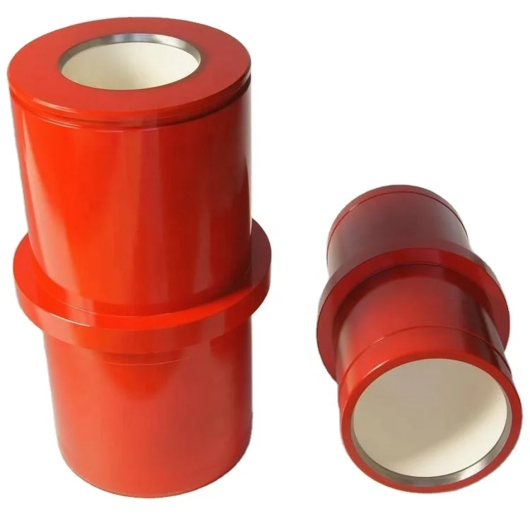
Mud pump is the "heart" of oil drilling system while mud pump liner an important disposable quick-wearing part of the fluid end. Therefore, the quality of mud pump liner will directly affect the normal operation of the drilling rig and thus the drilling costs.
Bi-metal liner is one of the most widely used types of liner. Our product combines the virtue of high strength forged steel shell and the advantage of anti-abrasive corrosion-resistant high-chromium sleeve together. The shell, including lip sleeve, is forged with high-quality carbon steel. The inner sleeve made of high-chromium cast iron is processed by centrifugal casting, the hardness of which is up to HRC 62 after heat treatment, could withstand a mud pressure of 7000 psi.
Ceramic liner is applied to well drilling operations for deep reservoir and complicated geologic situations, and is also used for offshore oil and gas development. The hardness of the working surface of the inner sleeve can reach HRC89 or more while the bending strength can be up to 1000-1200Mpa. Our ceramic liner is able to withstand a maximum pump pressure of 70Mpa. It is anti-abrasive, corrosion-resistant, heat-resistant, pressure-resistance, and is of high strength and high rigidity.
Piston assembly is one of the main parts of the fluid end of the mud pump. The volume of the working chamber alters with the reciprocating of piston, and thus realize a liquid suction and discharge through the pump valve. We are able to provide superior replaceable rubber piston and bonded piston.
Valve and seat make up a valve assembly that is the major component of the fluid end of the mud pump. It is also one of the most consumed vulnerable part during drilling.
Valve assembly is made of high-quality forged alloy steel. It has an enhanced strength by a process of carbonization at the working surface. Through precise calculation and advanced NC machining, our product can realize a favorable match between the valve body and the seat. Moreover, material is selectable as per different working situations. Thus, the lifespan of the product can be prolonged.
Valve assembly is made of high-quality forged alloy steel. It has an enhanced strength by a process of carbonization at the working surface. Through precise calculation and advanced NC machining, our product can realize a favorable match between the valve body and the seat. Moreover, material is selectable as per different working situations. Thus, the lifespan of the product can be prolonged.

Oil and Gas drilling process - Pupm output for Triplex and Duplex pumpsTriplex Pump Formula 1 PO, bbl/stk = 0.000243 x ( in) E.xample: Determine the pump output, bbl/stk, at 100% efficiency for a 7" by 12". triplex pump: PO @ 100%,= 0.000243 x 7 x12 PO @ 100% = 0.142884bbl/stk Adjust the pump output for 95% efficiency: Decimal equivalent = 95 + 100 = 0.95 PO @ 95% = 0.142884bbl/stk x 0.95 PO @ 95% = 0.13574bbl/stk Formula 2 PO, gpm = [3(D x 0.7854)S]0.00411 x SPM where D = liner diameter, in. S = stroke length, in. SPM = strokes per minute Determine the pump output, gpm, for a 7" by 12". triplex pump at 80 strokes per minute: PO, gpm = [3(7 x 0.7854) 1210.00411 x 80 PO, gpm = 1385.4456 x 0.00411 x 80 PO = 455.5 gpm
Example:Duplex Pump Formula 1 0.000324 x (liner diameter, in) x ( stroke lengh, in) = ________ bbl/stk -0.000162 x (rod diameter, in) x ( stroke lengh, in) = ________ bbl/stk Pump out put @ 100% eff = ________bbl/stk Example: Determine the output, bbl/stk, of a 5 1/2" by 14" duplex pump at 100% efficiency. Rod diameter = 2.0": 0.000324 x 5.5 x 14 = 0.137214bbl/stk -0.000162 x 2.0 x 14 = 0.009072bbl/stk Pump output @ 100% eff. = 0.128142bbl/stk Adjust pump output for 85% efficiency: Decimal equivalent = 85 100 = 0.85 PO@85%)= 0.128142bbl/stk x 0.85 PO@ 85% = 0.10892bbl/stk Formula 2
PO. bbl/stk = 0.000162 x S[2(D) - d] where S = stroke length, in. D = liner diameter, in. d = rod diameter, in. Example: Determine the output, bbl/stk, of a 5 1/2". by 14". duplex pump @ 100% efficiency. Rod diameter = 2.0in.: PO@100%=0.000162 x 14 x [ 2 (5.5) - 2 ] PO @ 100%)= 0.000162 x 14 x 56.5 PO@ 100%)= 0.128142bbl/stk Adjust pump output for 85% efficiency: PO@85%,= 0.128142bb/stkx 0.85 PO@8.5%= 0.10892bbl/stk Metric calculation Pump output, liter/min = pump output. liter/stk x pump speed, spm. S.I. units calculation Pump output, m/min = pump output, liter/stk x pump speed, spm. Mud Pumps Mud pumps drive the mud around the drilling system. Depending on liner size availability they can be set up to provide high pressure and low flow rate, or low pressure and high flow rate. Analysis of the application and running the Drill Bits hydraulics program will indicate which liners to recommend. Finding the specification of the mud pumps allows flow rate to be calculated from pump stroke rate, SPM. Information requiredo Pump manufacturer o Number of pumps o Liner size and gallons per revolution Weight As a drill bit cutting structure wears more weight will be required to achieve the same RoP in a homogenous formation. PDC wear flats, worn inserts and worn milled tooth teeth will make the bit drill less efficiently. Increase weight in increments of 2,000lbs approx. In general, weight should be applied before excessive rotary speed so that the cutting structure maintains a significant depth of cut to stabilise the bit and prevent whirl. If downhole weight measurements are available they can be used in combination with surface measurements to gain a more accurate representation of what is happening in the well bore.

Kverneland, Hege, Kyllingstad, Åge, and Magne Moe. "Development and Performance Testing of the Hex Mud Pump." Paper presented at the SPE/IADC Drilling Conference, Amsterdam, Netherlands, February 2003. doi: https://doi.org/10.2118/79831-MS

Mud Pump Liner Market Size is projected to Reach Multimillion USD by 2028, In comparison to 2022, at unexpected CAGR during the forecast Period 2023-2028.
1. Does this report consider the impact of COVID-19 and the Russia-Ukraine war on the Mud Pump Liner market?Yes. As the COVID-19 and the Russia-Ukraine war are profoundly affecting the global supply chain relationship and raw material price system, we have definitely taken them into consideration throughout the research, and in Chapters, we elaborate at full length on the impact of the pandemic and the war on the Mud Pump Liner Industry
This research report is the result of an extensive primary and secondary research effort into the Mud Pump Liner market. It provides a thorough overview of the market"s current and future objectives, along with a competitive analysis of the industry, broken down by application, type and regional trends. It also provides a dashboard overview of the past and present performance of leading companies. A variety of methodologies and analyses are used in the research to ensure accurate and comprehensive information about the Mud Pump Liner Market.
The Global Mud Pump Liner market is anticipated to rise at a considerable rate during the forecast period, between 2022 and 2028. In 2021, the market is growing at a steady rate and with the rising adoption of strategies by key players, the market is expected to rise over the projected horizon.
The global Mud Pump Liner market is projected to reach USD million by 2028 from an estimated USD million in 2022, at a Impressive CAGR during 2023 and 2028.
North American market for Mud Pump Liner is estimated to increase from USD million in 2022 to reach USD million by 2028, at a Impressive CAGR during the forecast period of 2023 through 2028.
Asia-Pacific market for Mud Pump Liner is estimated to increase from USD million in 2022 to reach USD million by 2028, at a Impressive CAGR during the forecast period of 2022 through 2028.
The major global companies of Mud Pump Liner include Dezhou LandA Petroleum Machinery Co., Ltd, Forum Energy Technologies, Inc, NOV Inc, Premium Oilfield Technologies, Dongying Lake Petroleum Technology CO., Ltd, SHANDONG SAIGAO GROUP CORPORATION, Titan Oil Tools, Taisheng Tech and PETAL SA and etc. In 2021, the world"s top three vendors accounted for approximately Percent of the revenue.
The global market for Mud Pump Liner in Oil and Gas is estimated to increase from USD million in 2022 to USD million by 2028, at a Impressive CAGR during the forecast period of 2022 through 2028.
Considering the economic change due to COVID-19 and Russia-Ukraine War Influence, Ceramics, which accounted for Percent of the global market of Mud Pump Liner in 2021, is expected to reach million USD by 2028, growing at a revised Impressive CAGR from 2022 to 2028.
This report aims to provide a comprehensive presentation of the global market for Mud Pump Liner, with both quantitative and qualitative analysis, to help readers develop business/growth strategies, assess the market competitive situation, analyze their position in the current marketplace, and make informed business decisions regarding Mud Pump Liner.
The Mud Pump Liner market size, estimations, and forecasts are provided in terms of output/shipments (K Units) and revenue (USD millions), considering 2021 as the base year, with history and forecast data for the period from 2017 to 2028. This report segments the global Mud Pump Liner market comprehensively. Regional market sizes, concerning products by types, by application, and by players, are also provided. The influence of COVID-19 and the Russia-Ukraine War were considered while estimating market sizes.
The report will help the Mud Pump Liner manufacturers, new entrants, and industry chain related companies in this market with information on the revenues, production, and average price for the overall market and the sub-segments across the different segments, by company, product type, application, and regions.
This Mud Pump Liner Market Research/Analysis Report Contains Answers to your following Questions ● What are the global trends in the Mud Pump Liner market? Would the market witness an increase or decline in the demand in the coming years?
● What is the estimated demand for different types of products in Mud Pump Liner? What are the upcoming industry applications and trends for Mud Pump Liner market?
● What Are Projections of Global Mud Pump Liner Industry Considering Capacity, Production and Production Value? What Will Be the Estimation of Cost and Profit? What Will Be Market Share, Supply and Consumption? What about Import and Export?
● How big is the opportunity for the Mud Pump Liner market? How will the increasing adoption of Mud Pump Liner for mining impact the growth rate of the overall market?

Lake Petro provides high quality Mud Pump Parts including Mud Pump Liners, Mud Pump Fluid End Module, piston, Valve and Seat etc. With more than 10 years of experience in the oil and gas industry, we are dedicated to help and support our loyal clients with the most cost-effective and quality Liners and Pistons. We also provide mud pump price and mud pump for sale.
We offer Liners with Ceramic (Zirconia and Aluminium oxide) and Steel (Metal and Bi-metal) materials for all common brands of the mud pump and triplex mud pump.
Bi-metal liners (double metal liners) are made of forged steel shell and wear-resistant sleeve of high chromium iron. In the production process, the size accuracy should be strictly controlled, which can ensure that they can be easily and stably installed. The inner sleeve with high finish and hardness is wear-resistant, corrosion-resistant and has a long service life. The bi-metal liners are suitable for a lot of bad working conditions. Its service life is more than 800 hours.
Ceramic Liners are made of a ceramic inner sleeve and a forged steel outer shell. The service life of ceramic liners is about 4000 to 10000 hours, the minimum time is at least 2000 hours, which is a lot more than bi-metal liners. Because of the phase transformation toughen technology, the ceramic liners have the features of wear-resistance, erosion-resistance, high-pressure-resistance, high hardness and strength. Zirconia type and Alumina type are common type of ceramic sleeve. Compared with Alumina type, Zirconia type liners have better toughness properties and a much longer service life. Piston wear and water consumption for lubrication can be reduced as well.
Seal Rings for Liner packing are also important. Liner Seal Rings is designed and made with hard corner which is an integral part of seal rings and soft nitrile element rubber center. We could provide reliable liner Seal Rings for our customers could order them at the same time.
All Lake Petro liner products are interchangeable with O.E.M. products. Meanwhile, we provide customized Liners according to drawings. Our liners, also with our other mud pump spares, are supplied for use in Honghua, F-Series, Bomco, Emsco and National lines of triplex drilling pumps. Let Lake Petro be your one-stop shop for your whole fleet of pumps. Please refer to “Suitable Pump Models” Lable for more details.

This approach works well but relying on a printed reference is not without the risk since the wrong value can still be selected from the fine print of a reference table, or the reference document can be damaged or lost (e.g., dropped in the mud pit) altogether.
So, let’s address the alternative approach of using simple mathematical formulas to determine the same information. Although the reliance on a single sheet of paper to obtain the needed value is avoided with this approach, the potential for human error or miscalculation remains, meaning regardless of the approach, great care in determining such values is prudent.
As we consider the various calculations that enable us to determine the values of length, weight, pressure, volume, flow velocity, etc., we should remain mindful of the units of measure we’re dealing with. The groundwater industry uses units of measure that are somewhat intermingled with other units from associated disciplines such as engineering, surface water hydrology, and the oil and gas drilling industry.
We want to know the volume of material (filter pack sand, cement grout, etc.) that is to be placed in the annulus to assure the annular void has been properly and completely filled (Figure 1). The conceptual diagram showing the variables used for calculating an annular void is shown in Figure 2, and the formula for the annular volume calculation is:
In this calculation, the “d” value is the diameter of the casing or pipe diameter, and the “D” value is the borehole diameter (Figure 2). The sump area below the base of the casing has only one diameter in the open borehole, so the “d” value is omitted, and the formula just becomes:
If excessive hydraulic pressures are exerted on a well casing, it will collapse. We generally know the collapse strength of the well casing from the casing supplier or from standard references such as the charts in American Water Works Association Standard A100. The hydraulic pressures applied to the outside of the well casing depend on the density of the liquid and the depth of submergence (Figure 1). Applying the fluid density (measured in the field) and depth (Figure 2), the formula for hydraulic pressure head calculation is:
The hydraulic head formula is applicable to the hydraulic pressure head for any liquid, but we most commonly use this calculation during cement seal installation, since cement grout is generally the heaviest liquid being introduced to the annulus during well construction.
The intermediate casing can be sealed using the pressure grouting technique (Figure 3) to pump cement slurry down through the drill pipe and out to the annulus through a float shoe (a drillable check valve connected to the base of the casing). The inside of the intermediate casing is kept full of water during the cement placement to equilibrate hydraulic pressures inside and outside the casing. After the intermediate casing is sealed with the pressure grouted cement, the float shoe can be drilled out and the borehole advanced for installation of the screen and filter pack in the lower part of the well.
Floating of a casing string introduces serious logistical and safety hazards and creates significant disruption to the integrity of the annular seal. The potential for floating of the intermediate casing can be easily mitigated by securing it at the land surface, but the driller needs to know that this is required before the cementing operations begin. Thus, a buoyancy calculation is a good idea prior to pressure grouting operations as illustrated in Figure 3.
The buoyancy calculation is more of a conceptual comparison than a pure mathematical formula. This analysis involves some visualization be made on the part of the groundwater professional.
If you apply the weight calculations for a 400-foot-long steel casing with a 16-inch diameter and a 5/16-inch wall thickness, which is filled with water, you’ll see that the downward force in this example is only 52,982 pounds. Thus, the casing in this example will float. The lesson from this counterintuitive scenario is that a casing can actually float. (I’ve seen it happen, and trust me, you don’t want to).
There are several calculations that are commonly applied by drilling fluid engineers (mud engineers) to determine the time period required for the fluid to move from one location in the borehole to another. Some of the more common equations are described below.
The uphole velocity calculation provides a determination of the speed at which the drilling mud will flow as it moves up the borehole. For direct air rotary or reverse circulation drilling methods, the uphole velocity is high, so this calculation is generally applicable only for the direct mud-rotary drilling method. The formula for uphole velocity is:
Notice the uphole velocity formula is similar to the annular volume formula in that both those calculations use the factor (D2 – d2) to address the cross-sectional area of the annulus. However, the constants in these two formulas are different (0.005454 versus 24.51), which can be confusing. Keep in mind, however, that the constants primarily just provide unit conversions.
Thebottoms-up time calculation enables us to determine the time period for the drilling fluid (and the cuttings it is carrying) to travel from the drill bit up to the land surface. This is illustrated in Figure 6(A).
We can calculate the bottoms-up time by using the uphole velocity formula with the borehole depth and drilling mud flow rate plugged in, but that flow rate is being generated by the mud pump, and positive displacement mud pumps (duplex or triplex) are almost never equipped with a flow meter. To determine the flow coming from the mud pump, we can use the formulas:
Remember the strokes are counted in both the forward and backward directions on a duplex pump, but only in the forward direction on a triplex pump. Drillers often have reference charts that provide oilfield barrels per stroke (bbl/stroke), which can be converted to gpm by timing the strokes per minute and converting barrels to gallons (1 barrel = 42 gallons).
The round-trip time enables us to see the result of drilling fluid additives, as indicated by the return flow of fluids at the land surface, as is illustrated in Figure 6(B). The round-trip time calculation is the same as bottoms-up time, but with the travel time of fluid to displace the drill pipe added in.
A specified volume of drilling fluids (called a pill) can be circulated to a particular depth interval within the borehole (called spotting), so that the additives in the pill of drilling mud can address the borehole problem at a particular depth of the borehole. This is shown in Figure 6(C).
The calculation for time required to spot a pill of drillingfluid involves determining the pumping time (at the calculated flow rate) required to displace the fluid so that the drilling mud additives are located adjacent to the problematic interval. This approach is used by mud engineers to address problems such as lost circulation or stuck drill pipe.
The formulas and calculations provided in this column and elsewhere provide important tools for us to quantify the variables we need for water well design and construction. However, it is important to remember that “doing the math” is not a replacement for applying professional knowledge and consideration to determine whether the mathematical result makes common sense.


 8613371530291