
mud pump liner cooling system pricelist
Now we would like to introduce our new liner cooling system (stand alone for N O N MHWirth Mud Pumps as well) for your mud pumps. The three liners of a mud pump are cooled with circulated fresh water by the Liner Cooling System.
The three liners of a mud pump are cooled by the Liner Cooling System. Circulated fresh water is fed by an electrically driven centrifugal pump from a stainless steel tank via piping to the liner cooling nozzle system. The shape of the bottom of the tank has been chosen so that dirt can settle down easily.
The system can be placed anywhere. The system is used if the standard cooling system is to difficult to maintain. A backup system for seawater cooling allows closing the fresh water circuit and connecting seawater to cool the liners with seawater from an external source (provided by others).
NOV 12-P-160 Mud Pump is rated at 1600 input horsepower (1193 kw) at 120 strokes per minute, with a 12-inch (304.8 mm) stroke. Multiple liner sizes allow pressures and volumes to handle circulation requirements in deep drilling applications.
Flexibility: Compact engineering provides higher efficiency in less space. The NOV 12-P-160 Triplex Mud Pump light weight and flexible design make it easily adaptable to a variety of rig configurations. This provides flexibility as drilling requirements and conditions change.
Fluid End Modules: NOV offers a choice of fluid end modules and valve covers for every P Series pump model to select the fluid end module that exactly matches drilling requirements. All pump models can be equipped with either the standard or premium forged, two-piece interchangeable fluid modules

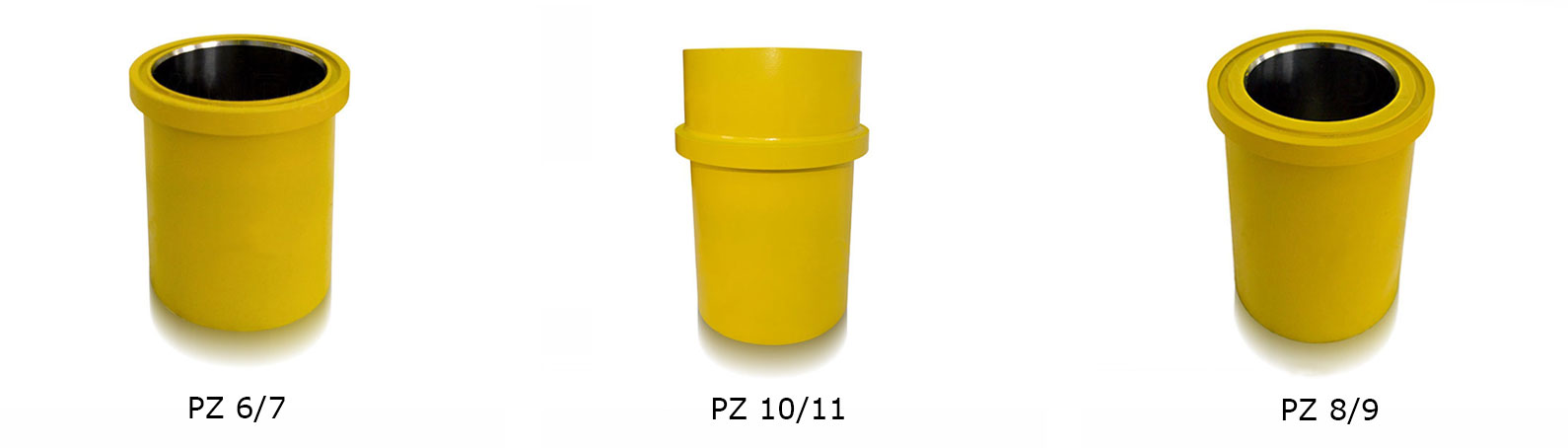
Chrome-Iron Liners . . . . . . . . . . . . . . . . . . . . . . . . . . . . . . . . . . . . . . . . . . . . . . . . . . . . . . . . . . . . . . . . . . . 6
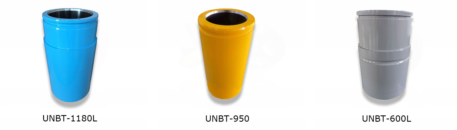
Zirconia-Ceramic Liners . . . . . . . . . . . . . . . . . . . . . . . . . . . . . . . . . . . . . . . . . . . . . . . . . . . . . . . . . . . . . . . 7
Mud-Pump Gear Sets . . . . . . . . . . . . . . . . . . . . . . . . . . . . . . . . . . . . . . . . . . . . . . . . . . . . . . . . . . . . . . . . . 13

A Mud pump features robust reciprocating pumping technology for mud circulation on the drilling array. Reciprocating pumps follow the conventional mechanism of the auto engine.
Having a crosshead crankshaft gear makes the mud pump mechanism more effective. And the specific placement of the connecting rod helps the piston to play its role.
And in this position, a cooling spray of water on the pump’s pistons helps it work better. As well as other moving portions like liners also work better with cooling water spray.
The mud pump works as a virtual device featured in the well drilling kit. Unlike a stand-alone device, this kind of pump works as major equipment of robust drilling equipment.
Both output and input fluid flows through the direct pipeline towards the drilling string. The advanced connectivity with structured fixtures of the borehole helps a mud pump to perform the best.
In the case of remote locations, the mechanism of diesel motors suits this kind of pumping unit. On the availability of DC motor kits, a mud pump features electric energy driven AC motors.
The surface of this kind of deep well can be spacious up to 10 miles. So, in these cases, a mud pump must work on the 10 miles below the water surface.
The types of a mud pump depend on its specific combo of components. According to the requirements of the clients, this pump features the best equipment.
The number of working ends of a pump’s piston defines the pattern of action. Having a single working end of the piston, a Single-acting mud pump can use only one direction.
For a wide range of drilling applications, this kind of pumping unit works the best. In these applications, a pump needs to generate a high amount of pressure.
The Duplex mud pump’s competent mechanism helps to ensure the standard mud circulation as it can reach from the mud picking system to the bottom point of the well.
All these components provide the best performance executing the top-tier mechanism. In case of severe vibration, this pumping unit requires a suction unit.
Maintenance is a vital thing to boost the lifespan of a pump. If you go through the following essential key points, you will learn how to enhance a mud pump’s performance.
Regular servicing is a standard part of maintenance for any mechanical unit. But, most of the maintenance shop complains about the abuse of pumping components without any oil treatment.
Checking and changing the oil daily makes your mud pump more efficient. If you detect any mud or water contamination in existing oil, don’t hesitate to change it.
So, users should take care of the gear end from mud deposits. Otherwise, it will ruin pony rod packing. It’s one kind of mechanical failure, which can shred pistons and liners.
Fluid for Liner wash can contain different fluids. But experts recommend using clean water. In extreme conditions of coldness, using RV antifreeze provides the best result.
This kind of potent system contains a tank along with a spray bar and a small pumping unit. Using the spray bar, the tank moves out the fluid from the tank.
Always remember where a mud pump deals with drilling fluid, it should be free of solids. The drilling fluid can be raw water or other combination of liquid. But it needs to be solids-free.
For the recycling process of your fluid, always prefer a standard mud recycling system. As well as checking the reliable content throughout the day enhance the performance of your system.
A triplex mud pump works with minimal suction pressure. One thing you need to remember is the maintenance of this suction pressure with consistency during application.

Mystique Mud pump Coolant and Lubricant extends mud pump liner and piston life and provides internal lubrication and extra cooling to the coolant system of mud pumps. It extends the life of all liners, even ceramic. Mystique will not cause corrosion or rusting of iron, and is safe with all alloys. Recommened dilution rate of 12.5%. (25 gallons will treat a 200-gallon system.) For use on closed systems.

The concept of the lurry pump and mud pump is very close, many people do not know what the difference is. Although both mud pump and slurry pump are impurity pumps, if you fully understand these two types of pumps, you can clearly distinguish them from the application and the characteristics of the conveying medium. In this article, we will introduce the differences between mud pump and slurry pump from 4 aspects.
Conveying Medium. The slurry pump is mainly used in the mining industry, and its wear resistance is relatively strong. So it can not only transport slag-containing mud, but also mud. Slurry pumps are usually made of cast iron, and the pumps have low wear resistance. Therefore, mud pumps are often used to transport mud containing suspended particles. When the slurry pump is working, the pump parts are susceptible to impact, wear and corrosion. Therefore, the bushing of the slurry pump adopts wear-resistant materials, such as high-chromium alloy, rubber, etc. The use of wear-resistant materials can effectively reduce the wear parts of the pump. Therefore, most of the slurry pumps on the market are wear-resistant slurry pumps.
Working Principle. For the mud pump, the motor drives the piston to move through the connecting rod mechanism, which causes the change of the volume of the sealed cavity of the mud pump. And make the pressure difference inside and outside the pump change. Finally, the process of water absorption and drainage is completed. When the slurry pump is working, the motor drives the impeller to rotate, thereby increasing the kinetic energy of the slurry. At the same time, the slurry flows to the edge of the impeller due to inertia, and is discharged from the drain pipe at a high speed.
Application. The slurry pump is widely used for solid slurry transportation in metallurgy, dredging, mining, electric power, coal and other industries. Mud pumps are mainly used in papermaking, drilling, winemaking, pharmaceutical and other industries to transport suspensions.
Auxiliary Equipment. Auxiliary equipment is required when using a mud pump, but not a slurry pump. The mud pump often needs to be used together with the high pressure water pump. The high-pressure pump sends water at a higher pressure than the mud pump to the leak-proof packing. Then protect the packaging. Otherwise, it is easy to wear the sealing parts. However, the wear-resistant pulp pump can complete the conveying work independently, and does not need to be equipped with other auxiliary equipment.
In short, the mud pump not only has stronger wear resistance, but also has a stronger ability to transport particles. Generally, the capacity of the slurry pump is larger than that of the slurry pump, and it is mainly suitable for the washing of coal and metal ore. The mud pump is more suitable for the occasion of daily life. ATO shop provides different models vertical mud pump, such as 2 inch mud pump, 3 inch mud pump, 4 inch mud pump and so on.
Closed loop pressurized freshwater liner wash system, complete with integral water cooling tank equipped with centrifugal pump and driven by explosion proof electric motor
Belt drive transmission: two each motor sheaves and QD mounted pump sheaves; banded Kevlar Vbelts; belt guards; for use with AC drive motors c/w 20HP blower assemblies

The piston is one of the parts that most easily become worn out and experience failure in mud pumps for well drilling. By imitating the body surface morphology of the dung beetle, this paper proposed a new type (BW-160) of mud pump piston that had a dimpled shape in the regular layout on the piston leather cup surface and carried out a performance test on the self-built test rig. Firstly, the influence of different dimple diameters on the service life of the piston was analyzed. Secondly, the analysis of the influence of the dimple central included angle on the service life of the piston under the same dimple area density was obtained. Thirdly, the wear of the new type of piston under the same wear time was analyzed. The experimental results indicated that the service life of the piston with dimples on the surface was longer than that of L-Standard pistons, and the maximum increase in the value of service life was 92.06%. Finally, the Workbench module of the software ANSYS was used to discuss the wear-resisting mechanism of the new type of piston.
The mud pump is the “heart” of the drilling system [1]. It has been found that about 80% of mud pump failures are caused by piston wear. Wear is the primary cause of mud pump piston failure, and improving the wear-resisting performance of the piston-cylinder friction pair has become the key factor to improve the service life of piston.
Most of the researchers mainly improve the service life of piston through structural design, shape selection, and material usage [1, 2]. However, the structure of mud pump piston has been essentially fixed. The service life of piston is improved by increasing piston parts and changing the structures of the pistons. However, the methods have many disadvantages, for example, complicating the entire structure, making piston installation and change difficult, increasing production and processing costs, and so on. All piston leather cup lips use rubber materials, and the material of the root part of the piston leather cup is nylon or fabric; many factors restrict piston service life by changing piston materials [3]. Improving the component wear resistance through surface texturing has been extensively applied in engineering. Under multiple lubricating conditions, Etsion has studied the wear performance of the laser surface texturing of end face seal and reciprocating automotive components [4–6]. Ren et al. have researched the surface functional structure from the biomimetic perspective for many years and pointed out that a nonsmooth surface structure could improve the wear resistance property of a friction pair [7, 8]. Our group has investigated the service life and wear resistance of the striped mud pump piston, and the optimal structure parameters of the bionic strip piston have improved piston service life by 81.5% [9]. Wu et al. have exploited an internal combustion engine piston skirt with a dimpled surface, and the bionic piston has showed a 90% decrease in the average wear mass loss in contrast with the standard piston [10]. Gao et al. have developed bionic drills using bionic nonsmooth theory. Compared with the ordinary drills, the bionic drills have showed a 44% increase in drilling rate and a 74% improvement in service life [11]. The present researches indicate that microstructures, like superficial dimples and stripes, contribute to constituting dynamic pressure to improve the surface load-carrying capacity and the wear resistance of the friction pair [12–21].
In nature, insects have developed the excellent wear-resistant property in the span of billions of years. For instance, the partial body surface of the dung beetle shows an irregularly dimpled textured surface with the excellent wear-resistant property that is conducive to its living environment [7, 8, 22]. The dung beetle, which is constantly active in the soil, shows a body surface dimple structure that offers superior drag reduction. These dimples effectively reduce the contact area between the body surface and the soil. Moreover, the friction force is reduced. Therefore, the dung beetle with the nonsmooth structure provides the inspiration to design the bionic mud pump piston. This paper proposed a new type of piston with dimpled morphology on its surface and conducted a comparative and experimental study of different surface dimpled shapes, thus opening up a new potential to improve the service life of the mud pump piston.
A closed-loop circulatory system was used in the test rig, which was built according to the national standard with specific test requirements. The test rig consisted of triplex single-acting mud pump, mud tank, in-and-out pipeline, reducer valve, flow meter, pressure gauge, and its principle, as shown in Figure 1. Both the pressure and working stroke of the BW-160 mud pump are smaller than those of the large-scale mud pump, but their operating principles, structures, and working processes are identical. Therefore, the test selected a relatively small BW-160 triplex single-acting mud pump piston as a research object, and the test results and conclusion were applicable to large-scale mud pump pistons. The cylinder diameter, working stroke, reciprocating motion velocity of piston, maximum flow quantity, and working pressure of the BW-160 triplex single-acting mud pump were 70 mm, 70 mm, 130 times/min, 160 L/min, and 0.8–1.2 MPa, respectively.
The mud pump used in the test consisted of water, bentonite (meeting the API standard), and quartz sand with a diameter of 0.3–0.5 mm according to actual working conditions. The specific gravity of the prepared mud was 1.306, and its sediment concentration was 2.13%. Whether mud leakage existed at the venthole in the tail of the cylinder liner of the mud pump was taken as the standard of piston failure. Observation was made every other half an hour during the test process. It was judged that the piston in the cylinder failed when mud leaked continuously; its service life was recorded, and then it was replaced with the new test piston and cylinder liner. The BW-160 mud pump is a triplex single-acting mud pump. The wear test of three pistons could be simultaneously conducted.
The mud pump piston used in the test consisted of a steel core, leather cup, pressing plate, and clamp spring. The leather cup consisted of the lip part of polyurethane rubber and the root part of nylon; the outer diameter on the front end of the piston was 73 mm, and the outer diameter of the piston tail was 70 mm, as shown in Figure 2. We proceeded in two parts during the design of the dimpled layout pattern because the piston leather cup consisted of two parts whose materials were different. The dimples at the lip part of the leather cup adopted an isosceles triangle layout pattern, and the dimples at the root part were arranged at the central part of its axial length, as shown in Figure 3(a). Dimple diameter (D, D′), distance (L), depth (h), and central included angle (α) are shown in Figure 3. The dimples on the piston surface were processed by the CNC machining center. Since then, the residual debris inside the dimples was cleaned.
Table 1 shows that average service lives of L-Standard, L-D1, L-D2, and L-D3 were 54.67 h, 57.17 h, 76.83 h, and 87.83 h, respectively. Therefore, the mud pump pistons with dimples provide longer service life than the L-Standard piston. As the dimple diameter increases, the piston service life was improved, and the largest percentage increase of the service life was 60.65%. The service life of the L-D4 piston was about 81.17 h, which increased by 7.94% compared with that of the L-D2 piston, indicating that the piston with dimples at the leather cup root could improve piston service life.
Figure 4 illustrates the surface wear patterns of pistons with different dimple diameters in the service life test. Figures 4(a) and 4(a′) show wear patterns on the surface of the L-Standard piston. This figure shows that intensive scratches existed in parallel arrangement on the piston leather cup surface, enabling high-pressure mud to move along the scratches from one end of the piston to the other easily, which accelerated the abrasive wear failure with the abrasive particles of the piston. Figures 4(b), 4(b′), 4(c), 4(c′), 4(d), and 4(d′) show the wear patterns of the leather cup surfaces of L-D1, L-D2, and L-D3 pistons, respectively. Figures 4(b), 4(b′), 4(c), 4(c′), 4(d), and 4(d′) show that the scratches on the leather cup surface became shallower and sparser and the surface wear patterns improved more obviously as the dimple diameter increased. If the piston leather cup surface strength was not affected to an extent as the dimple diameter increased, the reduced wear zone near the dimple would become greater and greater, indicating that the existence of dimples changed the lubricating status of the leather cup surface, their influence on nearby dimpled parts was more obvious, and they played active roles in improving the service life of the piston.
Figure 5 displays the wear patterns of the leather cup root parts of the L-D4 and L-D2 test pistons. The wear patterns of the nylon root parts of the L-D4 pistons are fewer than those of the L-D2 pistons, as shown in Figure 5. When the leather cup squeezed out high-pressure mud as driven by the piston steel core, it experienced radial squeezing while experiencing axial wear. Therefore, the area with the most serious wear was the piston leather cup root part, and the friction force at the leather cup root was much greater than that at the other areas. The rapid wear at the root decreased the piston load-carrying capacity and then affected the service life of piston. The dimples at the piston leather cup root could reduce the wear of the piston leather cup root and improve the service life of piston.
Figure 6 shows the surface wear patterns of the L-S1 and L-S2 test pistons. In Figures 6(a) and 6(a′), the scratches on the piston leather cup surface became sparse and shallow in the dimpled area. Figures 6(b) and 6(b′) show that the wear was slight in the area close to the dimples. The farther the scratches were from the dimpled area, the denser and deeper the scratches would be. The L-S1 piston had a small dimple central included angle, which was arranged more closely on the piston surface. The lubricating effects of oil storage in each row of dimples were overlaid very well, which was equivalent to amplifying the effect of each row of dimples in Figure 6(b), making the wear on the whole piston leather cup surface slight, preventing the entry of high-pressure mud into the frictional interface, and lengthening the service life of piston.
During the operation of the mud pump piston, the outside surface of the piston leather cup comes in contact with the inner wall of the cylinder liner and simultaneously moves to push the mud. The lip part of the piston leather cup mainly participated in the piston wear and exerted a sealing effect, while the piston root part mainly exerted centralizing and transitional effects. In the mud discharge stroke, the lip part of the piston experienced a “centripetal effect,” and a gap was generated between the lip part and the cylinder liner. The greater the contact pressure between the lip part and cylinder liner of the piston was, the smaller the gap was, and the entry of high-pressure mud into the contact surface between the piston and cylinder liner was more difficult. The piston root easily experienced squeezing under high pressure, and the smaller the equivalent stress caused by the piston root was, the more difficult the squeezing to occur. Hence, the contact pressure at the lip part of the piston and the equivalent stress at the root were analyzed, and they would provide a theoretical basis for the piston wear-resisting mechanism. The ANSYS Workbench module was used to perform a comparative analysis between the contact pressure at the lip part and the equivalent stress at the root of the three kinds of pistons (i.e., L-Standard piston, L-S1 piston, and L-D1 piston). The service life of the L-S1 piston exhibited the best improvement effect, whereas that of the L-D1 piston demonstrated the worst improvement effect. The piston adopted a 1 mm hexahedral grid, and the grid nodes and elements are as shown in Table 4.
The contact pressure nephograms of the three pistons indicate that the dimpled structure on the piston surface changed the distribution state of contact pressure. Three nodes were selected at the same position of each piston to obtain the contact pressure values. The node positions are shown in Figure 8(c), and the average pressure value of three nodes was the pressure value at the lip part of this piston. The contact pressure value of the L-Standard piston was 0.6027 MPa and that of the L-D1 and L-S1 pistons was 0.6840 MPa and 1.0994 MPa, respectively. Compared with the L-Standard piston, the contact pressure at the lip part of the L-S1 piston increased, the gap between the piston and cylinder liner became small, which could effectively prevent abrasive particles from participating in the wear and resulting in piston failure, and there was greater improvement in the service life of piston. The contact pressure of the L-D1 piston did not increase too much, and the degree of improvement of the piston service life was not obvious.
The lubricating oil on the mud pump piston surface could reduce the wear of piston and cylinder liner and improve the service life of pistons with the reciprocating movement. The lubricating oil would eventually run off and lose lubricating effect, which would result in piston wear. The finite element fluid dynamics software CFX was used to establish the fluid domain model of the dimpled and L-Standard pistons and analyze the lubricating state on the piston surface. The piston surface streamlines are shown in Figure 10. This figure shows that the lubricating fluid did not experience truncation or backflow phenomenon when passing the surface of the L-Standard piston. When the lubricating fluid flowed through the surface of the dimpled piston, it presented a noncontinuous process. Its flow velocity at the dimpled structure slowed down obviously because it was blocked by the dimpled structure.
Figure 11 shows the piston cross section streamline. This figure shows that the existence of dimples changed the distribution status of the lubricating flow fields on the contact surface between the piston and cylinder liner. The lubricating oil entered the dimpled structure in a large quantity, and the flow velocity slowed down. The dimpled structure on the piston surface enlarged the storage space of the lubricating oil and made it difficult for the lubricating oil inside the dimpled structure to be taken away by the cylinder liner to improve the lubricating conditions of the friction pair interface, reduce the frictional resistance between the piston and cylinder liner, reduce wear, and improve the piston service life.
When the piston moved in the cylinder liner, a small quantity of solid particles in mud entered gap of piston and cylinder liner and participated in abrasion. The dimpled structure on the piston surface could store some abrasive particles (as shown in Figure 6(a′)) during the piston wear process to prevent these particles from scratching the piston and cylinder liner and generating gullies, thus avoiding secondary damage to the piston and cylinder liner and improving the piston service life.
This paper presented a dimpled-shape mud pump piston; that is, the piston leather cup surface had a dimpled array morphology in regular arrangement. The experimental results can provide the basic data for design engineering of the mud pump piston with a long service life. The comparative analyses of service life and wear patterns for dimpled mud pump pistons and L-Standard pistons were conducted. The main results and conclusions were summarized as follows:(1)The service life of the mud pump piston with dimpled morphology on the surface improved in comparison with that of the L-Standard piston, and the service life increase percentages were from 4.57% to 92.06%.(2)The piston service life would increase with the dimple diameter under the same dimpled arrangement pattern, and the maximum increase in the value of service life was 60.65%.(3)The service life of the piston with dimples increased by 7.94% in comparison with that with none.(4)Under the same dimpled arrangement patterns and area densities, the tighter and closer the dimples were arranged on the piston surface, the longer the service life of piston was, and the maximum increase in the value of service life was 92.06%.(5)Under the same wear time, the wear of the dimpled piston slightly decreased in comparison with that of the L-Standard piston, and the minimum value of wear mass percentage was 3.83%.(6)The dimpled shape could not only change the stress state of the piston structure, improve piston wear resistance, and reduce root squeezing, but also increase oil storage space, improve lubricating conditions, and enable the accommodation of some abrasive particles. Furthermore, the dimpled shape was the key factor for the service life improvement of the mud pump piston.


 8613371530291