
mud pump liner definition manufacturer

Mud pump liner selection in today"s drilling operations seldom (at best) considers electrical implications. Perhaps, with more available useful information about the relationships between mud pump liner size and operational effects on the electrical system, certain potential problems can be avoided. The intent of this paper is to develop those relationships and show how they affect an electrical system on example SCR rigs.Introduction
There, seems to be little consideration for the relationships between liner size and demand on a rig"s engine/generator set(s). Yet, consideration for this relationship can prove to be very helpful to drillers and operators in efficiency of a rig"s electrical system. In order to develop the relationships and help drillers and operators understand the importance of each, relationships between liner size, pump speed, pump pressure, and electrical power will be developed. Only basic physical laws will be used to develop the relationships; and, once developed, the relationships are readily applied to realistic examples utilizing a mud pump manufacturer"s pump data. Finally, conclusions will be drawn from the examples.DEVELOPMENT OF RELATIONSHIPS BASIC RELATIONSHIPS
where HHP= Hydraulic horsepower, GPM = Mud pump volumetric flow rate in gallons per minute, and PST Mud pump output pressure in pounds peer square inch.
Hydraulic horsepower is reflected to the mud pump motor via a multiplier for mechanical efficiency. it follows that motor horsepower is then represented by

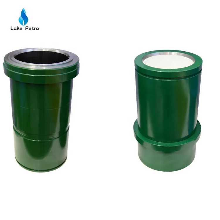
Lake Petro provides high quality Mud Pump Parts including Mud Pump Liners, Mud Pump Fluid End Module, piston, Valve and Seat etc. With more than 10 years of experience in the oil and gas industry, we are dedicated to help and support our loyal clients with the most cost-effective and quality Liners and Pistons. We also provide mud pump price and mud pump for sale.
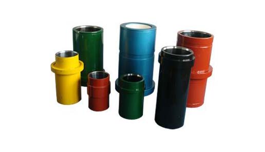
We offer Liners with Ceramic (Zirconia and Aluminium oxide) and Steel (Metal and Bi-metal) materials for all common brands of the mud pump and triplex mud pump.
Bi-metal liners (double metal liners) are made of forged steel shell and wear-resistant sleeve of high chromium iron. In the production process, the size accuracy should be strictly controlled, which can ensure that they can be easily and stably installed. The inner sleeve with high finish and hardness is wear-resistant, corrosion-resistant and has a long service life. The bi-metal liners are suitable for a lot of bad working conditions. Its service life is more than 800 hours.
Ceramic Liners are made of a ceramic inner sleeve and a forged steel outer shell. The service life of ceramic liners is about 4000 to 10000 hours, the minimum time is at least 2000 hours, which is a lot more than bi-metal liners. Because of the phase transformation toughen technology, the ceramic liners have the features of wear-resistance, erosion-resistance, high-pressure-resistance, high hardness and strength. Zirconia type and Alumina type are common type of ceramic sleeve. Compared with Alumina type, Zirconia type liners have better toughness properties and a much longer service life. Piston wear and water consumption for lubrication can be reduced as well.
Seal Rings for Liner packing are also important. Liner Seal Rings is designed and made with hard corner which is an integral part of seal rings and soft nitrile element rubber center. We could provide reliable liner Seal Rings for our customers could order them at the same time.
All Lake Petro liner products are interchangeable with O.E.M. products. Meanwhile, we provide customized Liners according to drawings. Our liners, also with our other mud pump spares, are supplied for use in Honghua, F-Series, Bomco, Emsco and National lines of triplex drilling pumps. Let Lake Petro be your one-stop shop for your whole fleet of pumps. Please refer to “Suitable Pump Models” Lable for more details.
Many things go into getting the most life out of your mud pump and its components — all important to extend the usage of this vital piece of equipment on an HDD jobsite. Some of the most important key points are covered below.
The most important thing you can do is service your pump, per the manufacturer’s requirements. We get plenty of pumps in the shop for service work that look like they have been abused for years without having basic maintenance, such as regular oil changes. You wouldn’t dream of treating your personal vehicle like that, so why would you treat your pump like that.
Check the oil daily and change the oil regularly. If you find water or drilling mud contamination in the oil, change the oil as soon as possible. Failure to do so will most likely leave you a substantial bill to rebuild the gear end, which could have been avoided if proper maintenance procedures would have been followed. Water in the oil does not allow the oil to perform correctly, which will burn up your gear end. Drilling mud in your gear end will act as a lapping compound and will wear out all of the bearing surfaces in your pump. Either way it will be costly. The main reasons for having water or drilling mud in the gear end of your pump is because your pony rod packing is failing and/or you have let your liners and pistons get severely worn. Indication of this is fluid that should be contained inside the fluid end of your pump is now moving past your piston and spraying into the cradle of the pump, which forces its way past the pony rod packing. Pony rod packing is meant to keep the oil in the gear end and the liner wash fluid out of the gear end. Even with brand new packing, you can have water or drilling fluid enter the gear end if it is sprayed with sufficient force, because a piston or liner is worn out.
Monitor your oil and keep your pistons, liners and pony rod packing in good condition. If a liner starts to leak, identify the problem and change it as soon as possible.
There is also usually a valve on the inlet of the spray bar. This valve should be closed enough so that liner wash fluid does not spray all over the top of the pump and other components.
Liner wash fluid can be comprised of different fluids, but we recommend just using clean water. In extremely cold conditions, you can use RV antifreeze. The liner wash or rod wash system is usually a closed loop type of system, consisting of a tank, a small pump and a spray bar. The pump will move fluid from the tank through the spray bar, and onto the inside of the liner to cool the liner, preventing scorching. The fluid will then collect in the bottom of the cradle of the pump and drain back down into the collection tank below the cradle and repeat the cycle. It is important to have clean fluid no matter what fluid you use. If your liners are leaking and the tank is full of drilling fluid, you will not cool the liners properly — which will just make the situation worse. There is also usually a valve on the inlet of the spray bar. This valve should be closed enough so that liner wash fluid does not spray all over the top of the pump and other components. Ensure that the water is spraying inside the liner and that any overspray is not traveling out of the pump onto the ground or onto the pony rod packing where it could be pulled into the gear end. If the fluid is spraying out of the cradle area and falling onto the ground, it won’t be long before your liner wash tank is empty. It only takes a minute without the cooling fluid being sprayed before the liners become scorched. You will then need to replace the pistons and liners, which is an avoidable costly repair. Make a point to check the liner wash fluid level several times a day.
Liner wash fluid can be comprised of different fluids, but it is recommended to just using clean water. In extremely cold conditions, you can use RV antifreeze.
Drilling fluid — whether pumping drilling mud, straight water or some combination of fluid — needs to be clean. Clean meaning free of solids. If you are recycling your fluid, make sure you are using a quality mud recycling system and check the solids content often throughout the day to make sure the system is doing its job. A quality mud system being run correctly should be able to keep your solids content down to one quarter of 1 percent or lower. When filling your mud recycling system, be sure to screen the fluid coming into the tanks. If it is a mud recycling system, simply make sure the fluid is going over the scalping shaker with screens in the shaker. If using some other type of tank, use an inline filter or some other method of filtering. Pumping out of creeks, rivers, lakes and ponds can introduce plenty of solids into your tanks if you are not filtering this fluid. When obtaining water out of a fire hydrant, there can be a lot of sand in the line, so don’t assume it’s clean and ensure it’s filtered before use.
Cavitation is a whole other detailed discussion, but all triplex pumps have a minimum amount of suction pressure that is required to run properly. Make sure this suction pressure is maintained at all times or your pump may cavitate. If you run a pump that is cavitating, it will shorten the life of all fluid end expendables and, in severe cases, can lead to gear end and fluid end destruction. If the pump is experiencing cavitation issues, the problem must be identified and corrected immediately.
The long and the short of it is to use clean drilling fluid and you will extend the life of your pumps expendables and downhole tooling, and keep up with your maintenance on the gear end of your pump. Avoid pump cavitation at all times. Taking a few minutes a day to inspect and maintain your pump can save you downtime and costly repair bills.

Internal cavities of metal objects frequently require a cladding, or a coating, that is more corrosion, oxidation and/or wear resistant than the metal object itself. This need may arise in some cases due to high temperatures created within the cavity, exposure to a corrosive or abrasive liquid, and/or to rubbing action of an internal machine member such as a piston. An example of such a metal object is the liners in mud pumps used in oil field drilling. A mud pump is a part of the oil or gas well drilling fluid circulating system, one of five major components of a rotary drilling operation. The other components are the drill string and bit, the hoisting system, the power plant and the blowout prevention system.
Drilling fluid, usually called the "mud", in most cases consists of a mixture of water, various special chemicals including corrosion inhibitors and solid particles such as Barite to increase its density. Such fluid is continuously circulated down the inside of the drill pipe, through the bottom of the bit and back up the annular space between the drill pipe and the hole. The driving force is provided by a mud pump.
A mud pump liner is basically a heavy wall pipe section with one or two retaining rings at its outer diameter. It is the wear resistance of the inner surface that determines the liner service life. Consequently, the internal surface of the liner is desirably clad with a wear resistant material. The internal cladding layer is subjected to sliding wear by the rubber piston which can wear and cause metallic structure supporting the rubber to contact the liner cladding, thus accelerating the wear process. The cladding material is also subjected to corrosion from the drilling fluid, and metal fatigue caused by cyclic loading, especially at areas where the direction of the piston motion suddenly changes, Further, micro regions of cladding may experience sudden pressurization and depressurization. These operating conditions impose stringent metallurgical requirements on the cladding materials. An ideal cladding material should, therefore, possess high hardness and high resistance to corrosion, impact and metal fatiuge. Such properties are desirably achieved by a uniform, fine grained microstructure, which has been the goal of pump liner makers of many years.
The outer, heavy wall portions of the commercially available mud pump liners typically consist of either a carbon steel, or a low alloy steel; and the liner cladding is, in most cases, a cast sleeve of iron--28% chromium alloy. The sleeve can be centrifugally cast into the steel pipe section or cast separately as a pipe, and shrink fitted into the outer pipe section, then machined to a smooth finish. These manufacturing procedures are lengthy and costly, while providing only a cast metal microstructure which is known to be chemically nonuniform, since in castings the solidification process results in natural segregation of the elemental species contained in the alloy. Furthermore, the cladding thicknesses are kept undesirably large to allow casting processes to be used. The claddings within metallic objects other than pump liners can be similarly characterized and most likely be prone to the same deficiencies.
It is a major object of the invention to provide a powder metal cladding method and apparatus for cladding the internal cavity surface of metal liners and objects, overcoming the above problem and deficiencies. In addition, the invention provides various material combinations for the production of pump liners and internally clad pipe segments for use with oilfield mud pump fluids. There are many other products that can benefit from this processing technique.
As will appear, pressurization of the grain is typically carried out by transmitting force to the grain along a primary axis, the layer extending about that axis and spaced therefrom, whereby force is transmitted by the grain away from the axis and against said layer. To this end, the method contemplates providing a die having a first chamber receiving said object, the die having a second chamber containing grain communicating with grain in the cavity, pressurizing of the grain in the cavity being carried out by pressurizing the grain in the second chamber, as for example by transmitting pressure from the grain in the second chamber to only a medial portion of the grain in the first chamber everywhere spaced from said layer. Further, the metal object is typically cylindrical, the layer being applied on an internal cylindrical surface of said object, the latter for example comprising a mud pump liner.
Referring first to FIG. 1, and alloy steel mud pump liner 10 comprises an elongated tube 11 having an outer flange 12 on one end portion. The tube axis appears at 13, and the tube inner cylindrical surface at 14. Tube 11 may be considered to represent other metal objects having interior surfaces (as at 14) facing internal cavities 15.
Referring to FIG. 2, the next step in the process is to place the liner containing the green now lightly sintered layer 11a within a step die 19 where the liner fits into the large cavity (i.e. first chamber 19) in the die as shown in the figure, and having inner cylindrical walls 19a and 19b. The die second chamber 20 throat diameter D1 should be equal to or smaller than the "green" internal diameter D2 of the mud pump liner 11a. This assures relatively shearless pressing of the green powder metal cladding 11a under largely lateral pressure during the pressurizing step. Chamber 20 has a bore 20a.
As seen in FIG. 3, pressurization takes place in a press 21 after filling both the die and the pump liner cavities with a refractory powder 22 already at a temperature near or above the consolidation temperature of the cladding powder. The pressure from ram 23 is transmitted to the liner by the horizontal forces created within the refractory powder grains. In this regard, the second chamber 20 is in axial alignment with the first chamber 19, the second chamber having a cross section less than the cross section of the first chamber, whereby pressure is transmitted from the grain 22a in the second chamber to only a medial portion of the grain 22b in the first chamber which is everywhere spaced from layer 11a. Therefore, lateral pressurizing of the grain in the cavity 19 is affected by grain pressurized longitudinally in the second chamber, and no destructive shear is transmitted to layer 11a.
The process, while remaining basically the same, may have some variations. For example, there may be an insulating material positioned between the part (the pump liner in FIG. 2) and the die to reduce heat loss before pressing.

3 pumps in the oil, gas, and water drilling industries. The process ~ is carried out by performing a number of manufacturing steps during which a worn cylinder liner is reformed and improved to produce 6 a usable liner which provides an extended period of service. I
9 IIn the oil and gas drilling rigs, these are referred to as "mud pumps" and are generally of two types: (a) a duplex pump which 11 has two reciprocating pistons which force fluid into the discharge 12 line and (b) a triplex reciprocating pump in which three pistons 13 act to force fluid into the discharge line. "Multiplex pumps"is 14 a generic term which is occasionally used to include triplex pumps ~~ and those having up to six cylinders. These fluid pumps can be 16 single acting in which fluid is discharged on alternate strokes 17 or double acting in which each stroke discharges fluid.
18 ; The fluid pumps involved in this invention are of the .1 i 19 horizontal reciprocating type in which one end is termed the l~fluid end and the other end is designated the power end. The fluid 21 end consists of a pump housing in which are fitted a number of 22 cylinders corresponding to the number of pistons which are operated 23 within the pump. The power end of the pumps contains a power 24 ~ source and connecting rods designed for supplying reciprocal driving force.
26 ` Each pump cylinder contains a liner within which the 27 piston operates over its power stroke. Other fluid end pump parts 28 are rods, valve pots, seats, gaskets and piston rubbers. The liner ~,~
2 The cylinder liner is subject ta high wear rates due to a 3 large number oE factors such as the geological formation being
4 drilled, the solids content in the fluid, the abrasive properties of the solids, and pH of the fluid, the pump pressure, strokes per 6 minute of the piston, and the materials used in the various pump 7 parts.
8 ~ The pump cylinder liner in a duplex pump typically has an 9 average life of 1200 to 1500 pump hours, that is about 90 to 100 days, andthe average life ofthe cylinder ~ners in the triplex i~ " ll;pumps is about 500 to 900 hours or about 50 to 60 days of service 12 life at a normal duty cycle. The usual maintenance practice for 13 fluid pumps is then to replace the fluid end expendable parts at 14 the end oE their respective service lives. This practice, however, has grown relatively expensive since about 50% of -the total mainten-16 ance cost is in the cylinder liners which range in price from about 17$400 to ~1~00. Thus, replacement of liners in a large sized tri-18 plex pump could run three times the larger amount. The average 19 liner costs are; however, less since these are estimated to be 20i$750 for each duplex liner and $650 for a triple~ liner.
21About 90% of the liners sold in the U.S. at the present 22 ltime are known as "premium liners" in which a alloy steel outer 23 ~hull has an inner surface layer of a wear resistant chromium 24 alloy. Such hard surfaced cylinder liners are priced in the mid to upper end of the above price range. Other "nonpremium" liners 26 are fabricated from Mild steel and have only a heat hardened inside 27 diameter, I.~., surface. The replacement of the cylinder liners 28at the end of each 50 to 100 days of the service cycle results 29 in hi~h pump maintenance costs.
30The liner replacement market in the IJ.S. and Canada is 31about 110,000 to 120,000 liners per year. Statistical maintenance _ _ . .. _ ... . _ . ~_ .... _ ._ _ _ .. .. . . . ._ .. ..... .. ,_ . . . .. . . . .. . .. . . .
~97~0 1 data has shown that the average number of liner chan~es per year 2 for a triplex pump is 7.2. At this level of use 23 liners/year 3 are required for a cost of approximately $15,000.00 while the addi-4 tional maintenance charges amount to another $15,000.00. Part of the high liner replacement cost is due to the chromium content in 6 the scrapped premium liners which is not recovered. Each of the 7 worn liners contains about 12 to 15 pounds of chromium. The wear 8 resistant chromium alloy is about 28% chromium with other elements 9 ~being magnesium, vanadium, and molybdenum~ The chromium alloy ", inner surface has a hardness of 62 to 65 on the Rockwell C scale 11 and is a wear and corrosion resistant metal surface which is heat 12 treated.
13 The premium pump cylinder liners with the chromium alloy 14 inner surfaces are manufactured by the three principal processes of (a) bi-metal centrifugal casting; (b) shrinking a wear-resistant 16 chromium iron or stainless steel alloy sleeve into the liner and 17 ,~. (c) chrome alloy platlng the inner surface of an alloy steel liner 18 hull. Other seldom used methods of producing premium liners are 19 those in which hard surface treatments are used for the steel hulls. These consist of coating the inner surface of the 21 liners with a hard metal using such techniques as plasma arc 22 spray or powdered metallurgy surfacing. These treatments produce 23 a wear-resistant layer of about 0.020 inch in thickness with an 24 additional thickness of an impregnation layer within the hull metal. The alloy steel liner hulls used for these manufacturing 26 processes are usually fabricated from 4130 to 4150 steel alloy.
~ An interesting property of the bi-metal cast and sleeve 31 liners which are both centrifugally cast is that the chromium alloy ., . _ . _ _ _ , _ _ . .. _ . . . . . . , ... . . . _ _ . .. . ....... . ... . . . .
6 The pump liner is designed to fit into the cylinder which 7 is formed in the fluid end housing of the pump and is retained 8 in the housing by a liner cage and retainer arrangement. The 9 reciprocating piston consists of a metal piston core having one or more flanged hubs and a piston rubber which is retained in 11 the gap between the flanges. The outside surface of the piston 12 rubber contacts the inner surface of the liner. Various types of 13 wear occur on the liner and the piston body. Streaking of the 14 liner bore and the piston rubbers is generally caused by aggre-gate, sand or other abrasive or foreign materials in the drilling 16 1uid. A pitted liner indicates corrosive conditions, usually 17 ~- Eound for acidity levels below 7.2. pH. A concentration of wear 18 on one side of the piston or liner can occur if various working 19 conditions such as loose cross head slides, worn pump bores, snuffing boxes and junk rings misalignment and unequal tightening 21 of the liner rod packing have occurred. Pump failure is generally 22 ,indicated by e~cessive clearance between the piston flan~e and 23 the liner wall.
24 The permissible clearance prior to replacement of the fluid end expendable parts depends upon the operating pressure. In 26 low pressure service (less than 850 psi) the total clearance may 27 be 3/32 inch or more. At medium to high pressure (850 psi to 28 1600 psi) a 1/16 inch clearance is regarded as the limit. At 29 higher operating pressures of from 1600 psi to 3200 psi a clearance of 0.04 inch is considered to indicate a "worn out" piston and/or 31 liner. At medium to high pressures the indication of normai wear a 7~1 1 in a duplex pump is between 0.06 to 0.08 inches over nominal I.D.
2 and in a triplex liner isO.G35 to 0.06 over nominal. The clearance 3 dimensionmust be taken in the center of the liner since the 4 wear occurs in the mid-portion rather than at the ends of the liners.
7 As the piston fails, there is high velocity fluid slippage 8 between the piston flange and theliner bore. With a slow failing 9 ;of the piston or if a failed piston is allowed to operate in the pump, this jetting fluid will cause wash cut damage to the piston 11 flange and liner bore and the dragging of the piston flange in the 12 bore at 180 from the wash cut. The pump efficiency and the length 13 of service life rapidly decrease with increasing piston flanges-14 to-liner clearance. For example, if the clearance is 0.040 at 3000 psi, a set of replacement rubbers can be expected to last 16 only 50 percent as ].ong as they would on a new piston in a new 17 ~ liner with a clearance of 0.010 inch.
18 The wearing of the piston and the liner can not be eliri~inated 19 due to the abrasive nature of the fluids, the corrosive properties of the same, and the high operating pressure utilized in fluid 21 pumps in the drilling industry. The required replacement of the 22 jcylinder liners results in a continual high cost of operation for 23 these fluid pumps.
24 U.S. Patent No. 2,163,885 to ~acClatchie et al describes fluid pump liners and a method of fabricating the liners in 26 which flanges are joined to cylindrical pipe sleeves. There 27 is no disclosure of removing the worn liners from the fluid pumps 28 in order to remanufacture the sameO Rather the worn liners are 29 simply replaced. This patent does not therefore describe a process for remanufacturing and thereby increasing the working life 31 of a cylinder liner.
1 U.S. Patents 2,412,587 and 2,435,837 both to Larson are 2 directed to increasing the inner diameter (I.D.) of master and 3 wheel cylinders and then inserting a tubular sleeve in order to 4 produce the original I. n. dimension. There is no disclosure in this patent of remanufacturing a removable liner for the brake 6 system cylinder.
7 It is known from U.S. Patent No. 1,842,441 to Yount to 8 rebore engine block cylinders and insert cylinder sleeves or 9 liners and to then bore the new liners to the desired size for the piston to be installed. There is no use of an extracted 11 cylinder liner in this process.
12 U.S. Patent No~ 2,686,091 to Young describes various 13 methods of making pump liners using concentric sleeves, the inner 14 one oE which is usually hardened for greater resistance to wear and for longer life. There is no mention in this patent of re-16 manufacturing the liners by reboring or grinding.
These patents do not describe remanufacturing processes wherein 26 worn pump cylinder liners are extracted from pump housing and 27 thereafter remanufactured in a manner which allows increasing 2~ of the working life of the cylinder liner.
29 It has been previously known during an earlier period when nonpremium mild steel liners were extensively used in mud pumps _ _ _ . _ . _ _ . _ _ _ .. _ _ _ . ~ . _ . , . . . _ . . .. . , .. . _ . . . ~ . , . _ . _ .. . . _ .. .
1 that the liners were sometimes removed fxom the pumps and bored 2 out to the next commercially available piston size. Such metal 3 boring and reuse of liners is not posslble and to applicant"s 4 knowledge has never been practiced with the currently used pre~lium liners because the wear-resistant metal alloy inner layer 6 in such liners is so hard that destruction of the liner and/or 7 the bore tool would occur.
8 ~, The present invention providesa process of remanufacturing 9 pump cylinder liners used in drilling fluid pumps in order to extend the working life of the liners and thus reduce operating 11 and maintenance costs. New pump liners are manufactured with bores~
5" 5.000 to 5.010 26 1~ The outer diameters of the liners are established by the 27 design of the partlcular pump and vary between the triplex and 28 duplex pump types. The liner cage and retainers also vary 29 depending upon the horse power of the pump, the length of the stroke and other design features.
1 a hard metal alloy inner layer from a pump cylinder and removing 2 portions of the interior metal surface from the liner so as to 3 form a enlarged dlameter, accurately dimensioned cylindrical surface 4 therein. An enlarged diameter,specially manufactured piston is then supplied for use in the remanufactured liner. Prior to
12 The metal removing step is carried out by honing or by 13 internally grinding the liner to produce an enlarged cylindrical 14 interior surface. Honing is preferred since grinding has been found to require longer preparation time for the wear-resistant 16 hard metal inner surface layer of the liners. Prior to and during 17 -~ the metal removing step the liner axis is aligned with and clamped 18 with respect to a honing or grinding apparatus. The amount of 19 metal removed is sufficient to eliminate the center-to-end wear curvature in the liner. It is preferred to remove sufficient 21 material so that the enlarged diameter is 0.100 inch over the 22 original nominal size of the liner as employed in the fluid pump 23 prior to the extraction of the liner.
24 The remanufactured liner is then supplied for use in a fluid pump with a specially sized piston. The removal of only 26 OolO0 inch from the I.~. permits multiple remanufacturing cycles 27 in order to extend the working life of the same liner in accordance 28 with the invention hereof. Two or more such multiple remanufactur-29 ing cycles can be safely carried out on the pump cylinder liners dicclosed herein. In the cases of the chrome plated and the hard 1 coating treated liners intermediate plating and coating steps are 2 performed during the successive remanufacturing cycles. The 3 liners manufactured with shrunk-in sleeves and by bi~metal 4 casting are preferably remanufactured according to the present invention by successive metal removal cycles.
6 The present remanufacturing process for producing pump 7 cylinder liners reduces drilling fluid pump maintenance costs 8 to about 75% of the costs when the liners are only replaced 9 when worn to the limit of usefulness~ This amounts to a savings of about $250 to $300 per liner reinstalled. The process saves 11 scarce chromium all of which is imported into the U.S. and saves 12 the energy expended in the original manufacture of new liners 13 from the ore reduction through the va~ious finishing steps.
14 The remanufacturing process uses as one of its input factors a worn liner which is often in the correct general form 16 but which is regarded as a disposable fluid end component in the . ~
18 It is therefore an object of the present invention to 19 provide a process of remanufacturing and thus increasing the working life of a cylinder liner which is then positioned for 21 use in a drilling fluid pump.
22 ~nother object of the present invention is to provide a 23 process of remanufacturing a worn pump cylinder liner in which 24 the internal, worn portions are eliminated by the removal of about 0.100 inch of metal based on the nominal diameter size of the 26 liner prior to the wearing action.
27 Yet another object of the present invention is to provide 28 a process as above described wherein the extent of wear in the 29 liner can be checked prior to extracting the liner from the pump _g_ ~ "~
`" ~LZ~97 l and wherein the surface condition of the liner can be evaluated 2 prior to the removal of worn portions of metal from the interior 3 surface in order to form an enlarged diameter interior surface.
4 Another object is to provide a process of refitting a drilling fluid pump with a remanufactured liner in which a worn 6 pump liner is extracted from a pump cylinder and the I.D. enlarged 7 to eliminate the worn areas.
8 Yet another object is to provide a process for making 9 an improved pump liner wherein wear-resistant surface metal is removed fro~ the I.D. of a worn liner to uncover and present a ll more dense and hence more wear-resistant metal surface for contact 12 by the pump piston.
22 Figure 3 shows a cut-away cross-sectional view of a worn 23 pump liner i~w}1ici1the hard ~etal inner layer hasbeen accentuated;and 24 Figure ~ shows the worn pump liner of Figure 3 aligned with a honing apparatus for removal of metal from the interior surface 26 in order to form an enlarged diameter cylindrical surface therein.
1 acting duplex pump 10 which consists of a fluid end pump housing 2 12 having a first cylinder 14 and a second cylinder 16 formed there-3 in. Each of the cylinders contains a cylinder liner 18 and 20, 4 respectively. The cylinder liners are retained by cages 22 and 24 respectively which engage retaining rings 26 and 28.
6 Pistons 30 and 32 are reciprocated by piston rods 34 and 7 36 through power delivered from the power end 38. In operation, 8 the pistons reciprocate within the inner surfaces of the cylinder 9 liners 18 and 20 and thus cause theliners to wear. The wear is not uniformly distributed across the entire length of the 11 inner diameter surface but rather is concentrated in the mid-12 portion of the liner as will be hereinafter further detailed. In 13 the double-acting pump illustrated, fluid suction valve pots 14 40 and 44 and discharge valve pots 42 and 46 are located at respect-ive ends of each cylinder liner 20. In this construction each 16 stroke of the piston 32 causes fluid to exit from either of the 17 -~ valve pots 42 or 46. In the position shown, the next stroke of 18 the piston will cause fluid to flow through the discharge pot:
27 Piston 30 operates in the same manner as previously des-28 cribed with respect to piston 32. An intake line 52 is shown 29 mounted in the bottom portion of the pump housing 12 for communi-cation with the suction valve pots 40, 44, 48 and 50.
1 The two cylinders 14 and 16 are constructed with cylinder 2 heads 54 and 56, r~spectively, which removably retain cylinder 3 head covers 58 and 60 as well as the liner cages 22 and 24. A
6 Liner packings 70 and 72 in the form of ring packing glands are 7 provided between the cages 22 and 24 and the retaining rings 8 26 and 28. The reciprocating rods 34 and 36 move through stuffing 9 boxes 74 and 76 which are suitably equipped with junk rings, packing and gland nut fittings.
19 According to the process of the present invention, the condition o~ wear on the interior surfaces of liners 18 and 20 21 is inspected by first interrupting the power supply 38 and then 22 withdrawing the pistons 30 and 32 toward the power end 38. The 23 cylinder heads 54 and 56, the cylinder head covers 58 and 60, 24 and the liner cages 22 and 24 are also removed in order to insert a measuring micrometer into the liner while it is still retained 26 in the pump housing 12. Accurate measurement of the. extent of 27 wear and inspection for wear grooves, streaking of the liner bore 28 and washed cut damage can be carried out in this manner at a low 29 service cost level.
4 2. The procured liners are cleaned on both of the inner and outer surfaces by one or a combination of (a) 6 shot blasting with pellets, (b) sand blasting, and/or 7 - (c) cleaning with a solvent.
8 3. The inside diameter of the liners is then evaluated g to determine whether or not a sufficient thickness l of the hard surface alloy metal exists to permit 11 enlargement of the I.D. during the formation of 12 a reformed cylindrical inner surface.
13 ~ 4. The extent of wear on the outer surface of the liners 14 18 and 20 is inspected to determine whether or not the degree of wear in the packing areas, flanges, 16 ` or ends of the liner will interfer with the sub-17 sequent steps in the remanufacturing method.
18 5. If the outer surfaces are sufficiently worn or out of 19 dimensional specification, these surfaces can be built up with weld, spray metal, or cold metal applications 21 while internally cooling the liner which has an 22 intact inner hard metal alloy sleeve. The liner is 23 subsequently machined to reproduce the manufacturer"s 24 external liner specifications prior to enlarging the inner diameter. An engine lathe or a turret lathe 26 can be used for this machining step. In this machin-27 ing, internal chuck jaws can be employed for holding 28 the liners since these liners will be chucked on the 29 outer end portions of the I.D. where no piston wear .. ... .... .. . ..
1 has occurred. In this manner, any build-up of 2 metal and subsequent machining will be concentric 3 with the original bore and the O.D. of the liner.
4 6. Prior to and during the removal of metal from the S outer or the inner surface the liner axis is aligned 6 with the working a~is o~ a surface metal removal 7 device.
8 ~ 7. Portions of the interior hard metal surface layer 9 ~ are then removed to form an accurately dimensioned c~lindrical I.D. surface. This step is carried out 11 by honing and/or internal grinding in which the 12 liner is centered and held or clamped on the honing 13 ~ or grindin~ machine by adapter flanges which are 14 E)ressed against the two ends of the liner. The centering is carried out by aliyning the axes of 16 the liner ~nd the metal removal head of the machine.
17 ` ~letal is removed on the I.D. of the liner in order 18 to obtain an I.D. of +0.100 inch over the nominal 19 size of the original liner, that is, +0.050 inch is removed from the cylindrical wall surface.
21 If this increase in I~D. is insufficient to clean 22 out any wear grooves and the central wear zone in the 23 liner, additional material can be removed. This 24 step is carried out by good machining practices to obtain a ma~imum of 16 rms finish.
26 8. In this process, the American Petroleum Institute 27 (API) specifications permit a 0.010 inch tolerance 28 on the I.D. of the liner and the piston. Hence, 29 after the liner is honed or grounded to the enlarged size it is rechecked to ma~e sure the I.D. is within ~.
9. The liner is then painted, crated, and supplied with the proper sized piston so that a nominal sized piston matching the original liner will not be used by mistake.
Enlarged diameter pistons to fit the remanufac-tured liners can be produced by known manufacturing pro-cesses. These pistons will be sized from +0.100 to +0.110 inch over the nominal size pistons. These specially sized pistons can be packed with the remanufactured liner. The removal of only +0.100 inch of material from the inner surface allows multiple remanufacturing cycles with the same liner as above stated.
Of this preferred process, steps 1 and 7 are required, in principal, -to effect remanufacturing and sub-sequent use of the liner. The remaining steps are desirable according to the field practice.
4 It is not possible to use broaching or boring for removing metal from the I.D. of the liners since the wear-resistant 6 metal inner layers are too hard. It has been found that broaching 7 and/or boring will crack the bi-metal or cast sleeves of hard metal 8 alloyand can cause unacceptable heat build-up and thus loss of g the hardening temper of the metal alloy surface, or that the tools break., 11 Referring now to Figure 2 a pump 110 of an "L" head design .2 is shown constructed of a pump housing 112 having an intake or 13 suction valve pot 114 and an outlet or discharge valve pot 116 14 arranged therein together with a fluid cylinder 118, a retainer 1S sleeve 120 and a liner retention arrangement 122 which holds 16 liner 124 in an operative position within pump housina 112. A
17 piston 125 having a hub 126 and a rubber 127 is moved by piston 18 rod 128 reciprocally within the interior of liner 124 by 19 a power source 130. A fluid intake line 132 is located in fluid communication with outlet valve pot 116. The construction of the 21 valve covers 136 and 138, valve seats 140 and 142, valve spring 22 144 and 146 and of the piston 126 are similar to those elements 23 described with respect to Figure 1.
24 Fluid pump 110 is single acting inthatfluid is drawn in through valve pot 114 on the stroke of the piston to the left hand 26 side as illustrated and then fluid is ejected from the pump as the 27 piston moves to the right hand side. The liner 124 can be in-28 spected for the wear conditions by removal of piston 126 towards 29 the power source 130 and unhitching the coupling 148. The liner is then remanufactured according to the above described steps.
31 Figure 3 shows~a cu-t-away view of a typically worn liner .. . .. . . . , .. , . _ ,, . . . . . . ~
1 recessed flange adapters 192 and 194. Force is applied on the 2 adaptersin the direction of the arrows A and B in order to hGld 3 the liner in a secured and centered position with respect to 4 honing head 180. The adapters 192 and 194 thus function as center-ing and holding means for the liner.
6 The honing apparatus 170 is designed to make multiple 7 axial passes on the liner 150 in order to remove metal to produce 8 the enlar~ed diameter inner surface therein~ As illustrated this g can be carried out by a vertically reciprocating and rotating honing head. The time required for the multiple honing passes 11 is typically 30 to 120 minutes depending upon the wear condition 12 of the worn liner.
found in the end portions, 158 and 160 in a duplex liner. The 16 correspondillg wear dimension in a triplex liner is 0.05 to 0.060 17 inch. Thls wear ~ap is then eliminated by removing metal from the 18 inner surface sufficient to produce a 0.100 inch over nominal 19 I.D. as stated above in the metal removing step illustrated in Figure 4.
21 As stated above, the alloy composition near the wear-22 ~resistant layer and hull interface of bi-metal and sleeve cast 23 liners denoted by parting line 196 in Figure 4 is more dense 24 and is closer to the theoretical specification of the alloy composition than is the bulk of the wear-resistant layer 154 which 26 is removed by the honing apparatus. This results in the remanu-27 factured liner having better wear-resistant properties than the 28 original liner prior to use in the pump. Thus the present invention 29 permits the fabrication of an improved liner by forming an inner surface of more wear-resistant metal.
1 The length of the liners illustrated by Figures 3 and 4 2 ranges from 12 inches to 28 inches and the I.D. range is from 3 3 inches to 8 inches.
4 The pump liners having chrome plated inner surface which account for about five percent of the unit volume in the liner 6 market are preferrably remanufactured in a slightly different 7 manner. The used liner, once extracted from the pump cylinder 8 is honed out to enlarge the diameter to 0.140 inch over the 9 nominal size and replated to add on a 0.02 inch layer of new plate. Then the enlarged diameter, replated liner is honed to 11 accurate dimension by removing 0.002 to 0.003 inch of metal.

For the successful execution of your projects, it is important to find an appropriate company with a good track record. We help you in connecting with the top mud pump manufacturers and companies and get the best quotation.
The most widely used mud pumps across the industry are Triplex Reciprocating Pumps. Their application has gained immense popularity with time because they are 30% lighter than duplex reciprocating pumps with relatively less operational cost. Moreover, through these pumps the discharge of mud is smooth and they are capable of moving large volume of mud at higher pressure.
Yes. We help you find the best mud pumps irrespective of your location. We simplify your search by connecting you with top mud pump manufacturers and mud pump companies in your location, according to your budget and business requirement.
The most widely used mud pumps across the industry are Triplex Reciprocating Pumps. Their application has gained immense popularity with time because they are 30% lighter than duplex reciprocating pumps with relatively less operational cost. Moreover, through these pumps the discharge of mud is smooth and they are capable of moving large volume of mud at higher pressure.
The different parts of a mud pump are Housing itself, Liner with packing, Cover plus packing, Piston and piston rod, Suction valve and discharge valve with their seats, Stuffing box (only in double-acting pumps), Gland (only in double-acting pumps), and Pulsation dampener. A mud pump also includes mud pump liner, mud pump piston, modules, hydraulic seat pullers along with other parts.
The wearing parts of a mud pump should be checked frequently for repairing needs or replacement. The wearing parts include pump casing, bearings, impeller, piston, liner, etc. Advanced anti-wear measures should be taken up to enhance the service life of the wearing parts. This can effectively bring down the project costs and improve production efficiency.
FET manufactures a full range of valves and seats for every drilling and well-servicing application as part of our full line of Osprey® mud pump system solutions. All of our valves and seats can be used in water, water base, oil base and synthetic base mud applications. FET offers additional valves and seats not listed below, including drilling valves, frac valves and well service valves. FET’s QC standards for the dimensional and material specs are extremely rigid in comparison to other manufacturers. Contact your FET representative to learn more.

Drilling consumables such as mud pump systems and their components can drastically increase your uptime while reducing costs and health/safety/environmental (HSE) risks. To support your drilling needs, Forum’s patented P-Quip® mud pump system offers a single-source solution that integrates high-quality fluid end components for maximum longevity and performance.
With more than 20 years of successful operation in severe environments, P-Quip offers a proven track record for the lowest cost of ownership in the industry. As part of our commitment to quality, our mud pump parts use patented Banded Bore™ technology that significantly reduces stress concentrations and leads to longer module life.

A mud pump (sometimes referred to as a mud drilling pump or drilling mud pump), is a reciprocating piston/plunger pump designed to circulate drilling fluid under high pressure (up to 7,500 psi or 52,000 kPa) down the drill string and back up the annulus. A mud pump is an important part of the equipment used for oil well drilling.
Mud pumps can be divided into single-acting pump and double-acting pump according to the completion times of the suction and drainage acting in one cycle of the piston"s reciprocating motion.
Mud pumps come in a variety of sizes and configurations but for the typical petroleum drilling rig, the triplex (three piston/plunger) mud pump is used. Duplex mud pumps (two piston/plungers) have generally been replaced by the triplex pump, but are still common in developing countries. Two later developments are the hex pump with six vertical pistons/plungers, and various quintuplexes with five horizontal piston/plungers. The advantages that these new pumps have over convention triplex pumps is a lower mud noise which assists with better measurement while drilling (MWD) and logging while drilling (LWD) decoding.
The fluid end produces the pumping process with valves, pistons, and liners. Because these components are high-wear items, modern pumps are designed to allow quick replacement of these parts.
To reduce severe vibration caused by the pumping process, these pumps incorporate both a suction and discharge pulsation dampener. These are connected to the inlet and outlet of the fluid end.
The pressure of the pump depends on the depth of the drilling hole, the resistance of flushing fluid (drilling fluid) through the channel, as well as the nature of the conveying drilling fluid. The deeper the drilling hole and the greater the pipeline resistance, the higher the pressure needed.
With the changes of drilling hole diameter and depth, the displacement of the pump can be adjusted accordingly. In the mud pump mechanism, the gearbox or hydraulic motor is equipped to adjust its speed and displacement. In order to accurately measure the changes in pressure and displacement, a flow meter and pressure gauge are installed in the mud pump.
The construction department should have a special maintenance worker that is responsible for the maintenance and repair of the machine. Mud pumps and other mechanical equipment should be inspected and maintained on a scheduled and timely basis to find and address problems ahead of time, in order to avoid unscheduled shutdown. The worker should attend to the size of the sediment particles; if large particles are found, the mud pump parts should be checked frequently for wear, to see if they need to be repaired or replaced. The wearing parts for mud pumps include pump casing, bearings, impeller, piston, liner, etc. Advanced anti-wear measures should be adopted to increase the service life of the wearing parts, which can reduce the investment cost of the project, and improve production efficiency. At the same time, wearing parts and other mud pump parts should be repaired rather than replaced when possible.

abstractNote = {Failure of a liner seal is one of the more critical failures on a mud pump because this seal interfaces with the pump body. Therefore, failures, usually damage the pump body, leading to repair or replacement of the fluid end itself. One of the more common liner seal problems involves counter-bore-type seals. This type of seal is easily affected by two aspects of the problem that are found in the mud pump fluid end-wear and foreign matter in the seal groove. Factors relative to difficult liner removal are discussed. Piston damage, careless seal installation and corrosion damage are also examined.},


 8613371530291