
mud pump liner handling tool free sample
The 2,200-hp mud pump for offshore applications is a single-acting reciprocating triplex mud pump designed for high fluid flow rates, even at low operating speeds, and with a long stroke design. These features reduce the number of load reversals in critical components and increase the life of fluid end parts.
The pump’s critical components are strategically placed to make maintenance and inspection far easier and safer. The two-piece, quick-release piston rod lets you remove the piston without disturbing the liner, minimizing downtime when you’re replacing fluid parts.

Internal cavities of metal objects frequently require a cladding, or a coating, that is more corrosion, oxidation and/or wear resistant than the metal object itself. This need may arise in some cases due to high temperatures created within the cavity, exposure to a corrosive or abrasive liquid, and/or to rubbing action of an internal machine member such as a piston. An example of such a metal object is the liners in mud pumps used in oil field drilling. A mud pump is a part of the oil or gas well drilling fluid circulating system, one of five major components of a rotary drilling operation. The other components are the drill string and bit, the hoisting system, the power plant and the blowout prevention system.
Drilling fluid, usually called the "mud", in most cases consists of a mixture of water, various special chemicals including corrosion inhibitors and solid particles such as Barite to increase its density. Such fluid is continuously circulated down the inside of the drill pipe, through the bottom of the bit and back up the annular space between the drill pipe and the hole. The driving force is provided by a mud pump.
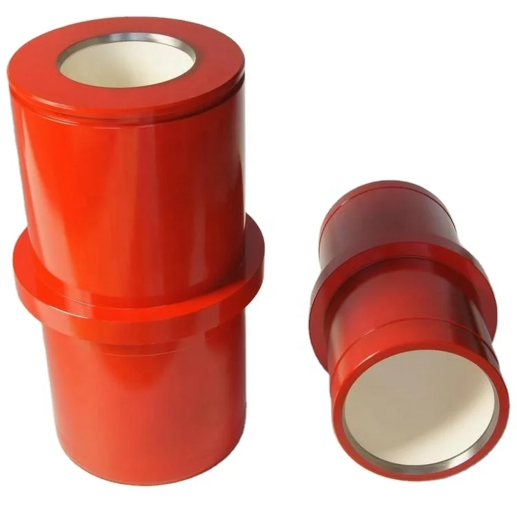
A mud pump liner is basically a heavy wall pipe section with one or two retaining rings at its outer diameter. It is the wear resistance of the inner surface that determines the liner service life. Consequently, the internal surface of the liner is desirably clad with a wear resistant material. The internal cladding layer is subjected to sliding wear by the rubber piston which can wear and cause metallic structure supporting the rubber to contact the liner cladding, thus accelerating the wear process. The cladding material is also subjected to corrosion from the drilling fluid, and metal fatigue caused by cyclic loading, especially at areas where the direction of the piston motion suddenly changes, Further, micro regions of cladding may experience sudden pressurization and depressurization. These operating conditions impose stringent metallurgical requirements on the cladding materials. An ideal cladding material should, therefore, possess high hardness and high resistance to corrosion, impact and metal fatiuge. Such properties are desirably achieved by a uniform, fine grained microstructure, which has been the goal of pump liner makers of many years.
The outer, heavy wall portions of the commercially available mud pump liners typically consist of either a carbon steel, or a low alloy steel; and the liner cladding is, in most cases, a cast sleeve of iron--28% chromium alloy. The sleeve can be centrifugally cast into the steel pipe section or cast separately as a pipe, and shrink fitted into the outer pipe section, then machined to a smooth finish. These manufacturing procedures are lengthy and costly, while providing only a cast metal microstructure which is known to be chemically nonuniform, since in castings the solidification process results in natural segregation of the elemental species contained in the alloy. Furthermore, the cladding thicknesses are kept undesirably large to allow casting processes to be used. The claddings within metallic objects other than pump liners can be similarly characterized and most likely be prone to the same deficiencies.
It is a major object of the invention to provide a powder metal cladding method and apparatus for cladding the internal cavity surface of metal liners and objects, overcoming the above problem and deficiencies. In addition, the invention provides various material combinations for the production of pump liners and internally clad pipe segments for use with oilfield mud pump fluids. There are many other products that can benefit from this processing technique.
As will appear, pressurization of the grain is typically carried out by transmitting force to the grain along a primary axis, the layer extending about that axis and spaced therefrom, whereby force is transmitted by the grain away from the axis and against said layer. To this end, the method contemplates providing a die having a first chamber receiving said object, the die having a second chamber containing grain communicating with grain in the cavity, pressurizing of the grain in the cavity being carried out by pressurizing the grain in the second chamber, as for example by transmitting pressure from the grain in the second chamber to only a medial portion of the grain in the first chamber everywhere spaced from said layer. Further, the metal object is typically cylindrical, the layer being applied on an internal cylindrical surface of said object, the latter for example comprising a mud pump liner.
Referring first to FIG. 1, and alloy steel mud pump liner 10 comprises an elongated tube 11 having an outer flange 12 on one end portion. The tube axis appears at 13, and the tube inner cylindrical surface at 14. Tube 11 may be considered to represent other metal objects having interior surfaces (as at 14) facing internal cavities 15.
Referring to FIG. 2, the next step in the process is to place the liner containing the green now lightly sintered layer 11a within a step die 19 where the liner fits into the large cavity (i.e. first chamber 19) in the die as shown in the figure, and having inner cylindrical walls 19a and 19b. The die second chamber 20 throat diameter D1 should be equal to or smaller than the "green" internal diameter D2 of the mud pump liner 11a. This assures relatively shearless pressing of the green powder metal cladding 11a under largely lateral pressure during the pressurizing step. Chamber 20 has a bore 20a.
As seen in FIG. 3, pressurization takes place in a press 21 after filling both the die and the pump liner cavities with a refractory powder 22 already at a temperature near or above the consolidation temperature of the cladding powder. The pressure from ram 23 is transmitted to the liner by the horizontal forces created within the refractory powder grains. In this regard, the second chamber 20 is in axial alignment with the first chamber 19, the second chamber having a cross section less than the cross section of the first chamber, whereby pressure is transmitted from the grain 22a in the second chamber to only a medial portion of the grain 22b in the first chamber which is everywhere spaced from layer 11a. Therefore, lateral pressurizing of the grain in the cavity 19 is affected by grain pressurized longitudinally in the second chamber, and no destructive shear is transmitted to layer 11a.
The process, while remaining basically the same, may have some variations. For example, there may be an insulating material positioned between the part (the pump liner in FIG. 2) and the die to reduce heat loss before pressing.

Heating, Ventilation and Air Conditioning Landlord shall furnish to the Premises heating, ventilation and air-conditioning (“HVAC”) in accordance with the Design Standards set forth in Exhibit D during Ordinary Business Hours. Landlord shall have access to all air-cooling, fan, ventilating and machine rooms and electrical closets and all other mechanical installations of Landlord (collectively, “Mechanical Installations”), and Tenant shall not construct partitions or other obstructions which may interfere with Landlord’s access thereto or the moving of Landlord’s equipment to and from the Mechanical Installations. No Tenant Party shall at any time enter the Mechanical Installations or tamper with, adjust, or otherwise affect such Mechanical Installations. Landlord shall not be responsible if the HVAC System fails to provide cooled or heated air, as the case may be, to the Premises in accordance with the Design Standards by reason of (i) any equipment installed by, for or on behalf of Tenant, which has an electrical load in excess of the average electrical load and human occupancy factors for the HVAC System as designed, or (ii) any rearrangement of partitioning or other Alterations made or performed by, for or on behalf of Tenant. Tenant shall install, if missing, blinds or shades on all windows, which blinds and shades shall be subject to Landlord’s approval, and shall keep operable windows in the Premises closed, and lower the blinds when necessary because of the sun’s position, whenever the HVAC System is in operation or as and when required by any Requirement. Tenant shall cooperate with Landlord and shall abide by the rules and regulations which Landlord may reasonably prescribe for the proper functioning and protection of the HVAC System. Tenant acknowledges that the server room in the Premises currently has three heat pumps installed, being two 4-ton units, and one 2.5-ton unit (the “Existing Heat Pumps”). The 2.5-ton unit is currently connected and operational. Tenant shall determine whether it is satisfied with the condition of the Existing Heat Pumps and Landlord shall not have any responsibility or liability for the condition, operation, maintenance, repair or replacement of the Existing Heat Pumps. Tenant may operate the Existing Heat Pumps. Tenant shall be responsible for, and pay directly for, all necessary maintenance and repairs to the Existing Heat Pumps. Tenant shall reimburse Landlord monthly for the cost of all utility services used to operate the Existing Heat Pumps within 10 Business Days after receipt of Landlord’s invoice for such amount. Landlord may measure Tenant’s usage of such utility services by either a sub-meter or by other reasonable methods such as by temporary check meters or by survey. Tenant, at its cost, may replace the Existing Heat Pumps with one or more new heat pumps, provided, however, that the capacity of such replacement heat pump(s) shall not exceed the 10.5-ton capacity cooling capacity of the Existing Heat Pumps.
Rubric The rubrics are a scoring tool used for the Educator’s self-assessment, the formative assessment, the formative evaluation and the summative evaluation. The districts may use either the rubrics provided by ESE or comparably rigorous and comprehensive rubrics developed or adopted by the district and reviewed by ESE.

Lake Petro provides high quality Mud Pump Parts including Mud Pump Liners, Mud Pump Fluid End Module, piston, Valve and Seat etc. With more than 10 years of experience in the oil and gas industry, we are dedicated to help and support our loyal clients with the most cost-effective and quality Liners and Pistons. We also provide mud pump price and mud pump for sale.
We offer Liners with Ceramic (Zirconia and Aluminium oxide) and Steel (Metal and Bi-metal) materials for all common brands of the mud pump and triplex mud pump.
Bi-metal liners (double metal liners) are made of forged steel shell and wear-resistant sleeve of high chromium iron. In the production process, the size accuracy should be strictly controlled, which can ensure that they can be easily and stably installed. The inner sleeve with high finish and hardness is wear-resistant, corrosion-resistant and has a long service life. The bi-metal liners are suitable for a lot of bad working conditions. Its service life is more than 800 hours.
Ceramic Liners are made of a ceramic inner sleeve and a forged steel outer shell. The service life of ceramic liners is about 4000 to 10000 hours, the minimum time is at least 2000 hours, which is a lot more than bi-metal liners. Because of the phase transformation toughen technology, the ceramic liners have the features of wear-resistance, erosion-resistance, high-pressure-resistance, high hardness and strength. Zirconia type and Alumina type are common type of ceramic sleeve. Compared with Alumina type, Zirconia type liners have better toughness properties and a much longer service life. Piston wear and water consumption for lubrication can be reduced as well.
Seal Rings for Liner packing are also important. Liner Seal Rings is designed and made with hard corner which is an integral part of seal rings and soft nitrile element rubber center. We could provide reliable liner Seal Rings for our customers could order them at the same time.
All Lake Petro liner products are interchangeable with O.E.M. products. Meanwhile, we provide customized Liners according to drawings. Our liners, also with our other mud pump spares, are supplied for use in Honghua, F-Series, Bomco, Emsco and National lines of triplex drilling pumps. Let Lake Petro be your one-stop shop for your whole fleet of pumps. Please refer to “Suitable Pump Models” Lable for more details.

The RIG will be mobilized from XXX to XXX. The rig will be moored in approximately xxx’ water depth. A string of 36” x 1.5” and 1.0" wall structure pipe will be jetted to xxx’ TVD / MD (xxx’ BML). The shallow hazards survey indicates possible low risk shallow gas potential from the mudline to approx. xxx’ TVD (xxx’ BML) and negligible to moderate risk shallow water flow potential at xxx’ TVD / MD (xxx’ BML).
After jetting the 36” structure pipe to the desired depth, the Drill Ahead Tool (DAT) will be used to drill 26” hole to xxx’ TVD / MD (xxx’ BML) and 20” casing will be run and cemented. The shallow water flow study indicates only low to moderate potential for over-pressured sands through this interval. Should a shallow flow be encountered while drilling riserless, 16.0 ppg kill mud will be available on the rig to control any such flow. After running and cementing 20” casing, the subsea BOP stack and riser will be run and tested. Prior to drilling out of the 20” casing, the hole will be displaced with 10.0 ppg synthetic based mud. A LOT of 10.7 ppg is expected at the 20” casing shoe. LWD (GR/RES/APWD/DIR) will be utilized in this hole section.
A 17’’ x 20” hole will be drilled to xxx’ TVD / MD and 16” casing will be run and cemented. This casing string is being set at this depth based on pore pressure and frac gradient. The expected mud weight at casing point is 10.4 ppg and the expected LOT at the 16” casing shoe is 12.4 ppg EMW. LWD (GR/RES/APWD/DIR) will be utilized in this hole section.
A 14 1/2’’ x 17 1/2” hole will be drilled to xxx’ TVD / xxx’ MD. The KOP for the directional work is planned at 7300" TVD/MD. A major azimuth change while building hole angle will be accomplished in this section using rotary steerable tools. A full string of 13 5/8” casing will be set. The expected mud weight at casing point is 12.0 ppg and the expected LOT at the 13 5/8” casing shoe is 14.2 ppg EMW. LWD (GR/RES/APWD/DIR) will be utilized in this hole section.
A 12 1/4’’ x 15" directional hole will then be drilled utilizing rotary steerable tools and LWD (GR/RES/APWD/DEN/NEUT/DIR) to xxx" TVD / xxx" MD. The 1st target zone will be encountered in this hole section at xxx" TVD. A wireline logging program consisting of GR/Dipole Sonic, RCI, and SWC will be run in this hole section. An 9 7/8" liner will be set in this hole section. The expected mud weight at casing point is 13.0 ppg and the expected LOT at the 11 7/8” casing shoe is 14.9 ppg EMW.
A 9 7/8’’ x 12 1/4" directional hole will then be drilled utilizing rotary steerable tools and LWD (GR/RES/APWD/DEN/NEUT/DIR) to xxx" TVD / xxx" MD. The primary target zones will be encountered in this hole section at xxx" TVD and xxx" TVD. A wireline logging program consisting of GR/Dipole Sonic, RCI, and SWC will be run in this hole section. A 9 7/8" liner will be set in this hole section. The expected mud weight at casing point is 14.4 ppg and the expected LOT at the 9 7/8” casing shoe is 15.8 ppg EMW.
An 8-1/2’’ hole will then be drilled to TD at xxx’ TVD / xxx’ MD utilizing rotary steerable tools and LWD (GR/RES/APWD/DEN/NEUT/DIR). The lower target zones will be encountered in this hole section at 14110" TVD and 14506" TVD. A wireline logging program consisting of GR/Dipole Sonic, RCI, SWC, MRILL, Earth Imager, and Check Shot will be run in this hole section. The expected mud weight at TD is
As the rig approaches the actual location, the AHV will begin placement of the 1st anchor. XXX will provide tools, equipment, crews for anchor handling operations, and contingency equipment.
P/U and stand back drill pipe and inner jetting assembly with a rock 26" bit. P/U CADA (Cam-Actuated Drill Ahead) running tool, M/U on wellhead housing and stand back.
Run required joints to allow 280" of penetration BML with 12" of stick up with the gas/mud mat at the ML. Make up connection and torque to recommended optimum torque. (See detailed VETCO procedure in the specific casing program section) Clean threads and apply API modified casing dope.
Make up CADA on inner jetting assembly and land in wellhead housing. Confirm the tool is locked in the housing and the ports in the top of the tool are open.
Pick up the entire structural casing string and wellhead assembly and note the weight. Lower the casing assembly on the landing string until the shoe is located 10" above the mud line as follows:
Start pump at 200 gpm to keep bit nozzles from plugging when tagging mud line. Record string weight. Tag mud line and record depth. Record bull’s-eye angle and direction.
Record the following data on a basis: Time to jet 5", WOB, gpm, psi, comments, and notations on pipe reciprocation (when and how much the pipe was reciprocated) and the pumping of sweeps (volume and viscosity). Also note any overpull while working pipe.
Pump 50 bbl (or slugging pit volume) hi-vis (FV > 100 sec) sweeps of seawater and prehydrated bentonite at each connection (more frequently if needed) and 50 bbl (or slugging pit volume) hi-vis pill at each half stand drilled.
Make a wiper trip to the structural casing shoe with seawater in the hole. Circulate hole clean and displace 150% hole volume with 13.5 ppg CaCl2 spotting mud. To prevent potential wellbore instability, DO NOT place freshwater mud in the hole.
Utilize the blender to increase the mud weight from 12.0 to 14.0 ppg and circulate a minimum of two hole volumes. Circulate at max. rate during kill. Monitor ECD with the APWD readout.
Shut down pumping and monitor well for flow with ROV. If well is still flowing, continue mud weight increase to kill the flow. Once well is dead, options will be discussed with members of the extended drilling team.
If a water flow is encountered, attempt to determine relative severity of flow. If water flow is minimal, consideration will be made to continue drilling to the 20” casing point. If flow is severe, increasing the mud weight or a dynamic kill will be considered. In either case, contact the COMPANY drilling staff to discuss options.
Collapse Caution: It is imperative that the casing string and drill pipe running string be full of fluid while running. Once the 20” shoe has entered the 36” Low Pressure Wellhead Housing, pump at least 1-1/2 casing volumes to assure that the strings are full.
Pick up the 5 1/2" 38 ppf landing string and RIH. Lower the wellhead to the water and pump out all the air from the 20" x inner string annulus. Close the both vent valves on top of the running tool (vent valves should have double valves for redundancy).
Continue running the casing on drill pipe to the mud line, filling the drill pipe every 5 stands. See Figure No. 2 at the end of this section for running weights and tensile capacities.
Wash with weighted mud if needed due to hole conditions. Do not "routinely" wash casing to bottom (avoid displacing the 13.5 ppg mud whenever possible).
Adjust the heave compensator to support about 2,000–3,000 lbs more than running string, WHRT, and cementing stinger weight. Release WHRT per VETCO operations manual and on-site VETCO service technician. When the tool releases, the heave compensator will stroke closed lifting the tool free from the housing.
Hold pre-job safety meeting on handling and running procedures for BOP stack, LMRP, and marine riser with all parties involved. Adhere to weather limitations as per rig-specific operations manual supplement.
a) Install the methanol / glycol injection umbilical for the H-4 connector ROV quick stab. Stab umbilical into ROV port. Colored methanol / glycol will be pumped through the umbilical to flush connector cavity at ±7 day intervals. Glycol is preferable.
a) Record hook load every joint while running riser. Also record weights for the TDS/Traveling Block, riser running tool, tensioning ring (if not integral to telescopic joint), and diverter housing/upper flex joint. Send data to Drilling Engineer for review.
The well design with multiple liners provides several areas in which cuttings beds will accumulate. It is advisable to clean these areas during each trip out of the hole.
20" - 25" for rat hole is sufficient below long strings of casing, and 5" is sufficient below the liners. This limits the length of oversized, open hole below casing shoes where cuttings can accumulate. It also prevents excessive cement slump that can detrimentally effect the shoe test upon drilling out that can be a problem given the recommended cement slurry densities vs. the planned section TD MWs.
When pumping a sweep pull the bit off bottom prior to the sweep exiting the bit. Ensure the drill string is at least 60 RPM while the sweep exits the bit. Increase the drill string rotation to a minimum of 120 RPM while pumping the maximum GPM while the sweep is moving up the annulus. Consider pumping piggyback sweeps by using a low vis then high vis sweep.
Always CBU with a maximum pump rate and maximum RPM (if possible above 150 RPM) while reciprocating the pipe. It may take up to 4 times bottoms up to clean the hole. Don’t just circulate a predetermined volume (ie 1.5 bottoms up) but circulate until the hole is clean. Don’t substitute reduced circulating time with the thought that we can backream if we see a problem.
If a tight spot is encountered, DO NOT TURN ON THE PUMPS OR ROTATE AT THE TIGHT SPOT. TIH to clear the BHA from the tight spot. Circulate at max GPM and max rpm for 30 minutes. Again POOH slow without the pumps or rotation. If the tight spot is gone, it was a cuttings bed problem and we just moved it up the hole. Stop and circulate at max GPM with max rpm at least bottoms up until the hole is clean. If the tight spot is still there, then carefully backream as required.
Pumping out of the hole without drill pipe rotation is generally unacceptable and leads to backreaming conditions which often leads to packoffs and lost circulation. Pumping out without rotation can cause a cuttings bed above the BHA. If pumping is needed consider TIH a few stands and maximize GPM and rpm while pumping. Circulate clean then POOH without the pumps or rotation.
Inspect NAF transfer hoses, clean out the mud pits. If more than 10-15 bbl of water remains in the pits, add 1-2 sacks of calcium chloride, and put 40-50 mesh screens on shale shakers for initial circulation of thick NAF.
Pump NAF at 1200 gpm. Reduce rate if pressures are increasing or if returns run over the shakers. Do not stop pumping once the displacement has commenced unless absolutely necessary.
Before drilling the shoe, break circulation and circulate prior to taking slow pump rates. Check and record choke and kill line friction pressures. Perform power choke drill.
Drill out 10" of new hole. To avoid packing-off below the surface casing, pump a 200 bbl x 200 vis super-sweep (to clear the rat hole below the 20" casing) while mechanically disturbing the rat hole area by rotating a bit/stabilizer across the area at high rpm.
Once a LOT is obtained and drilling commences, pump 100 bbl x 200 vis supersweeps as necessary but at least prior to connections for 1st 300" of 17 ½" x 20" hole drilled.
Use 6 ½" mud pump liners and sufficiently large mesh shaker screens to ensure ability to sweep the hole and handle the increased amount of cuttings at the surface.
Pump 100 bbl (or slugging pit volume) viscous and/or weighted NAF "supersweeps" every stand for the first 300" and at least every 2 stands thereafter.
At section TD, perform wiper trip only if warranted by hole conditions. Pump hi-vis weighted sweep and circulate hole clean with a minimum of 2 bottoms up.
Make up and stand back the casing hanger/seal assembly running tool, cementing plug assembly, and the 16" casing hanger and pack off seal. Ensure the lead impression block is used on the VETCO running tool to verify proper seal setting.
Collapse Caution: It is imperative that the casing string and drill pipe running string be full of fluid while running. Once the 16” shoe has entered the wellhead housing, pump at least 1 1/2 casing volumes to assure that the strings are full.
After landing in the casing hanger, makeup the ATC Cement head on drillpipe and begin pumping to close the diverter. The 2 1/4" ball will be on the seat in the Diverter Sub, pressure up to 1000 psi and hold same for 2 to 3 minutes. Continue to increase pump pressure until the ball yields the seat at 2200 to 2600 psi.
The 2 1/4” ball will fall to the ATC Dual Plug System where it will land in a yieldable seat. Pressure up to 600 psi to test the VETCO Subsea Running Tool while shifting the isolation sleeve. Continue to increase the pressure until the seat yields at 800-1200 psi. This will launch the 3 1/2" OD drop ball from the Plug System.
Continue to pump the 3 1/2" ball until it lands in the seat in the Davis-Lynch float collar. Convert the float collar as per Davis-Lynch recommendations. After activating the valves in the float collar, the ball seat assembly will fall to the Guide Shoe.
Approximately 5-10 barrels prior before the bottom DP dart reaching the ATC Diverter Sub slow the pump rate to 5 BPM. The pressure required to yield the seat in the Diverter with the pump down plug should range from 500-800 psi above the circulating rate.
After yielding the seat, continue to pump the Bottom DP dart down to ATC 16” SS Plug System ( Bottom Plug ). The Bottom DP dart will release the Bottom Plug at 800-1400 psi above circulating pressure. After the Bottom Plug is released, continue with the displacement.
When the Bottom ATC Casing Wiper Plug reaches the ATC WPI, 700-1000 psi pressure should be applied to activate the Plug Circulating system. The plug will shift to the open position and displacement can be resumed at normal pumping rates.
Approximately 5-10 barrels prior before the Top DP dart reaching the ATC Diverter Sub slow the pump rate to 5 BPM. The pressure required to yield the seat in the Diverter with the pump down plug should range from 500-800 psi above the circulating rate.
After yielding the seat, continue to pump the Top DP Dart down to ATC 16” Plug System ( Top Plug ). The Top DP dart will release the Top plug at 1400-1800 psi above circulating pressure. After the Top Plug is released, continue with the displacement.
Continue with displacement. Approximately 5-10 barrels prior to the calculated Top Plug displacement to the WPI, slow the pump rate to 3 bbls per minute.
Before drilling the shoe, break circulation and circulate prior to taking slow pump rates. Check and record choke and kill line friction pressures. Perform power choke drill.
Drill out 10" of new hole. To avoid packing-off below the surface casing, pump a 200 bbl x 200 vis super-sweep (to clear the rat hole below the 16" casing) while mechanically disturbing the rat hole area by rotating a bit/stabilizer across the area at high rpm.
Once a LOT is obtained and drilling commences, pump 100 bbl x 200 vis supersweeps as necessary but at least prior to connections for 1st 300" of 14 1/2" x 17" hole drilled.
Use 6 1/4" or 6" mud pump liners and sufficiently large mesh shaker screens to ensure ability to sweep the hole and handle the increased amount of cuttings at the surface.
Pump 100 bbl (or slugging pit volume) viscous and/or weighted NAF "supersweeps" every stand for the first 300" and at least every 2 stands thereafter.
At section TD, perform wiper trip only if warranted by hole conditions. Pump hi-vis weighted sweep and circulate hole clean with a minimum of 2 bottoms up.
Ream undergauge portion of the hole to eliminate excessive rat hole. This will leave approx. 3" of undergauge hole due to bit-NBR spacing. If casing is to be run without logging or another trip for mud conditioning, condition/thin mud properties for casing running.
Make up and stand back the casing hanger/seal assembly running tool, cementing plug assembly, and the 13 5/8" casing hanger and pack off seal. Ensure the lead impression block is used on the VETCO running tool to verify proper seal setting.
After landing in the casing hanger, makeup the ATC Cement head on drillpipe and begin pumping to close the diverter. The 2 1/4" ball will be on the seat in the Diverter Sub, pressure up to 1000 psi and hold same for 2 to 3 minutes. Continue to increase pump pressure until the ball yields the seat at 2200 to 2600 psi.
The 2 1/4” ball will fall to the ATC Dual Plug System where it will land in a yieldable seat. Pressure up to 600 psi to test the VETCO Subsea Running Tool while shifting the isolation sleeve. Continue to increase the pressure until the seat yields at 800-1200 psi. This will launch the 3 1/2" OD drop ball from the Plug System.
Continue to pump the 3 1/2" ball until it lands in the seat in the Davis-Lynch float collar. Convert the float collar as per Davis-Lynch recommendations. After activating the valves in the float collar, the ball seat assembly will fall to the Guide Shoe.
Approximately 5-10 barrels prior before the bottom DP dart reaching the ATC Diverter Sub slow the pump rate to 5 BPM. The pressure required to yield the seat in the Diverter with the pump down plug should range from 500-800 psi above the circulating rate.
After yielding the seat, continue to pump the Bottom DP dart down to ATC 16” SS Plug System ( Bottom Plug ). The Bottom DP dart will release the Bottom Plug at 800-1400 psi above circulating pressure. After the Bottom Plug is released, continue with the displacement.
When the Bottom ATC Casing Wiper Plug reaches the ATC WPI, 700-1000 psi pressure should be applied to activate the Plug Circulating system. The plug will shift to the open position and displacement can be resumed at normal pumping rates.
Approximately 5-10 barrels prior before the Top DP dart reaching the ATC Diverter Sub slow the pump rate to 5 BPM. The pressure required to yield the seat in the Diverter with the pump down plug should range from 500-800 psi above the circulating rate.
After yielding the seat, continue to pump the Top DP Dart down to ATC 16” Plug System ( Top Plug ). The Top DP dart will release the Top plug at 1400-1800 psi above circulating pressure. After the Top Plug is released, continue with the displacement.
Continue with displacement. Approximately 5-10 barrels prior to the calculated Top Plug displacement to the WPI, slow the pump rate to 3 bbls per minute.
Use 6" mud pump liners and sufficiently large mesh shaker screens to ensure ability to sweep the hole and handle the increased amount of cuttings at the surface.
Pump 50 bbl viscous and/or weighted NAF sweeps (FV > 100 sec) every stand for the first 100m and at least every 2 stands thereafter. Occasional sweeps should be pumped to check for cuttings buildup in the hole.
Ream undergauge portion of the hole to eliminate excessive rat hole. This will leave approx. 3" of undergauge hole due to bit-NBR spacing.Condition/thin mud properties for casing running.
Have Weatherford service personnel on location. Inventory all liner equipment and tools prior to running. Double-check all lengths, OD’s, and ID’s, with Weatherford Stab Up Drawing. Verify that all dimensions are compatible with the casing and well bore.
Pump hi-vis weighted sweep and circulate hole clean with a minimum of 2 bottoms up. Condition the mud – DO NOT POOH until mud properties are within required specifications for running casing. Mud rheology may be thinned to below program specs prior to running casing.
Make up and stand back the liner hanger/running tool and cementing plug assembly per instructions of cementing and Weatherford service personnel and their respective Field Service Manuals.
Make up liner hanger assembly. LEAVING ROTARY SLIPS SET ON LINER JOINT, pick up approximately 3 feet to verify that the setting tool and all connections are properly torqued up. Once this has been done, pull slips, slack off until PBR sleeve is accessible from the rig floor. Fill the Floating Junk Bonnet with clean water. DO NOT SET SLIPS ON SETTING SLEEVE / PBR. SET DRILL PIPE SLIPS ON SETTING TOOL LIFT SUB. Make up stand of drill pipe to the liner hanger assembly running tool and lower assembly into well. Record liner weight.
When the 11 7/8” guide shoe reaches the 13 5/8” casing shoe, screw the top drive into the last stand before going out to open hole and get slow pump rates at 15 – 25 – 35 spm through the ATC Diverter Sub. After recording these pressures continue running the liner. Also record liner pick up, slack off, and static weights.
If Liner rotation is anticipated being required in open hole, calculate maximum drill down torque. Liner thread maximum make-up torque, plus rotating torque established at the casing shoe on last trip out of the hole (Step 15 above) minus 20% safety factor = maximum drill down torque. (Rotate slowly at the shoe prior to entering open hole and record minimum torque required to maintain sustained rotation. This torque to be used as reference.
When the liner is one stand off bottom, screw the Top Drive in and start pumping slowly to close the ATC Diverter Sub. Keep the pipe moving down hole during this operation. The 1 3/4" ball will be on the seat so pressure up to 600 psi slowly and hold the same for 2 or 3 minutes. Then continue to increase the pump pressure until the ball yields the seat (1500-1800 psi). Note: You will be TIH very slowly when you perform these steps.
After blowing the ball through the seat go back to circulating at 15 spm and record the pump pressure once the returns have stabilized (Do not exceed 800 psi during this operations – the nominal setting pressure of the WCS liner hanger is 1600 psi). The 1 3/4" ball will drop into the ATC Liner Plug System and rest on top of the 3 1/2” ball.
Start washing the last stand to bottom. Wash the liner within 10" of total depth and stop to finish displacing the cuttings out of the liner (Note: This second pressure should be a minimum of 150 psi greater than the previous pump pressure at 15 spm.
Calculate amount of slack off required to transfer all the liner weight plus 30,000 lbs. of drill pipe weight onto the liner hanger. Space out drill string to put the Cementing Head a minimum of that distance from the rig floor once hanger is hung off and weight slacked off.
After reaching total depth with the liner, pick up ATC Cement Head and make up same. Start circulating at 30 spm, and record the pump pressure once the returns have stabilized.
Establish pick up and slack off weights. Reciprocate liner while circulating and conditioning mud / hole. (If well conditions permit, and operator has given approval, it is recommended that the pipe be reciprocated during the mud / hole conditioning. Ensure that the reciprocation stroke is not long enough to uncover any formation that must be isolated. This will ensure that inadvertently sticking pipe will not leave that formation uncovered. (It is imperative that the driller understand that the reciprocation stroke be a slow steady movement to prevent harmful pressure surges.)
After the liner has been displaced, drop the 2 3/8" setting ball and pump same to ATC Diverter sub to land the ball in the ATC diverter sub. Continue to increase pump pressure until the ball yields the seat at 2200 to 2800 psi.
After blowing the ball through the seat the 2 3/8" ball will drop to the ATC Liner Plug System where the ball will land in a yieldable seat. At that time the WCS rep will pressure up in stages to set the hanger (hydraulic hanger set pressure = 1,600 psi). Hold the pressure while the WCS rep works the liner to check and determine if the Hydraulic Hanger is set.
Shut down circulation. With 10-20,000 lb. of drill string weight down on liner hanger, rotate 6-8 torque free turns to the right to release setting tool from the liner. Pick up stretch in pipe plus 5"-10" to see liner weight loss ensuring that setting tool is released from the liner. Note: Ensure that setting tool is not picked up high enough to remove packer actuator sub from the PBR extension. (Double check pick up on slick joint and Floating Junk Bonnet polish nipple)
Set 30,000 lb. of drill string weight back down on liner hanger, to prevent pump out forces of cement job from inadvertently pumping the setting tool out of the liner. Prepare to cement. (Note: Slack off weight will vary from job to job. The Weatherford serviceman will figure his pump out forces on setting tool and set down sufficient weight to overcome those pump out forces)
After verifying the hanger is set, the ATC rep will pressure up to blow the ball seat in the liner running tool. Continue to increase the pressure until the seat yields at 3400 psi and launches the 3 1/2” drop ball from the liner plug system simultaneously.
Circulate and condition the drilling fluid for the upcoming cement job. Recommend not circulating above 30 strokes per minute until the thick mud is above the liner assembly. Circulate bottoms up (minimum 2 x bottoms up from TD to liner top). Boost riser.
Release the drillpipe dart at the tail of cement. When this dart leaves the cement head we will again see a 1500-2200 psi pressure increase as the dart exits the PLI. Minimum pump rate is 5 bpm at all times.
Displacement will be with mud. NOTE: IF SYNTHETIC DRILLING FLUIDS ARE BEING USED COMPRESSIBILITY FACTORS, IF APPLICABLE, MUST BE ENTERED INTO DISPLACEMENT FIGURES. CONSULT WITH OPERATOR RIG SUPERINTENDENT AND /OR MUD ENGINEER TO OBTAIN THIS INFORMATION.
Approximately 5 barrels prior to the drillpipe dart reaching the ATC Diverter Sub slow the pump rate to 5 bpm . The pressure required to yield the seat with the drillpipe dart should range from 1500 - 2000 psi (above the circulating pressure). After yielding the seat the drillpipe dart will latch the liner wiper plug. The pressure required to release the liner wiper plug will range from 1500 - 2000 psi (above the circulating pressure). Record pressure required to shear the plug. Continue with the displacement.
When the ATC Liner Wiper Plug reaches the WPI, 700 to 1000 psi (above the circulating pressure) should be applied to activate the WPI system. Resume the displacement making appropriate corrections to the total liner displacement if necessary. An additional 150 psi circulating pressure may be seen during this final displacement.
When the plugs reach the float collar, 1000 psi pressure should be applied to the float collar/wiper plug system. Pump calculated displacement volume and do NOT over displace. DO NOT test casing after bumping plug to avoid a wet shoe if plug leaks
Set down minimum of 40000 lbs. (at liner top) to shear pins and energize the TSP packer (The packer actuator sub has rotational capability. Rotate drill string slowly to the right to change friction points and work weight down to the packer. Up to 100000 lbs. can be used to set packer if necessary.
Close rams, and put a quick test on liner top packer (800 – 1,000 psi). Hold test no longer than 3- 5 minutes if cement was calculated to reach up into lap of liner. (NOTE: Verify test procedures with Operator"s rig superintendent. Some operators prefer to reverse out cement prior to putting a test on Liner Top Packer.)
Pick up setting string leaving the end of the setting tool right at the liner top Begin reversing out slowly. Once returns are obtained, pick up slowly until the end of the running tool is approximately 5 feet above the liner top. Increase pump rate and continue to pick up slowly until the end of the running tool is 10-15’ above the liner top. Once sufficient fluid has been reversed out to ensure that all excess cement (Calculated Volume) is out of annulus and either at surface or at least 2,000’ from the end of the setting tool (inside drill pipe), slow pump rate to 1-2 barrels per minute. Slowly slack off setting string inserting the end of slick stinger back into the end of the PBR tie- back extension at least 5-7 ft. Continue circulating for 3-5 minutes and then slowly pick up leaving the slick stinger 5-10 ft above the liner top. Increase pump to desired rate and complete reversing out. Reverse out two drill pipe volumes or until no cement returns are observed. Limit circulating pressure to psi while reversing out to prevent overloading the liner hanger. PRIOR TO JOB VERIFY WITH OPERATOR’S HOUSTON OFFICE THE INTENT TO REVERSE OUT EXCESS CEMENT. VERIFY WITH WEATHERFORD SERVICEMAN LIMITING CIRCULATION PRESSURES.
If liner top did not test (if test was performed), and/or attempts to reverse out results in lost returns and/or pressure loss, or, if TSP packer was not set, DO NOT REVERSE OUT CEMENT AT LINER TOP. PULL 5-10 STANDS THEN REVERSE OUT.
MONITOR REMAINING CEMENT PUMPING TIME AS JOB PROGRESSES. IF LESS THAN 1 HOUR OF CEMENT PUMPING TIME REMAINS (INCLUDE ANTICIPATED REVERSE OUT TIME) WHEN LINER WIPER PLUG BUMPS AND PACKER IS SET, POOH WITHOUT REVERSING OUT CEMENT.
ENSURE THAT SETTING TOOL HAS BEEN PULLED AT LEAST 15 STANDS ABOVE THE LINER TOP WITH NO LESS THAN ½ HOUR OF CEMENT PUMPING TIME REMAINING, IF REVERSING OUT OF EXCESS CEMENT IS NOT COMPLETE.
Pick up and RIH with jet sub, WBRT, and test-type 9 5/8" wear bushing. Wash WH thoroughly with jet sub and jet nozzle joint. Install wear bushing. If seawater was used to displace cement: Circulate out NAF mud from the upper wellhead, BOPS, riser, and choke, kill and booster lines with seawater.
Use 6" mud pump liners and sufficiently large mesh shaker screens to ensure ability to sweep the hole and handle the increased amount of cuttings at the surface.
Pump 50 bbl viscous and/or weighted NAF sweeps (FV > 100 sec) every stand for the first 100m and at least every 2 stands thereafter. Occasional sweeps should be pumped to check for cuttings buildup in the hole.
At section TD, perform wiper trip only if warranted by hole conditions. Pump hi-vis weighted sweep and circulate hole clean with a minimum of 2 bottoms up.
Have Weatherford service personnel on location. Inventory all liner equipment and tools prior to running. Double-check all lengths, OD’s, and ID’s, with Weatherford Stab Up Drawing. Verify that all dimensions are compatible with the casing and well bore.
Pump hi-vis weighted sweep and circulate hole clean with a minimum of 2 bottoms up. Condition the mud – DO NOT POOH until mud properties are within required specifications for running casing. Mud rheology may be thinned to below program specs prior to running casing.
Make up and stand back the liner hanger/running tool and cementing plug assembly per instructions of cementing and Weatherford service personnel and their respective Field Service Manuals.
Make up liner hanger assembly. LEAVING ROTARY SLIPS SET ON LINER JOINT, pick up approximately 3 feet to verify that the setting tool and all connections are properly torqued up. Once this has been done, pull slips, slack off until PBR sleeve is accessible from the rig floor. Fill the Floating Junk Bonnet with clean water. DO NOT SET SLIPS ON SETTING SLEEVE / PBR. SET DRILL PIPE SLIPS ON SETTING TOOL LIFT SUB. Make up stand of drill pipe to the liner hanger assembly running tool and lower assembly into well. Record liner weight.
When the9 7/8” guide shoe reaches the 11 7/8” casing shoe, screw the top drive into the last stand before going out to open hole and get slow pump rates at 15 – 25 – 35 spm through the ATC Diverter Sub. After recording these pressures continue running the liner. Also record liner pick up, slack off, and static weights.
If Liner rotation is anticipated being required in open hole, calculate maximum drill down torque. Liner thread maximum make-up torque, plus rotating torque established at the casing shoe on last trip out of the hole (Step 15 above) minus 20% safety factor = maximum drill down torque. (Rotate slowly at the shoe prior to entering open hole and record minimum torque required to maintain sustained rotation. This torque to be used as reference.
When the liner is one stand off bottom, screw the Top Drive in and start pumping slowly to close the ATC Diverter Sub. Keep the pipe moving down hole during this operation. The 1 3/4" ball will be on the seat so pressure up to 600 psi slowly and hold the same for 2 or 3 minutes. Then continue to increase the pump pressure until the ball yields the seat (1500-1800 psi). Note: You will be TIH very slowly when you perform these steps.
After blowing the ball through the seat go back to circulating at 15 spm and record the pump pressure once the returns have stabilized (Do not exceed 800 psi during this operations – the nominal setting pressure of the WCS liner hanger is 1600 psi). The 1 3/4" ball will drop into the ATC Liner Plug System and rest on top of the 3 1/2” ball.
Start washing the last stand to bottom. Wash the liner within 10" of total depth and stop to finish displacing the cuttings out of the liner (Note: This second pressure should be a minimum of 150 psi greater than the previous pump pressure at 15 spm.
Calculate amount of slack off required to transfer all the liner weight plus 30,000 lbs. of drill pipe weight onto the liner hanger. Space out drill string to put the Cementing Head a minimum of that distance from the rig floor once hanger is hung off and weight slacked off.
After reaching total depth with the liner, pick up ATC Cement Head and make up same. Start circulating at 30 spm, and record the pump pressure once the returns have stabilized.
Establish pick up and slack off weights. Reciprocate liner while circulating and conditioning mud / hole. (If well conditions permit, and operator has given approval, it is recommended that the pipe be reciprocated during the mud / hole conditioning. Ensure that the reciprocation stroke is not long enough to uncover any formation that must be isolated. This will ensure that inadvertently sticking pipe will not leave that formation uncovered. (It is imperative that the driller understand that the reciprocation stroke be a slow steady movement to prevent harmful pressure surges.)
After the liner has been displaced, drop the 2 3/8" setting ball and pump same to ATC Diverter sub to land the ball in the ATC diverter sub. Continue to increase pump pressure until the ball yields the seat at 2200 to 2800 psi.
After blowing the ball through the seat the 2 3/8" ball will drop to the ATC Liner Plug System where the ball will land in a yieldable seat. At that time the WCS rep will pressure up in stages to set the hanger (hydraulic hanger set pressure = 1,600 psi). Hold the pressure while the WCS rep works the liner to check and determine if the Hydraulic Hanger is set.
Shut down circulation. With 10-20,000 lb. of drill string weight down on liner hanger, rotate 6-8 torque free turns to the right to release setting tool from the liner. Pick up stretch in pipe plus 5"-10" to see liner weight loss ensuring that setting tool is released from the liner. Note: Ensure that setting tool is not picked up high enough to remove packer actuator sub from the PBR extension. (Double check pick up on slick joint and Floating Junk Bonnet polish nipple)
Set 30,000 lb. of drill string weight back down on liner hanger, to prevent pump out forces of cement job from inadvertently pumping the setting tool out of the liner. Prepare to cement. (Note: Slack off weight will vary from job to job. The Weatherford serviceman will figure his pump out forces on setting tool and set down sufficient weight to overcome those pump out forces)
After verifying the hanger is set, the ATC rep will pressure up to blow the ball seat in the liner running tool. Continue to increase the pressure until the seat yields at 3400 psi and launches the 3 1/2” drop ball from the liner plug system simultaneously.
Circulate and condition the drilling fluid for the upcoming cement job. Recommend not circulating above 30 strokes per minute until the thick mud is above the liner assembly. Circulate bottoms up (minimum 2 x bottoms up from TD to liner top). Boost riser.
Release the drillpipe dart at the tail of cement. When this dart leaves the cement head we will again see a 1500-2200 psi pressure increase as the dart exits the PLI. Minimum pump rate is 5 bpm at all times.
Displacement will be with mud. NOTE: IF SYNTHETIC DRILLING FLUIDS ARE BEING USED COMPRESSIBILITY FACTORS, IF APPLICABLE, MUST BE ENTERED INTO DISPLACEMENT FIGURES. CONSULT WITH OPERATOR RIG SUPERINTENDENT AND /OR MUD ENGINEER TO OBTAIN THIS INFORMATION.
Approximately 5 barrels prior to the drillpipe dart reaching the ATC Diverter Sub slow the pump rate to 5 bpm . The pressure required to yield the seat with the drillpipe dart should range from 1500 - 2000 psi (above the circulating pressure). After yielding the seat the drillpipe dart will latch the liner wiper plug. The pressure required to release the liner wiper plug will range from 1500 - 2000 psi (above the circulating pressure). Record pressure required to shear the plug. Continue with the displacement.
When the ATC Liner Wiper Plug reaches the WPI, 700 to 1000 psi (above the circulating pressure) should be applied to activate the WPI system. Resume the displacement making appropriate corrections to the total liner displacement if necessary. An additional 150 psi circulating pressure may be seen during this final displacement.
When the plugs reach the float collar, 1000 psi pressure should be applied to the float collar/wiper plug system. Pump calculated displacement volume and do NOT over displace. DO NOT test casing after bumping plug to avoid a wet shoe if plug leaks
Set down minimum of 40000 lbs. (at liner top) to shear pins and energize the TSP packer (The packer actuator sub has rotational capability. Rotate drill string slowly to the right to change friction points and work weight down to the packer. Up to 100000 lbs. can be used to set packer if necessary.
Close rams, and put a quick test on liner top packer (800 – 1,000 psi). Hold test no longer than 3- 5 minutes if cement was calculated to reach up into lap of liner. (NOTE: Verify test procedures with Operator"s rig superintendent. Some operators prefer to reverse out cement prior to putting a test on Liner Top Packer.)
Pick up setting string leaving the end of the setting tool right at the liner top Begin reversing out slowly. Once returns are obtained, pick up slowly until the end of the running tool is approximately 5 feet above the liner top. Increase pump rate and continue to pick up slowly until the end of the running tool is 10-15’ above the liner top. Once sufficient fluid has been reversed out to ensure that all excess cement (Calculated Volume) is out of annulus and either at surface or at least 2,000’ from the end of the setting tool (inside drill pipe), slow pump rate to 1-2 barrels per minute. Slowly slack off setting string inserting the end of slick stinger back into the end of the PBR tie- back extension at least 5-7 ft. Continue circulating for 3-5 minutes and then slowly pick up leaving the slick stinger 5-10 ft above the liner top. Increase pump to desired rate and complete reversing out. Reverse out two drill pipe volumes or until no cement returns are observed. Limit circulating pressure to psi while reversing out to prevent overloading the liner hanger. PRIOR TO JOB VERIFY WITH OPERATOR’S HOUSTON OFFICE THE INTENT TO REVERSE OUT EXCESS CEMENT. VERIFY WITH WEATHERFORD SERVICEMAN LIMITING CIRCULATION PRESSURES.
If liner top did not test (if test was performed), and/or attempts to reverse out results in lost returns and/or pressure loss, or, if TSP packer was not set, DO NOT REVERSE OUT CEMENT AT LINER TOP. PULL 5-10 STANDS THEN REVERSE OUT.
MONITOR REMAINING CEMENT PUMPING TIME AS JOB PROGRESSES. IF LESS THAN 1 HOUR OF CEMENT PUMPING TIME REMAINS (INCLUDE ANTICIPATED REVERSE OUT TIME) WHEN LINER WIPER PLUG BUMPS AND PACKER IS SET, POOH WITHOUT REVERSING OUT CEMENT.
ENSURE THAT SETTING TOOL HAS BEEN PULLED AT LEAST 15 STANDS ABOVE THE LINER TOP WITH NO LESS THAN ½ HOUR OF CEMENT PUMPING TIME REMAINING, IF REVERSING OUT OF EXCESS CEMENT IS NOT COMPLETE.
L/D 10 5/8" x12 1/4" BHA. P/U 8 1/2" bit and BHA as specified in Section F of this program. PU sufficient 5" DP to extend from the top of the BHA to above the top of the 9 7/8" liner, approx. 3782" / 122 jts. Use 5 1/2" DP above
Use 5 1/2" mud pump liners and sufficiently large mesh shaker screens to ensure ability to sweep the hole and handle the increased amount of cuttings at the surface.
Pump 50 bbl viscous and/or weighted NAF sweeps (FV > 100 sec) every stand for the first 100m and at least every 2 stands thereafter. Occasional sweeps should be pumped to check for cuttings buildup in the hole.
Mix and pump XXX sx cement equal to XXX bbl slurry volume. Squeeze XX bbl below EZSV. Pull stinger from EZSV and spot the remaining XX bbl of slurry on top of the retainer.

Geoprobe® submitted samples of our clear PVC soil liners, including the lay flat liners used for sonic soil sampling, to Jennifer Field, Ph.D., at Oregon State University and her research team. Field’s team analyzed the Geoprobe® soil liners for 52 PFAS compounds, including PFOS and PFOA. The PVC liners tested nondetect for all 52 compounds. The research concluded that field sampling materials are an unlikely source of contamination for Perfluoroalkyl and Polyfluoroalkyl substances in field samples.
Geoprobe® tested groundwater sampling tools and systems, including the Hydraulic Profiling Tool (HPT) system, the 175GWP groundwater profiling system, the Screenpoint16 (SP16) and Screenpoint22 (SP22) groundwater samplers, and the prepacked screens used in many direct push installed monitoring wells. All of the systems tested were found to be nondetect for each of the 36 PFAS compounds on the Wisconsin PFAS analyte list. PFAS Technical Bulletins providing a detailed review of the equipment tested, procedures used, and lab report can be downloaded from our website.
Geoprobe® Screen Point (SP) Groundwater Samplers are a mainstay of contaminant site investigations. This tool has become standard equipment for direct push operators since its introduction in the 1990s. The magic of the SP system is its ability to deliver a protected sampling screen to depth and then to “open” or expose that screen to the formation. Improving field performance, particularly when sampling for PFAS contamination, Geoprobe® has developed groundwater screen point (SP) latching samplers. These enhancements to the time-tested Geoprobe® SP groundwater sampling system provide a secure seal within the zone you"re pumping, allowing you to use a mechanical bladder pump or other sample line to obtain a higher-quality sample. Options available in three sizes: SP16, SP19 and SP22.
Geoprobe® recommends you conduct periodic field rinsate samples of tools and soil liners during your PFAS sampling projects. You must use PFAS free water provided by your laboratory for this purpose. Tap water or bottled water may have been in contact with PFAS containing materials such as Teflon® tape or PTFE containing pipe joint compound. Of course, use bottles (HDPE or Polypropylene) provided by your lab for the PFAS field rinsate samples.
The steel components of soil samplers and groundwater sampling tools do not contain PFAS compounds. Use of these tools for PFAS sampling and investigation following standard procedures is appropriate. Be careful to NOT use materials like Teflon® tape or PTFE joint compound on joints or fittings that will have sample contact. Don’t use Teflon® soil liners or tubing in your sampling for PFAS. Use the clear PVC soil liners when soil sampling or HDPE or polypropylene tubing when groundwater sampling. The DOD has recommended the use of silicon-based plumbers paste and O-rings in place of Teflon® products. Also, the DECON 90 product contains PFAS components so use decon soap and water approved for PFAS sampling. We are all coming up the PFAS learning curve. As the entire industry continues to learn about PFAS sampling, analysis, and remediation, updates and revisions to guidance documents and operating procedures will be issued.


 8613371530291