
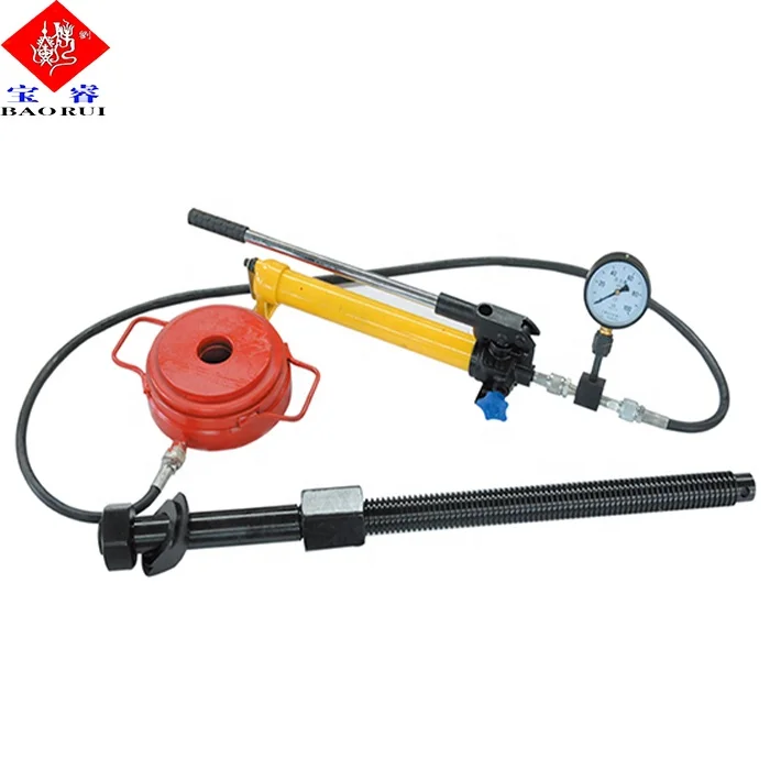
mud pump liner lifting tool free sample
The invention relates to an assembly for quickly securing and releasing a component to a pump housing and more particularly to a retainer assembly for releasably mounting a piston liner within a hydraulic cylinder on the module of a pump.
Heavy duty large horsepower pumps are used to pump fluids or slurries with entrained solids. In the oil industry, for example, slush or mud pumps are used to pump viscous fluids, such as drilling muds, cement, or other well fluids. Although mud pumps may be either centrifugal or reciprocating type pumps, typically mud pumps are reciprocating pumps using one or more pistons and hydraulic cylinders with liners to generate the high pressures required to pump these viscous fluids in and out of the well.
Mud pumps include a fluid end and a power end. In the fluid end of one type of a triplex mud pump, for example, there are three sets of suction modules and discharge modules in fluid communication. A suction manifold is connected to the fluid inlets of the suction modules for receiving fluids and passing those fluids to each of the suction modules. A discharge manifold is connected to the fluid outlets of the discharge modules for discharging the pumped fluids. Each module encloses a set of flow passages with check valves for controlling the direction of flow of the fluids. A check valve is disposed at the suction module fluid inlet to only allow fluids to enter the suction module inlet end of the module and another check valve is disposed at the discharge module fluid outlet to only allow fluids to exit the the discharge module for flow into the discharge manifold.
Each discharge module includes a liner retainer flange attached to the discharge module. The liner retainer flange attaches to a replaceable liner within which a pump piston reciprocates. The piston is a generally cylindrical steel member having a polymer, such as polyurethane, bonded to its outer diameter for sealingly engaging the inner cylindrical wall of the liner to ensure a fluid tight seal required for drawing the low pressure fluids through the suction manifold and module flow passages. The seal integrity must be maintained to withstand the high discharge pressure on the discharge stroke. The power end contains the gears that reciprocate the pump piston within the liner for pumping the fluid through the module passages in the fluid end and thence out the discharge valve.
In operation, on the suction stroke, the pump piston draws fluids through the suction manifold and suction valve as the piston strokes within the liner. On the discharge stroke, the check valve in the discharge module opens simultaneously as the suction valve closes preventing suction back flow into the suction module. Fluid in the liner is compressed and pressure is built up until the pressure overcomes well bore pressure so as to pump the mud into the well. The piston then reverses for another suction stroke whereby the check valve in the suction module opens and the discharge valve closes simultaneously, the piston now making a suction stroke.
As the piston reciprocates within the liner, friction wears the liner. Further, the fluid passing through the fluid end includes particulates and other solids which wear away and destroy the liner and piston. When the liner and piston degrade, the fluid seal is lost and the pump becomes much less efficient. Also, the reciprocation of the piston in the liner causes pulsations that over time cause the liner to become loose within the containment of the liner retainer flange thus resulting in a degradation of the seal at the face of the liner and the seal at the face of the liner wear plate. Therefore, it is important to be able to replace the liner as a part of routine maintenance (or when emergencies occur from seal failure while drilling) to ensure that the pump operates efficiently and can control well pressure. It is also important to have a means for fastening the liner to the liner retainer flange so as to ensure that the liner remains firmly secured despite extended reciprocation of the piston assembly within the liner.
Typically each liner retainer flange, and the cradle of the pump power end are all secured to the fluid end module by studs and threaded connections. Because of the environment in which the mud pump operates and the corrosive nature of the fluids being pumped, the studs and threaded connections, such as nuts, become corroded and are difficult to unthread for the replacement of the liner. Often, the threaded connections have been over tightened, making it even more difficult to unthread. Where the liner is retained by an end cap, a steel bar is inserted into a guide hole in the side of the end cap and then the cap is unscrewed using a significant amount of torque. This end cap is very heavy as it must have sufficient strength to keep the liner from moving, even with pressures up to 7500 psi. Where a nut or end cap resists unscrewing, a sledge hammer is used to hammer on a socket wrench or a special hammer wrench is used to loosen the nut or cap. Such activity is obviously dangerous. In some regions of the world local laws prohibit the use of sledge hammers for personnel safety reasons or to avoid the risk of an explosion due to sparks.
Prior art liner retention systems include spring mechanisms around each stud with an end flange for securing the liner against a fluid end module. Hydraulic pressure is applied to the spring mechanism of each stud by a small hydraulic pump to remove the clamping force of the spring mechanism. The release of the clamping force allows the removal of the clamping flange of the liner retention system. Individually actuated spring loaded studs cause an uneven pressure to be applied to the clamping flange. Further, the clamping force is limited because of the limited space available to hold numerous springs.
The liner retainer assembly of the present invention includes a liner retainer flange that is mounted on the discharge module of the fluid end of a pump. A pressure actuated hydraulic clamping piston with related actuated, conical dished washers and necessary static and sliding seals is disposed within the retainer flange . The hydraulic pressure actuated clamping piston is configured to receive and hold the liner. The hydraulic clamping piston and an end cap maintain the liner in contact with the module during actuation. The hydraulic clamping cylinder includes a counterbore which is divided by the hydraulic piston into a fluid cavity and a spring cavity. The spring cavity houses a plurality of springs which bias the hydraulic piston, end cap, and liner towards the module, thus providing a strong clamping securing force when the hydraulic pressure is released. The fluid cavity communicates with a supply of hydraulic fluid for biasing the hydraulic piston away from the module to activate the springs. By pressurizing the fluid cavity, the springs are compressed so as to disengage the liner retaining end cap from the liner and allow the unthreading of the liner end cap to then remove the liner.
The liner retainer assembly permits preloading or prestressing of the liner against the module of the fluid end of the pump so that the liner will not loosen upon the reciprocation of the pump piston within the liner. Further, the liner may be easily secured and unsecured from the module without the necessity of a sledge hammer or other methods for applying excessive amounts of torque to a securing fitting. The assembly of the present invention permits the easy and quick replacement of the liner as necessary.
FIG. 1 is a cross-sectional view of a typical liner inserted into a liner retaining flange housing assembly constructed in accordance with the present invention.
FIG. 2 is a cross-sectional view and partial exploded view of the liner retaining flange assembly of FIG. 1 illustrating the application of hydraulic pressure for the attachment of a retaining cap.
FIG. 3 is a cross-sectional view of the liner retaining flange assembly of FIGS. 1 and 2 following the attachment of the retaining cap prior to energizing the Belleville washers.
Referring first to FIGS. 1 and 2, there is shown a fluid end module 10 and a cradle 28 of the pump power end. The pump is of the type used to pump fluids, such as drilling muds, cement or the like. Pumps of this type are well known. A wear plate 14 defines a bore 16 which leads into liner 20. The module 10 is used for the transfer of fluid from the suction manifold and suction module (not shown) to the discharge manifold (not shown) and discharge module.
An exemplary liner retaining flange assembly 18 of the present invention is used to secure liner 20 within a hydraulic cylinder 30 mounted on module 10 and liner retainer flange 22. Those of skill in the art will understand that a pump piston (not shown) attached to the power end of the pump is reciprocated within the liner 20 to effect the desired pumping action to flow fluid through the fluid end module 10 of the pump. Hydraulic cylinder 30 provides an open end into which the liner 20 is inserted. Module 10 also provides a counterbore 12 for the adjacent wear plate 14 against which it is desired to retain the liner 20 during operation of the pump piston. It can be appreciated that the purpose of wear plate 14 is to avoid the end of liner 20 wearing module 10 due to the reciprocation of the piston within liner 20. However, wear plate 14 may cause wear to the module 10 if the liner 20 is not securely affixed. Wear plate 14 may be replaced should that wear become excessive. It is noted that the end of the liner 20 adjacent the wear plate 14 includes an internal annular groove 59 with seal member 61 for sealingly engaging the wear plate 14 and the other open end 15 of liner 20 includes an external annular load-bearing shoulder 60 which retains end cap 64 (FIG. 2).
The hydraulic cylinder 30 includes a threaded, reduced diameter portion 24 and an enlarged diameter portion 32. Reduced diameter portion 24 is secured in a threaded or splined relation at 23 to liner retainer flange 22 that is located in an abutting relation to the module 10. Bolted studs 26 secure the cradle 28 of the pump power end, the liner retaining flange 22 and hydraulic cylinder 30 to module 10.
When these components are assembled, the annular flange 44 of piston 42 forms hydraulic cavity 58 and outer spring cavity 35. The hydraulic fluid port and fitting 38 communicates with hydraulic cavity 58 for applying hydraulic pressure to flange 44. The spring cavity 35 houses a plurality of axially compressible Belleville springs or washers 56. Retainer ring 48 has external threads 50 which threadingly mate in a complimentary fashion with the internal threads 34 of enlarged diameter portion 32. The washers 56 bear against the retainer ring 48 and annular flange 44. Enough springs are used so as to insure sufficient force is generated to prevent movement of liner 20 when pump pressure is at maximum. The retainer ring 48 secures the washers 56 and hydraulic piston 42 within the enlarged diameter portion 32 of hydraulic cylinder 30. O-ring 49 provides a fluid-tight seal between the piston 42 and enlarged diameter portion 32.
Upon assembly as shown in FIG. 1, hydraulic piston 42 has previously been inserted into enlarged diameter portion 32 of cylinder 30 to form cavities 58 and 35. Belleville washers 56 are inserted into outer spring cavity 35 and retainer ring 48 is threaded into place. The liner 20 is inserted into the outer hydraulic cylinder 30 of liner retaining assembly 18 so that the end of the liner 20 with seal 61 abuts wear plate 14.
Referring particularly to FIG. 2, the retaining assembly 18 is shown ready to secure the liner 20 in place. A hydraulic hose 62 is secured to the external port and fitting 38 for supplying hydraulic fluid to inner hydraulic cavity 58. As fluid pressure is supplied to cavity 58, fluid pressure is exerted against flange 44 urging piston 42 outward toward retainer ring 48. As annular flange 44 of piston 42 is so moved, springs 56 are axially compressed. As springs 56 are compressed, the threaded end 46 of piston 42 extends further away from wear plate 14 and module 10.
In the outward and extended position of piston 42, end cap 64 is threaded onto the threaded end 46 of the piston 42 so the threads 46 mate with the threads 66 of end cap 64. End cap 64 need only be hand tightened. It is noted that liner load bearing shoulder 60 mates with the shoulder 68 on end cap 64.
Referring now to FIG. 3, the retaining assembly 18 is shown completely assembled with the liner 20 securely affixed within the hydraulic cylinder 30. Once end cap 64 has been affixed, the fluid within the hydraulic cavity 58 is evacuated through port and fitting 38 permitting the springs 56 to bias flange 44 toward wear plate 14 and module 10 and bias end cap 64 against the other end 15 of liner 20. As the hydraulic pressure in the hydraulic cavity 58 is released, stored energy from the compression of springs 56 is released to load the liner 20 longitudinally. As a result, the energy stored by compressing springs 56 is transmitted to the liner 20 in order to load it longitudinally against wear plate 14 and module 10.
In order to remove the liner 20, the procedure is substantially reversed. Fluid is introduced into the hydraulic cavity 58 through port and fitting 38 in the same manner as previously described to compress springs 56 and external piston 42. Once spring forces are removed, end cap 64 may then be unthreaded. Fluid is bled off, springs 56 are decompressed and the unit is stabilized.
It is noted that the arrangement of the present invention permits a liner to be replaced rapidly and easily and without the use of extra tools or having to apply excessive torque. Further, a prestress force is applied to the liner 20 so that it is longitudinally compressed against wear plate 14 and module 10. This load or prestress securely holds the liner 20 against the wear plate 14 despite repeated reciprocation of the pump piston within liner 20.
Referring now to FIGS. 4 and 5, an alternative embodiment for an exemplary retaining assembly 70 is illustrated with the liner 20 inserted and securely affixed therewithin. For simplicity, like reference numerals are used for like or similar components. FIG. 5 is a cross-sectional view of the hydraulic cylinder 36 taken along plane V--V in FIG. 4.
A cover 88 is placed over the open end 15 of liner 20, the cover 88 having a central opening 90 through which liner 20 is disposed. The cover 88 also includes apertures 92 for the disposal of each piston shaft 76. The cover 88 serves to provide a solid surface against which Belleville springs 94 may be compressed. O-ring seals 96 surround the flange 78 of each piston 74 to ensure fluid sealing.
An end cap 98 is shown disposed over the cover 88. The end cap 98, like the cover 88, provides apertures 100 for receiving piston shafts 76. However, the central aperture 102 is only large enough to permit a portion of the liner 20 to be disposed therethrough, creating a shoulder 104 which mates with the shoulder 60 of liner 20.
In operation as shown in FIG. 4, the liner 20 is installed and removed in a manner similar to that described with respect to liner retaining assembly 18. Fluid is introduced into each individual fluid chamber 82 urging the associated piston 74 to move toward the open end 15 of liner 20. Energy is stored through axial compression of the Belleville springs 94. The end cap 98 is placed onto the liner open end 15 so that the shoulder 104 engages shoulder 60 of liner 20. Nuts 86 are then tightened onto each piston 74. Again, the nuts need only be hand tightened. Fluid is then evacuated from the fluid chambers 82 and the Belleville springs 94 bias pistons 74 toward the wear plate 14 and the module 10, thus loading liner 20 longitudinally against wear plate 14 and module 10.
The 2,200-hp mud pump for offshore applications is a single-acting reciprocating triplex mud pump designed for high fluid flow rates, even at low operating speeds, and with a long stroke design. These features reduce the number of load reversals in critical components and increase the life of fluid end parts.
The pump’s critical components are strategically placed to make maintenance and inspection far easier and safer. The two-piece, quick-release piston rod lets you remove the piston without disturbing the liner, minimizing downtime when you’re replacing fluid parts.

Lake Petro provides high quality Mud Pump Parts including Mud Pump Liners, Mud Pump Fluid End Module, piston, Valve and Seat etc. With more than 10 years of experience in the oil and gas industry, we are dedicated to help and support our loyal clients with the most cost-effective and quality Liners and Pistons. We also provide mud pump price and mud pump for sale.
We offer Liners with Ceramic (Zirconia and Aluminium oxide) and Steel (Metal and Bi-metal) materials for all common brands of the mud pump and triplex mud pump.
Bi-metal liners (double metal liners) are made of forged steel shell and wear-resistant sleeve of high chromium iron. In the production process, the size accuracy should be strictly controlled, which can ensure that they can be easily and stably installed. The inner sleeve with high finish and hardness is wear-resistant, corrosion-resistant and has a long service life. The bi-metal liners are suitable for a lot of bad working conditions. Its service life is more than 800 hours.
Ceramic Liners are made of a ceramic inner sleeve and a forged steel outer shell. The service life of ceramic liners is about 4000 to 10000 hours, the minimum time is at least 2000 hours, which is a lot more than bi-metal liners. Because of the phase transformation toughen technology, the ceramic liners have the features of wear-resistance, erosion-resistance, high-pressure-resistance, high hardness and strength. Zirconia type and Alumina type are common type of ceramic sleeve. Compared with Alumina type, Zirconia type liners have better toughness properties and a much longer service life. Piston wear and water consumption for lubrication can be reduced as well.
Seal Rings for Liner packing are also important. Liner Seal Rings is designed and made with hard corner which is an integral part of seal rings and soft nitrile element rubber center. We could provide reliable liner Seal Rings for our customers could order them at the same time.
All Lake Petro liner products are interchangeable with O.E.M. products. Meanwhile, we provide customized Liners according to drawings. Our liners, also with our other mud pump spares, are supplied for use in Honghua, F-Series, Bomco, Emsco and National lines of triplex drilling pumps. Let Lake Petro be your one-stop shop for your whole fleet of pumps. Please refer to “Suitable Pump Models” Lable for more details.

If you run a mud rig, you have probably figured out that the mud pump is the heart of the rig. Without it, drilling stops. Keeping your pump in good shape is key to productivity. There are some tricks I have learned over the years to keeping a pump running well.
First, you need a baseline to know how well your pump is doing. When it’s freshly rebuilt, it will be at the top efficiency. An easy way to establish this efficiency is to pump through an orifice at a known rate with a known fluid. When I rig up, I hook my water truck to my pump and pump through my mixing hopper at idle. My hopper has a ½-inch nozzle in it, so at idle I see about 80 psi on the pump when it’s fresh. Since I’m pumping clear water at a known rate, I do this on every job.
As time goes on and I drill more hole, and the pump wears, I start seeing a decrease in my initial pressure — 75, then 70, then 65, etc. This tells me I better order parts. Funny thing is, I don’t usually notice it when drilling. After all, I am running it a lot faster, and it’s hard to tell the difference in a few gallons a minute until it really goes south. This method has saved me quite a bit on parts over the years. When the swabs wear they start to leak. This bypass pushes mud around the swab, against the liners, greatly accelerating wear. By changing the swab at the first sign of bypass, I am able to get at least three sets of swabs before I have to change liners. This saves money.
Before I figured this out, I would sometimes have to run swabs to complete failure. (I was just a hand then, so it wasn’t my rig.) When I tore the pump down to put in swabs, lo-and-behold, the liners were cut so badly that they had to be changed too. That is false economy. Clean mud helps too. A desander will pay for itself in pump parts quicker than you think, and make a better hole to boot. Pump rods and packing last longer if they are washed and lubricated. In the oilfield, we use a petroleum-based lube, but that it not a good idea in the water well business. I generally use water and dish soap. Sometimes it tends to foam too much, so I add a few tablets of an over the counter, anti-gas product, like Di-Gel or Gas-Ex, to cut the foaming.
Maintenance on the gear end of your pump is important, too. Maintenance is WAY cheaper than repair. The first, and most important, thing is clean oil. On a duplex pump, there is a packing gland called an oil-stop on the gear end of the rod. This is often overlooked because the pump pumps just as well with a bad oil-stop. But as soon as the fluid end packing starts leaking, it pumps mud and abrasive sand into the gear end. This is a recipe for disaster. Eventually, all gear ends start knocking. The driller should notice this, and start planning. A lot of times, a driller will change the oil and go to a higher viscosity oil, thinking this will help cushion the knock. Wrong. Most smaller duplex pumps are splash lubricated. Thicker oil does not splash as well, and actually starves the bearings of lubrication and accelerates wear. I use 85W90 in my pumps. A thicker 90W140 weight wears them out a lot quicker. You can improve the “climbing” ability of the oil with an additive, like Lucas, if you want. That seems to help.
Outside the pump, but still an important part of the system, is the pop-off, or pressure relief valve. When you plug the bit, or your brother-in-law closes the discharge valve on a running pump, something has to give. Without a good, tested pop-off, the part that fails will be hard to fix, expensive and probably hurt somebody. Pop-off valve are easily overlooked. If you pump cement through your rig pump, it should be a standard part of the cleanup procedure. Remove the shear pin and wash through the valve. In the old days, these valves were made to use a common nail as the shear pin, but now nails come in so many grades that they are no longer a reliable tool. Rated shear pins are available for this. In no case should you ever run an Allen wrench! They are hardened steel and will hurt somebody or destroy your pump.
One last thing that helps pump maintenance is a good pulsation dampener. It should be close to the pump discharge, properly sized and drained after every job. Bet you never thought of that one. If your pump discharge goes straight to the standpipe, when you finish the job your standpipe is still full of fluid. Eventually the pulsation dampener will water-log and become useless. This is hard on the gear end of the pump. Open a valve that drains it at the end of every job. It’ll make your pump run smoother and longer.

Whether you’re facing consolidated materials, glacial till, or backfill rubble, quickly complete complex holes to greater depths with the powerful GV5 50K sonic head on our line of sonic drill rigs. Engineered by Geoprobe® to advance up-to 12-inch tooling, the GV5 produces torque required to maintain rotation in tight formations – all backed by a 2-year warranty.
Featuring a proven GH63 percussion hammer and able to use 5-foot tooling, the 6011DT direct push drill rig is still being sized to slip into small spaces.
With the necessary tophead rotation speed, head feed speed, and plenty of mud pump options to get the job done, complete your water well drilling, geothermal drilling, and cathodic protection drilling jobs with a single, compact water well drill.
Outfit as down the hole drill or mud drill with the power of 28.5-foot stroke, 40,000 lb pullback, and 8,000 ft-lb torque to handle deeper wells along with weight of steel casing.
The RIG will be mobilized from XXX to XXX. The rig will be moored in approximately xxx’ water depth. A string of 36” x 1.5” and 1.0" wall structure pipe will be jetted to xxx’ TVD / MD (xxx’ BML). The shallow hazards survey indicates possible low risk shallow gas potential from the mudline to approx. xxx’ TVD (xxx’ BML) and negligible to moderate risk shallow water flow potential at xxx’ TVD / MD (xxx’ BML).
After jetting the 36” structure pipe to the desired depth, the Drill Ahead Tool (DAT) will be used to drill 26” hole to xxx’ TVD / MD (xxx’ BML) and 20” casing will be run and cemented. The shallow water flow study indicates only low to moderate potential for over-pressured sands through this interval. Should a shallow flow be encountered while drilling riserless, 16.0 ppg kill mud will be available on the rig to control any such flow. After running and cementing 20” casing, the subsea BOP stack and riser will be run and tested. Prior to drilling out of the 20” casing, the hole will be displaced with 10.0 ppg synthetic based mud. A LOT of 10.7 ppg is expected at the 20” casing shoe. LWD (GR/RES/APWD/DIR) will be utilized in this hole section.
A 17’’ x 20” hole will be drilled to xxx’ TVD / MD and 16” casing will be run and cemented. This casing string is being set at this depth based on pore pressure and frac gradient. The expected mud weight at casing point is 10.4 ppg and the expected LOT at the 16” casing shoe is 12.4 ppg EMW. LWD (GR/RES/APWD/DIR) will be utilized in this hole section.
A 14 1/2’’ x 17 1/2” hole will be drilled to xxx’ TVD / xxx’ MD. The KOP for the directional work is planned at 7300" TVD/MD. A major azimuth change while building hole angle will be accomplished in this section using rotary steerable tools. A full string of 13 5/8” casing will be set. The expected mud weight at casing point is 12.0 ppg and the expected LOT at the 13 5/8” casing shoe is 14.2 ppg EMW. LWD (GR/RES/APWD/DIR) will be utilized in this hole section.
A 12 1/4’’ x 15" directional hole will then be drilled utilizing rotary steerable tools and LWD (GR/RES/APWD/DEN/NEUT/DIR) to xxx" TVD / xxx" MD. The 1st target zone will be encountered in this hole section at xxx" TVD. A wireline logging program consisting of GR/Dipole Sonic, RCI, and SWC will be run in this hole section. An 9 7/8" liner will be set in this hole section. The expected mud weight at casing point is 13.0 ppg and the expected LOT at the 11 7/8” casing shoe is 14.9 ppg EMW.
A 9 7/8’’ x 12 1/4" directional hole will then be drilled utilizing rotary steerable tools and LWD (GR/RES/APWD/DEN/NEUT/DIR) to xxx" TVD / xxx" MD. The primary target zones will be encountered in this hole section at xxx" TVD and xxx" TVD. A wireline logging program consisting of GR/Dipole Sonic, RCI, and SWC will be run in this hole section. A 9 7/8" liner will be set in this hole section. The expected mud weight at casing point is 14.4 ppg and the expected LOT at the 9 7/8” casing shoe is 15.8 ppg EMW.
An 8-1/2’’ hole will then be drilled to TD at xxx’ TVD / xxx’ MD utilizing rotary steerable tools and LWD (GR/RES/APWD/DEN/NEUT/DIR). The lower target zones will be encountered in this hole section at 14110" TVD and 14506" TVD. A wireline logging program consisting of GR/Dipole Sonic, RCI, SWC, MRILL, Earth Imager, and Check Shot will be run in this hole section. The expected mud weight at TD is
As the rig approaches the actual location, the AHV will begin placement of the 1st anchor. XXX will provide tools, equipment, crews for anchor handling operations, and contingency equipment.
P/U and stand back drill pipe and inner jetting assembly with a rock 26" bit. P/U CADA (Cam-Actuated Drill Ahead) running tool, M/U on wellhead housing and stand back.
Run required joints to allow 280" of penetration BML with 12" of stick up with the gas/mud mat at the ML. Make up connection and torque to recommended optimum torque. (See detailed VETCO procedure in the specific casing program section) Clean threads and apply API modified casing dope.
Make up CADA on inner jetting assembly and land in wellhead housing. Confirm the tool is locked in the housing and the ports in the top of the tool are open.
Pick up the entire structural casing string and wellhead assembly and note the weight. Lower the casing assembly on the landing string until the shoe is located 10" above the mud line as follows:
Start pump at 200 gpm to keep bit nozzles from plugging when tagging mud line. Record string weight. Tag mud line and record depth. Record bull’s-eye angle and direction.
Record the following data on a basis: Time to jet 5", WOB, gpm, psi, comments, and notations on pipe reciprocation (when and how much the pipe was reciprocated) and the pumping of sweeps (volume and viscosity). Also note any overpull while working pipe.
Pump 50 bbl (or slugging pit volume) hi-vis (FV > 100 sec) sweeps of seawater and prehydrated bentonite at each connection (more frequently if needed) and 50 bbl (or slugging pit volume) hi-vis pill at each half stand drilled.
Make a wiper trip to the structural casing shoe with seawater in the hole. Circulate hole clean and displace 150% hole volume with 13.5 ppg CaCl2 spotting mud. To prevent potential wellbore instability, DO NOT place freshwater mud in the hole.
Utilize the blender to increase the mud weight from 12.0 to 14.0 ppg and circulate a minimum of two hole volumes. Circulate at max. rate during kill. Monitor ECD with the APWD readout.
Shut down pumping and monitor well for flow with ROV. If well is still flowing, continue mud weight increase to kill the flow. Once well is dead, options will be discussed with members of the extended drilling team.
If a water flow is encountered, attempt to determine relative severity of flow. If water flow is minimal, consideration will be made to continue drilling to the 20” casing point. If flow is severe, increasing the mud weight or a dynamic kill will be considered. In either case, contact the COMPANY drilling staff to discuss options.
Collapse Caution: It is imperative that the casing string and drill pipe running string be full of fluid while running. Once the 20” shoe has entered the 36” Low Pressure Wellhead Housing, pump at least 1-1/2 casing volumes to assure that the strings are full.
Pick up the 5 1/2" 38 ppf landing string and RIH. Lower the wellhead to the water and pump out all the air from the 20" x inner string annulus. Close the both vent valves on top of the running tool (vent valves should have double valves for redundancy).
Continue running the casing on drill pipe to the mud line, filling the drill pipe every 5 stands. See Figure No. 2 at the end of this section for running weights and tensile capacities.
Wash with weighted mud if needed due to hole conditions. Do not "routinely" wash casing to bottom (avoid displacing the 13.5 ppg mud whenever possible).
Adjust the heave compensator to support about 2,000–3,000 lbs more than running string, WHRT, and cementing stinger weight. Release WHRT per VETCO operations manual and on-site VETCO service technician. When the tool releases, the heave compensator will stroke closed lifting the tool free from the housing.
a) Install the methanol / glycol injection umbilical for the H-4 connector ROV quick stab. Stab umbilical into ROV port. Colored methanol / glycol will be pumped through the umbilical to flush connector cavity at ±7 day intervals. Glycol is preferable.
a) Record hook load every joint while running riser. Also record weights for the TDS/Traveling Block, riser running tool, tensioning ring (if not integral to telescopic joint), and diverter housing/upper flex joint. Send data to Drilling Engineer for review.
The well design with multiple liners provides several areas in which cuttings beds will accumulate. It is advisable to clean these areas during each trip out of the hole.
20" - 25" for rat hole is sufficient below long strings of casing, and 5" is sufficient below the liners. This limits the length of oversized, open hole below casing shoes where cuttings can accumulate. It also prevents excessive cement slump that can detrimentally effect the shoe test upon drilling out that can be a problem given the recommended cement slurry densities vs. the planned section TD MWs.
When pumping a sweep pull the bit off bottom prior to the sweep exiting the bit. Ensure the drill string is at least 60 RPM while the sweep exits the bit. Increase the drill string rotation to a minimum of 120 RPM while pumping the maximum GPM while the sweep is moving up the annulus. Consider pumping piggyback sweeps by using a low vis then high vis sweep.
Always CBU with a maximum pump rate and maximum RPM (if possible above 150 RPM) while reciprocating the pipe. It may take up to 4 times bottoms up to clean the hole. Don’t just circulate a predetermined volume (ie 1.5 bottoms up) but circulate until the hole is clean. Don’t substitute reduced circulating time with the thought that we can backream if we see a problem.
If a tight spot is encountered, DO NOT TURN ON THE PUMPS OR ROTATE AT THE TIGHT SPOT. TIH to clear the BHA from the tight spot. Circulate at max GPM and max rpm for 30 minutes. Again POOH slow without the pumps or rotation. If the tight spot is gone, it was a cuttings bed problem and we just moved it up the hole. Stop and circulate at max GPM with max rpm at least bottoms up until the hole is clean. If the tight spot is still there, then carefully backream as required.
Pumping out of the hole without drill pipe rotation is generally unacceptable and leads to backreaming conditions which often leads to packoffs and lost circulation. Pumping out without rotation can cause a cuttings bed above the BHA. If pumping is needed consider TIH a few stands and maximize GPM and rpm while pumping. Circulate clean then POOH without the pumps or rotation.
Inspect NAF transfer hoses, clean out the mud pits. If more than 10-15 bbl of water remains in the pits, add 1-2 sacks of calcium chloride, and put 40-50 mesh screens on shale shakers for initial circulation of thick NAF.
Pump NAF at 1200 gpm. Reduce rate if pressures are increasing or if returns run over the shakers. Do not stop pumping once the displacement has commenced unless absolutely necessary.
Before drilling the shoe, break circulation and circulate prior to taking slow pump rates. Check and record choke and kill line friction pressures. Perform power choke drill.
Drill out 10" of new hole. To avoid packing-off below the surface casing, pump a 200 bbl x 200 vis super-sweep (to clear the rat hole below the 20" casing) while mechanically disturbing the rat hole area by rotating a bit/stabilizer across the area at high rpm.
Once a LOT is obtained and drilling commences, pump 100 bbl x 200 vis supersweeps as necessary but at least prior to connections for 1st 300" of 17 ½" x 20" hole drilled.
Use 6 ½" mud pump liners and sufficiently large mesh shaker screens to ensure ability to sweep the hole and handle the increased amount of cuttings at the surface.
Pump 100 bbl (or slugging pit volume) viscous and/or weighted NAF "supersweeps" every stand for the first 300" and at least every 2 stands thereafter.
At section TD, perform wiper trip only if warranted by hole conditions. Pump hi-vis weighted sweep and circulate hole clean with a minimum of 2 bottoms up.
Make up and stand back the casing hanger/seal assembly running tool, cementing plug assembly, and the 16" casing hanger and pack off seal. Ensure the lead impression block is used on the VETCO running tool to verify proper seal setting.
Collapse Caution: It is imperative that the casing string and drill pipe running string be full of fluid while running. Once the 16” shoe has entered the wellhead housing, pump at least 1 1/2 casing volumes to assure that the strings are full.
After landing in the casing hanger, makeup the ATC Cement head on drillpipe and begin pumping to close the diverter. The 2 1/4" ball will be on the seat in the Diverter Sub, pressure up to 1000 psi and hold same for 2 to 3 minutes. Continue to increase pump pressure until the ball yields the seat at 2200 to 2600 psi.
The 2 1/4” ball will fall to the ATC Dual Plug System where it will land in a yieldable seat. Pressure up to 600 psi to test the VETCO Subsea Running Tool while shifting the isolation sleeve. Continue to increase the pressure until the seat yields at 800-1200 psi. This will launch the 3 1/2" OD drop ball from the Plug System.
Continue to pump the 3 1/2" ball until it lands in the seat in the Davis-Lynch float collar. Convert the float collar as per Davis-Lynch recommendations. After activating the valves in the float collar, the ball seat assembly will fall to the Guide Shoe.
Approximately 5-10 barrels prior before the bottom DP dart reaching the ATC Diverter Sub slow the pump rate to 5 BPM. The pressure required to yield the seat in the Diverter with the pump down plug should range from 500-800 psi above the circulating rate.
After yielding the seat, continue to pump the Bottom DP dart down to ATC 16” SS Plug System ( Bottom Plug ). The Bottom DP dart will release the Bottom Plug at 800-1400 psi above circulating pressure. After the Bottom Plug is released, continue with the displacement.
When the Bottom ATC Casing Wiper Plug reaches the ATC WPI, 700-1000 psi pressure should be applied to activate the Plug Circulating system. The plug will shift to the open position and displacement can be resumed at normal pumping rates.
Approximately 5-10 barrels prior before the Top DP dart reaching the ATC Diverter Sub slow the pump rate to 5 BPM. The pressure required to yield the seat in the Diverter with the pump down plug should range from 500-800 psi above the circulating rate.
After yielding the seat, continue to pump the Top DP Dart down to ATC 16” Plug System ( Top Plug ). The Top DP dart will release the Top plug at 1400-1800 psi above circulating pressure. After the Top Plug is released, continue with the displacement.
Continue with displacement. Approximately 5-10 barrels prior to the calculated Top Plug displacement to the WPI, slow the pump rate to 3 bbls per minute.
Before drilling the shoe, break circulation and circulate prior to taking slow pump rates. Check and record choke and kill line friction pressures. Perform power choke drill.
Drill out 10" of new hole. To avoid packing-off below the surface casing, pump a 200 bbl x 200 vis super-sweep (to clear the rat hole below the 16" casing) while mechanically disturbing the rat hole area by rotating a bit/stabilizer across the area at high rpm.
Once a LOT is obtained and drilling commences, pump 100 bbl x 200 vis supersweeps as necessary but at least prior to connections for 1st 300" of 14 1/2" x 17" hole drilled.
Use 6 1/4" or 6" mud pump liners and sufficiently large mesh shaker screens to ensure ability to sweep the hole and handle the increased amount of cuttings at the surface.
Pump 100 bbl (or slugging pit volume) viscous and/or weighted NAF "supersweeps" every stand for the first 300" and at least every 2 stands thereafter.
At section TD, perform wiper trip only if warranted by hole conditions. Pump hi-vis weighted sweep and circulate hole clean with a minimum of 2 bottoms up.
Ream undergauge portion of the hole to eliminate excessive rat hole. This will leave approx. 3" of undergauge hole due to bit-NBR spacing. If casing is to be run without logging or another trip for mud conditioning, condition/thin mud properties for casing running.
Make up and stand back the casing hanger/seal assembly running tool, cementing plug assembly, and the 13 5/8" casing hanger and pack off seal. Ensure the lead impression block is used on the VETCO running tool to verify proper seal setting.
After landing in the casing hanger, makeup the ATC Cement head on drillpipe and begin pumping to close the diverter. The 2 1/4" ball will be on the seat in the Diverter Sub, pressure up to 1000 psi and hold same for 2 to 3 minutes. Continue to increase pump pressure until the ball yields the seat at 2200 to 2600 psi.
The 2 1/4” ball will fall to the ATC Dual Plug System where it will land in a yieldable seat. Pressure up to 600 psi to test the VETCO Subsea Running Tool while shifting the isolation sleeve. Continue to increase the pressure until the seat yields at 800-1200 psi. This will launch the 3 1/2" OD drop ball from the Plug System.
Continue to pump the 3 1/2" ball until it lands in the seat in the Davis-Lynch float collar. Convert the float collar as per Davis-Lynch recommendations. After activating the valves in the float collar, the ball seat assembly will fall to the Guide Shoe.
Approximately 5-10 barrels prior before the bottom DP dart reaching the ATC Diverter Sub slow the pump rate to 5 BPM. The pressure required to yield the seat in the Diverter with the pump down plug should range from 500-800 psi above the circulating rate.
After yielding the seat, continue to pump the Bottom DP dart down to ATC 16” SS Plug System ( Bottom Plug ). The Bottom DP dart will release the Bottom Plug at 800-1400 psi above circulating pressure. After the Bottom Plug is released, continue with the displacement.
When the Bottom ATC Casing Wiper Plug reaches the ATC WPI, 700-1000 psi pressure should be applied to activate the Plug Circulating system. The plug will shift to the open position and displacement can be resumed at normal pumping rates.
Approximately 5-10 barrels prior before the Top DP dart reaching the ATC Diverter Sub slow the pump rate to 5 BPM. The pressure required to yield the seat in the Diverter with the pump down plug should range from 500-800 psi above the circulating rate.
After yielding the seat, continue to pump the Top DP Dart down to ATC 16” Plug System ( Top Plug ). The Top DP dart will release the Top plug at 1400-1800 psi above circulating pressure. After the Top Plug is released, continue with the displacement.
Continue with displacement. Approximately 5-10 barrels prior to the calculated Top Plug displacement to the WPI, slow the pump rate to 3 bbls per minute.
Use 6" mud pump liners and sufficiently large mesh shaker screens to ensure ability to sweep the hole and handle the increased amount of cuttings at the surface.
Pump 50 bbl viscous and/or weighted NAF sweeps (FV > 100 sec) every stand for the first 100m and at least every 2 stands thereafter. Occasional sweeps should be pumped to check for cuttings buildup in the hole.
Ream undergauge portion of the hole to eliminate excessive rat hole. This will leave approx. 3" of undergauge hole due to bit-NBR spacing.Condition/thin mud properties for casing running.
Have Weatherford service personnel on location. Inventory all liner equipment and tools prior to running. Double-check all lengths, OD’s, and ID’s, with Weatherford Stab Up Drawing. Verify that all dimensions are compatible with the casing and well bore.
Pump hi-vis weighted sweep and circulate hole clean with a minimum of 2 bottoms up. Condition the mud – DO NOT POOH until mud properties are within required specifications for running casing. Mud rheology may be thinned to below program specs prior to running casing.
Make up and stand back the liner hanger/running tool and cementing plug assembly per instructions of cementing and Weatherford service personnel and their respective Field Service Manuals.
Make up liner hanger assembly. LEAVING ROTARY SLIPS SET ON LINER JOINT, pick up approximately 3 feet to verify that the setting tool and all connections are properly torqued up. Once this has been done, pull slips, slack off until PBR sleeve is accessible from the rig floor. Fill the Floating Junk Bonnet with clean water. DO NOT SET SLIPS ON SETTING SLEEVE / PBR. SET DRILL PIPE SLIPS ON SETTING TOOL LIFT SUB. Make up stand of drill pipe to the liner hanger assembly running tool and lower assembly into well. Record liner weight.
When the 11 7/8” guide shoe reaches the 13 5/8” casing shoe, screw the top drive into the last stand before going out to open hole and get slow pump rates at 15 – 25 – 35 spm through the ATC Diverter Sub. After recording these pressures continue running the liner. Also record liner pick up, slack off, and static weights.
If Liner rotation is anticipated being required in open hole, calculate maximum drill down torque. Liner thread maximum make-up torque, plus rotating torque established at the casing shoe on last trip out of the hole (Step 15 above) minus 20% safety factor = maximum drill down torque. (Rotate slowly at the shoe prior to entering open hole and record minimum torque required to maintain sustained rotation. This torque to be used as reference.
When the liner is one stand off bottom, screw the Top Drive in and start pumping slowly to close the ATC Diverter Sub. Keep the pipe moving down hole during this operation. The 1 3/4" ball will be on the seat so pressure up to 600 psi slowly and hold the same for 2 or 3 minutes. Then continue to increase the pump pressure until the ball yields the seat (1500-1800 psi). Note: You will be TIH very slowly when you perform these steps.
After blowing the ball through the seat go back to circulating at 15 spm and record the pump pressure once the returns have stabilized (Do not exceed 800 psi during this operations – the nominal setting pressure of the WCS liner hanger is 1600 psi). The 1 3/4" ball will drop into the ATC Liner Plug System and rest on top of the 3 1/2” ball.
Start washing the last stand to bottom. Wash the liner within 10" of total depth and stop to finish displacing the cuttings out of the liner (Note: This second pressure should be a minimum of 150 psi greater than the previous pump pressure at 15 spm.
Calculate amount of slack off required to transfer all the liner weight plus 30,000 lbs. of drill pipe weight onto the liner hanger. Space out drill string to put the Cementing Head a minimum of that distance from the rig floor once hanger is hung off and weight slacked off.
After reaching total depth with the liner, pick up ATC Cement Head and make up same. Start circulating at 30 spm, and record the pump pressure once the returns have stabilized.
Establish pick up and slack off weights. Reciprocate liner while circulating and conditioning mud / hole. (If well conditions permit, and operator has given approval, it is recommended that the pipe be reciprocated during the mud / hole conditioning. Ensure that the reciprocation stroke is not long enough to uncover any formation that must be isolated. This will ensure that inadvertently sticking pipe will not leave that formation uncovered. (It is imperative that the driller understand that the reciprocation stroke be a slow steady movement to prevent harmful pressure surges.)
After the liner has been displaced, drop the 2 3/8" setting ball and pump same to ATC Diverter sub to land the ball in the ATC diverter sub. Continue to increase pump pressure until the ball yields the seat at 2200 to 2800 psi.
After blowing the ball through the seat the 2 3/8" ball will drop to the ATC Liner Plug System where the ball will land in a yieldable seat. At that time the WCS rep will pressure up in stages to set the hanger (hydraulic hanger set pressure = 1,600 psi). Hold the pressure while the WCS rep works the liner to check and determine if the Hydraulic Hanger is set.
Shut down circulation. With 10-20,000 lb. of drill string weight down on liner hanger, rotate 6-8 torque free turns to the right to release setting tool from the liner. Pick up stretch in pipe plus 5"-10" to see liner weight loss ensuring that setting tool is released from the liner. Note: Ensure that setting tool is not picked up high enough to remove packer actuator sub from the PBR extension. (Double check pick up on slick joint and Floating Junk Bonnet polish nipple)
Set 30,000 lb. of drill string weight back down on liner hanger, to prevent pump out forces of cement job from inadvertently pumping the setting tool out of the liner. Prepare to cement. (Note: Slack off weight will vary from job to job. The Weatherford serviceman will figure his pump out forces on setting tool and set down sufficient weight to overcome those pump out forces)
After verifying the hanger is set, the ATC rep will pressure up to blow the ball seat in the liner running tool. Continue to increase the pressure until the seat yields at 3400 psi and launches the 3 1/2” drop ball from the liner plug system simultaneously.
Circulate and condition the drilling fluid for the upcoming cement job. Recommend not circulating above 30 strokes per minute until the thick mud is above the liner assembly. Circulate bottoms up (minimum 2 x bottoms up from TD to liner top). Boost riser.
Release the drillpipe dart at the tail of cement. When this dart leaves the cement head we will again see a 1500-2200 psi pressure increase as the dart exits the PLI. Minimum pump rate is 5 bpm at all times.
Displacement will be with mud. NOTE: IF SYNTHETIC DRILLING FLUIDS ARE BEING USED COMPRESSIBILITY FACTORS, IF APPLICABLE, MUST BE ENTERED INTO DISPLACEMENT FIGURES. CONSULT WITH OPERATOR RIG SUPERINTENDENT AND /OR MUD ENGINEER TO OBTAIN THIS INFORMATION.
Approximately 5 barrels prior to the drillpipe dart reaching the ATC Diverter Sub slow the pump rate to 5 bpm . The pressure required to yield the seat with the drillpipe dart should range from 1500 - 2000 psi (above the circulating pressure). After yielding the seat the drillpipe dart will latch the liner wiper plug. The pressure required to release the liner wiper plug will range from 1500 - 2000 psi (above the circulating pressure). Record pressure required to shear the plug. Continue with the displacement.
When the ATC Liner Wiper Plug reaches the WPI, 700 to 1000 psi (above the circulating pressure) should be applied to activate the WPI system. Resume the displacement making appropriate corrections to the total liner displacement if necessary. An additional 150 psi circulating pressure may be seen during this final displacement.
When the plugs reach the float collar, 1000 psi pressure should be applied to the float collar/wiper plug system. Pump calculated displacement volume and do NOT over displace. DO NOT test casing after bumping plug to avoid a wet shoe if plug leaks
Set down minimum of 40000 lbs. (at liner top) to shear pins and energize the TSP packer (The packer actuator sub has rotational capability. Rotate drill string slowly to the right to change friction points and work weight down to the packer. Up to 100000 lbs. can be used to set packer if necessary.
Close rams, and put a quick test on liner top packer (800 – 1,000 psi). Hold test no longer than 3- 5 minutes if cement was calculated to reach up into lap of liner. (NOTE: Verify test procedures with Operator"s rig superintendent. Some operators prefer to reverse out cement prior to putting a test on Liner Top Packer.)
Pick up setting string leaving the end of the setting tool right at the liner top Begin reversing out slowly. Once returns are obtained, pick up slowly until the end of the running tool is approximately 5 feet above the liner top. Increase pump rate and continue to pick up slowly until the end of the running tool is 10-15’ above the liner top. Once sufficient fluid has been reversed out to ensure that all excess cement (Calculated Volume) is out of annulus and either at surface or at least 2,000’ from the end of the setting tool (inside drill pipe), slow pump rate to 1-2 barrels per minute. Slowly slack off setting string inserting the end of slick stinger back into the end of the PBR tie- back extension at least 5-7 ft. Continue circulating for 3-5 minutes and then slowly pick up leaving the slick stinger 5-10 ft above the liner top. Increase pump to desired rate and complete reversing out. Reverse out two drill pipe volumes or until no cement returns are observed. Limit circulating pressure to psi while reversing out to prevent overloading the liner hanger. PRIOR TO JOB VERIFY WITH OPERATOR’S HOUSTON OFFICE THE INTENT TO REVERSE OUT EXCESS CEMENT. VERIFY WITH WEATHERFORD SERVICEMAN LIMITING CIRCULATION PRESSURES.
If liner top did not test (if test was performed), and/or attempts to reverse out results in lost returns and/or pressure loss, or, if TSP packer was not set, DO NOT REVERSE OUT CEMENT AT LINER TOP. PULL 5-10 STANDS THEN REVERSE OUT.
MONITOR REMAINING CEMENT PUMPING TIME AS JOB PROGRESSES. IF LESS THAN 1 HOUR OF CEMENT PUMPING TIME REMAINS (INCLUDE ANTICIPATED REVERSE OUT TIME) WHEN LINER WIPER PLUG BUMPS AND PACKER IS SET, POOH WITHOUT REVERSING OUT CEMENT.
ENSURE THAT SETTING TOOL HAS BEEN PULLED AT LEAST 15 STANDS ABOVE THE LINER TOP WITH NO LESS THAN ½ HOUR OF CEMENT PUMPING TIME REMAINING, IF REVERSING OUT OF EXCESS CEMENT IS NOT COMPLETE.
Pick up and RIH with jet sub, WBRT, and test-type 9 5/8" wear bushing. Wash WH thoroughly with jet sub and jet nozzle joint. Install wear bushing. If seawater was used to displace cement: Circulate out NAF mud from the upper wellhead, BOPS, riser, and choke, kill and booster lines with seawater.
Use 6" mud pump liners and sufficiently large mesh shaker screens to ensure ability to sweep the hole and handle the increased amount of cuttings at the surface.
Pump 50 bbl viscous and/or weighted NAF sweeps (FV > 100 sec) every stand for the first 100m and at least every 2 stands thereafter. Occasional sweeps should be pumped to check for cuttings buildup in the hole.
At section TD, perform wiper trip only if warranted by hole conditions. Pump hi-vis weighted sweep and circulate hole clean with a minimum of 2 bottoms up.
Have Weatherford service personnel on location. Inventory all liner equipment and tools prior to running. Double-check all lengths, OD’s, and ID’s, with Weatherford Stab Up Drawing. Verify that all dimensions are compatible with the casing and well bore.
Pump hi-vis weighted sweep and circulate hole clean with a minimum of 2 bottoms up. Condition the mud – DO NOT POOH until mud properties are within required specifications for running casing. Mud rheology may be thinned to below program specs prior to running casing.
Make up and stand back the liner hanger/running tool and cementing plug assembly per instructions of cementing and Weatherford service personnel and their respective Field Service Manuals.
Make up liner hanger assembly. LEAVING ROTARY SLIPS SET ON LINER JOINT, pick up approximately 3 feet to verify that the setting tool and all connections are properly torqued up. Once this has been done, pull slips, slack off until PBR sleeve is accessible from the rig floor. Fill the Floating Junk Bonnet with clean water. DO NOT SET SLIPS ON SETTING SLEEVE / PBR. SET DRILL PIPE SLIPS ON SETTING TOOL LIFT SUB. Make up stand of drill pipe to the liner hanger assembly running tool and lower assembly into well. Record liner weight.
When the9 7/8” guide shoe reaches the 11 7/8” casing shoe, screw the top drive into the last stand before going out to open hole and get slow pump rates at 15 – 25 – 35 spm through the ATC Diverter Sub. After recording these pressures continue running the liner. Also record liner pick up, slack off, and static weights.
If Liner rotation is anticipated being required in open hole, calculate maximum drill down torque. Liner thread maximum make-up torque, plus rotating torque established at the casing shoe on last trip out of the hole (Step 15 above) minus 20% safety factor = maximum drill down torque. (Rotate slowly at the shoe prior to entering open hole and record minimum torque required to maintain sustained rotation. This torque to be used as reference.
When the liner is one stand off bottom, screw the Top Drive in and start pumping slowly to close the ATC Diverter Sub. Keep the pipe moving down hole during this operation. The 1 3/4" ball will be on the seat so pressure up to 600 psi slowly and hold the same for 2 or 3 minutes. Then continue to increase the pump pressure until the ball yields the seat (1500-1800 psi). Note: You will be TIH very slowly when you perform these steps.
After blowing the ball through the seat go back to circulating at 15 spm and record the pump pressure once the returns have stabilized (Do not exceed 800 psi during this operations – the nominal setting pressure of the WCS liner hanger is 1600 psi). The 1 3/4" ball will drop into the ATC Liner Plug System and rest on top of the 3 1/2” ball.
Start washing the last stand to bottom. Wash the liner within 10" of total depth and stop to finish displacing the cuttings out of the liner (Note: This second pressure should be a minimum of 150 psi greater than the previous pump pressure at 15 spm.
Calculate amount of slack off required to transfer all the liner weight plus 30,000 lbs. of drill pipe weight onto the liner hanger. Space out drill string to put the Cementing Head a minimum of that distance from the rig floor once hanger is hung off and weight slacked off.
After reaching total depth with the liner, pick up ATC Cement Head and make up same. Start circulating at 30 spm, and record the pump pressure once the returns have stabilized.
Establish pick up and slack off weights. Reciprocate liner while circulating and conditioning mud / hole. (If well conditions permit, and operator has given approval, it is recommended that the pipe be reciprocated during the mud / hole conditioning. Ensure that the reciprocation stroke is not long enough to uncover any formation that must be isolated. This will ensure that inadvertently sticking pipe will not leave that formation uncovered. (It is imperative that the driller understand that the reciprocation stroke be a slow steady movement to prevent harmful pressure surges.)
After the liner has been displaced, drop the 2 3/8" setting ball and pump same to ATC Diverter sub to land the ball in the ATC diverter sub. Continue to increase pump pressure until the ball yields the seat at 2200 to 2800 psi.
After blowing the ball through the seat the 2 3/8" ball will drop to the ATC Liner Plug System where the ball will land in a yieldable seat. At that time the WCS rep will pressure up in stages to set the hanger (hydraulic hanger set pressure = 1,600 psi). Hold the pressure while the WCS rep works the liner to check and determine if the Hydraulic Hanger is set.
Shut down circulation. With 10-20,000 lb. of drill string weight down on liner hanger, rotate 6-8 torque free turns to the right to release setting tool from the liner. Pick up stretch in pipe plus 5"-10" to see liner weight loss ensuring that setting tool is released from the liner. Note: Ensure that setting tool is not picked up high enough to remove packer actuator sub from the PBR extension. (Double check pick up on slick joint and Floating Junk Bonnet polish nipple)
Set 30,000 lb. of drill string weight back down on liner hanger, to prevent pump out forces of cement job from inadvertently pumping the setting tool out of the liner. Prepare to cement. (Note: Slack off weight will vary from job to job. The Weatherford serviceman will figure his pump out forces on setting tool and set down sufficient weight to overcome those pump out forces)
After verifying the hanger is set, the ATC rep will pressure up to blow the ball seat in the liner running tool. Continue to increase the pressure until the seat yields at 3400 psi and launches the 3 1/2” drop ball from the liner plug system simultaneously.
Circulate and condition the drilling fluid for the upcoming cement job. Recommend not circulating above 30 strokes per minute until the thick mud is above the liner assembly. Circulate bottoms up (minimum 2 x bottoms up from TD to liner top). Boost riser.
Release the drillpipe dart at the tail of cement. When this dart leaves the cement head we will again see a 1500-2200 psi pressure increase as the dart exits the PLI. Minimum pump rate is 5 bpm at all times.
Displacement will be with mud. NOTE: IF SYNTHETIC DRILLING FLUIDS ARE BEING USED COMPRESSIBILITY FACTORS, IF APPLICABLE, MUST BE ENTERED INTO DISPLACEMENT FIGURES. CONSULT WITH OPERATOR RIG SUPERINTENDENT AND /OR MUD ENGINEER TO OBTAIN THIS INFORMATION.
Approximately 5 barrels prior to the drillpipe dart reaching the ATC Diverter Sub slow the pump rate to 5 bpm . The pressure required to yield the seat with the drillpipe dart should range from 1500 - 2000 psi (above the circulating pressure). After yielding the seat the drillpipe dart will latch the liner wiper plug. The pressure required to release the liner wiper plug will range from 1500 - 2000 psi (above the circulating pressure). Record pressure required to shear the plug. Continue with the displacement.
When the ATC Liner Wiper Plug reaches the WPI, 700 to 1000 psi (above the circulating pressure) should be applied to activate the WPI system. Resume the displacement making appropriate corrections to the total liner displacement if necessary. An additional 150 psi circulating pressure may be seen during this final displacement.
When the plugs reach the float collar, 1000 psi pressure should be applied to the float collar/wiper plug system. Pump calculated displacement volume and do NOT over displace. DO NOT test casing after bumping plug to avoid a wet shoe if plug leaks
Set down minimum of 40000 lbs. (at liner top) to shear pins and energize the TSP packer (The packer actuator sub has rotational capability. Rotate drill string slowly to the right to change friction points and work weight down to the packer. Up to 100000 lbs. can be used to set packer if necessary.
Close rams, and put a quick test on liner top packer (800 – 1,000 psi). Hold test no longer than 3- 5 minutes if cement was calculated to reach up into lap of liner. (NOTE: Verify test procedures with Operator"s rig superintendent. Some operators prefer to reverse out cement prior to putting a test on Liner Top Packer.)
Pick up setting string leaving the end of the setting tool right at the liner top Begin reversing out slowly. Once returns are obtained, pick up slowly until the end of the running tool is approximately 5 feet above the liner top. Increase pump rate and continue to pick up slowly until the end of the running tool is 10-15’ above the liner top. Once sufficient fluid has been reversed out to ensure that all excess cement (Calculated Volume) is out of annulus and either at surface or at least 2,000’ from the end of the setting tool (inside drill pipe), slow pump rate to 1-2 barrels per minute. Slowly slack off setting string inserting the end of slick stinger back into the end of the PBR tie- back extension at least 5-7 ft. Continue circulating for 3-5 minutes and then slowly pick up leaving the slick stinger 5-10 ft above the liner top. Increase p


 8613371530291