
mud pump liner material free sample

Alibaba.com offers 1112 mud pump liner products. About 56% % of these are mud pump, 7%% are mining machine parts, and 3%% are other oil field equipments.
A wide variety of mud pump liner options are available to you, You can also choose from oil well, mud pump liner,As well as from carbon steel, chromium, and iron. and whether mud pump liner is moulding, bending, or punching.
Mud pump liner selection in today"s drilling operations seldom (at best) considers electrical implications. Perhaps, with more available useful information about the relationships between mud pump liner size and operational effects on the electrical system, certain potential problems can be avoided. The intent of this paper is to develop those relationships and show how they affect an electrical system on example SCR rigs.Introduction
There, seems to be little consideration for the relationships between liner size and demand on a rig"s engine/generator set(s). Yet, consideration for this relationship can prove to be very helpful to drillers and operators in efficiency of a rig"s electrical system. In order to develop the relationships and help drillers and operators understand the importance of each, relationships between liner size, pump speed, pump pressure, and electrical power will be developed. Only basic physical laws will be used to develop the relationships; and, once developed, the relationships are readily applied to realistic examples utilizing a mud pump manufacturer"s pump data. Finally, conclusions will be drawn from the examples.DEVELOPMENT OF RELATIONSHIPS BASIC RELATIONSHIPS
where HHP= Hydraulic horsepower, GPM = Mud pump volumetric flow rate in gallons per minute, and PST Mud pump output pressure in pounds peer square inch.
Hydraulic horsepower is reflected to the mud pump motor via a multiplier for mechanical efficiency. it follows that motor horsepower is then represented by
Internal cavities of metal objects frequently require a cladding, or a coating, that is more corrosion, oxidation and/or wear resistant than the metal object itself. This need may arise in some cases due to high temperatures created within the cavity, exposure to a corrosive or abrasive liquid, and/or to rubbing action of an internal machine member such as a piston. An example of such a metal object is the liners in mud pumps used in oil field drilling. A mud pump is a part of the oil or gas well drilling fluid circulating system, one of five major components of a rotary drilling operation. The other components are the drill string and bit, the hoisting system, the power plant and the blowout prevention system.
Drilling fluid, usually called the "mud", in most cases consists of a mixture of water, various special chemicals including corrosion inhibitors and solid particles such as Barite to increase its density. Such fluid is continuously circulated down the inside of the drill pipe, through the bottom of the bit and back up the annular space between the drill pipe and the hole. The driving force is provided by a mud pump.
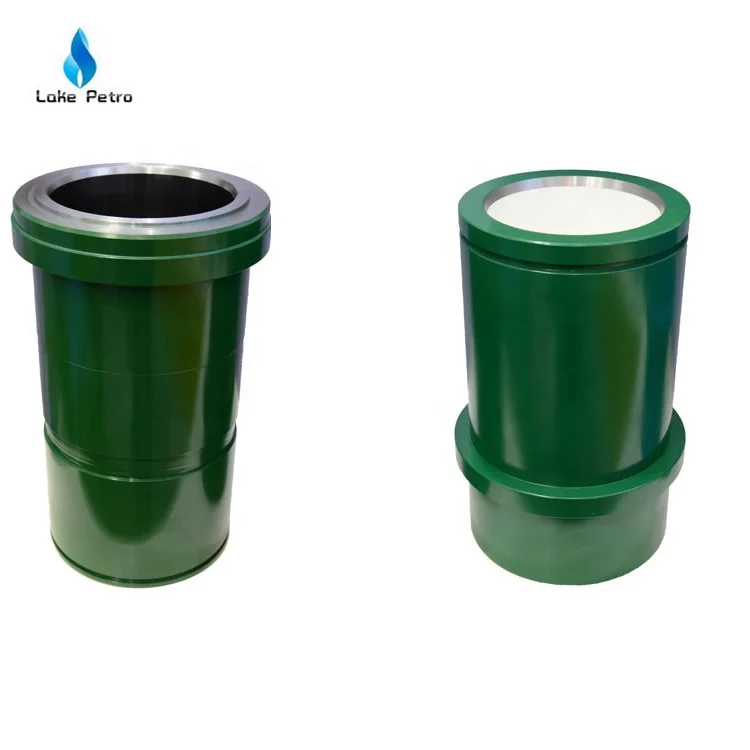
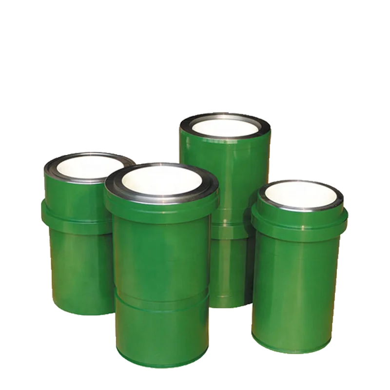
A mud pump liner is basically a heavy wall pipe section with one or two retaining rings at its outer diameter. It is the wear resistance of the inner surface that determines the liner service life. Consequently, the internal surface of the liner is desirably clad with a wear resistant material. The internal cladding layer is subjected to sliding wear by the rubber piston which can wear and cause metallic structure supporting the rubber to contact the liner cladding, thus accelerating the wear process. The cladding material is also subjected to corrosion from the drilling fluid, and metal fatigue caused by cyclic loading, especially at areas where the direction of the piston motion suddenly changes, Further, micro regions of cladding may experience sudden pressurization and depressurization. These operating conditions impose stringent metallurgical requirements on the cladding materials. An ideal cladding material should, therefore, possess high hardness and high resistance to corrosion, impact and metal fatiuge. Such properties are desirably achieved by a uniform, fine grained microstructure, which has been the goal of pump liner makers of many years.
The outer, heavy wall portions of the commercially available mud pump liners typically consist of either a carbon steel, or a low alloy steel; and the liner cladding is, in most cases, a cast sleeve of iron--28% chromium alloy. The sleeve can be centrifugally cast into the steel pipe section or cast separately as a pipe, and shrink fitted into the outer pipe section, then machined to a smooth finish. These manufacturing procedures are lengthy and costly, while providing only a cast metal microstructure which is known to be chemically nonuniform, since in castings the solidification process results in natural segregation of the elemental species contained in the alloy. Furthermore, the cladding thicknesses are kept undesirably large to allow casting processes to be used. The claddings within metallic objects other than pump liners can be similarly characterized and most likely be prone to the same deficiencies.
It is a major object of the invention to provide a powder metal cladding method and apparatus for cladding the internal cavity surface of metal liners and objects, overcoming the above problem and deficiencies. In addition, the invention provides various material combinations for the production of pump liners and internally clad pipe segments for use with oilfield mud pump fluids. There are many other products that can benefit from this processing technique.
As will appear, pressurization of the grain is typically carried out by transmitting force to the grain along a primary axis, the layer extending about that axis and spaced therefrom, whereby force is transmitted by the grain away from the axis and against said layer. To this end, the method contemplates providing a die having a first chamber receiving said object, the die having a second chamber containing grain communicating with grain in the cavity, pressurizing of the grain in the cavity being carried out by pressurizing the grain in the second chamber, as for example by transmitting pressure from the grain in the second chamber to only a medial portion of the grain in the first chamber everywhere spaced from said layer. Further, the metal object is typically cylindrical, the layer being applied on an internal cylindrical surface of said object, the latter for example comprising a mud pump liner.
Referring first to FIG. 1, and alloy steel mud pump liner 10 comprises an elongated tube 11 having an outer flange 12 on one end portion. The tube axis appears at 13, and the tube inner cylindrical surface at 14. Tube 11 may be considered to represent other metal objects having interior surfaces (as at 14) facing internal cavities 15.
Internal surfaces of the tube or metal object to be clad are first cleaned to remove any oxide layers, grease or dirt; then, using a slurry of the cladding metal powder and a suitable fugitive binder, these surfaces are coated with the slurry, the coating appearing at 16. As shown, the "green" coating is generally cylindrical, and has an outer surface 16a contacting the tube surface 14. The coating process can be accomplished by spraying, dipping in the slurry, brush, or spatula painting, or if the internal cavity is cylindrical, as is the case for pipes, the slurry may be centrifugally spread onto the internal surface by high speed spinning of the part. The thickness of the "green", weakly held together, powder metalbinder mixture can be controlled to some degree by controlling the total weight of the slurry used. Localized surfaces where cladding is not desired can be masked using adhesive tapes (see tape 17) which are removed after slurry coating is applied. The green coating is then dried at or near room temperature and heated to a temperature (between 1600° F. and 2300°F.) where the coated metal powders are easily deformable under pressure. For most materials the furnace atmosphere should be either inert or reducing to prevent oxidation of the powder. Such a furnace is indicated at 18, and it may contain inert gas such as argon or nitrogen.
Referring to FIG. 2, the next step in the process is to place the liner containing the green now lightly sintered layer 11a within a step die 19 where the liner fits into the large cavity (i.e. first chamber 19) in the die as shown in the figure, and having inner cylindrical walls 19a and 19b. The die second chamber 20 throat diameter D1 should be equal to or smaller than the "green" internal diameter D2 of the mud pump liner 11a. This assures relatively shearless pressing of the green powder metal cladding 11a under largely lateral pressure during the pressurizing step. Chamber 20 has a bore 20a.
As seen in FIG. 3, pressurization takes place in a press 21 after filling both the die and the pump liner cavities with a refractory powder 22 already at a temperature near or above the consolidation temperature of the cladding powder. The pressure from ram 23 is transmitted to the liner by the horizontal forces created within the refractory powder grains. In this regard, the second chamber 20 is in axial alignment with the first chamber 19, the second chamber having a cross section less than the cross section of the first chamber, whereby pressure is transmitted from the grain 22a in the second chamber to only a medial portion of the grain 22b in the first chamber which is everywhere spaced from layer 11a. Therefore, lateral pressurizing of the grain in the cavity 19 is affected by grain pressurized longitudinally in the second chamber, and no destructive shear is transmitted to layer 11a.
In one example the cladding material consisted of Stellite alloy (98.5% by wt.) No. 1 powder (see item 2, below Table 1 for chemistry) mixed with 1.5% by weight cellulose acetate and acetone in an amount to establish sufficient fluidity to the mixture. This mixture was spun at 500 rpm to provide a thin (approximately 1/10th of an inch) green coating inside a 1.5" long×3.25" wall tube. The tubing was allowed to dry at room temperature overnight and heated to 2250° F. for about 14 minutes. The furnace atmosphere was substantially hydrogen. Immediately after the tube was placed in the die cavity, the refractory grain which was heated to 2300° F. in a separate furnace was poured and the press ram was allowed to pressurize the grain. After a peak pressure of 45 tons per square inch was reached for about 10 seconds, the pressurization cycle was considered complete and pressure was released. The die was then moved to a location where its contents could be emptied. In this example the cladding of the Stellite Alloy No. 1 accomplished satisfactorily while the Stellite powder was consolidated to near 100% of its theoretical density. A photomicrograph of the bonding interface is shown in FIG. 4.
Other applications utilizing various cladding materials to clad internal cavities of other metal objects such as valves, tubes, rock bits, etc. can be accomplished as well.
The process, while remaining basically the same, may have some variations. For example, there may be an insulating material positioned between the part (the pump liner in FIG. 2) and the die to reduce heat loss before pressing.
The insulating material may be a ceramic, high density graphite or a metal which may be heated together with the part. If the insulating material is a metal, a non-bonding refractory powder parting compound may be applied on the insulating material. In addition, the die itself may be a vertically split die to ease the positioning of the part within it when the part shape is more complicated than a simple cylinder. Other minor variations of the process and the die may be utilized as well.

The 2,200-hp mud pump for offshore applications is a single-acting reciprocating triplex mud pump designed for high fluid flow rates, even at low operating speeds, and with a long stroke design. These features reduce the number of load reversals in critical components and increase the life of fluid end parts.
The pump’s critical components are strategically placed to make maintenance and inspection far easier and safer. The two-piece, quick-release piston rod lets you remove the piston without disturbing the liner, minimizing downtime when you’re replacing fluid parts.
The piston is one of the parts that most easily become worn out and experience failure in mud pumps for well drilling. By imitating the body surface morphology of the dung beetle, this paper proposed a new type (BW-160) of mud pump piston that had a dimpled shape in the regular layout on the piston leather cup surface and carried out a performance test on the self-built test rig. Firstly, the influence of different dimple diameters on the service life of the piston was analyzed. Secondly, the analysis of the influence of the dimple central included angle on the service life of the piston under the same dimple area density was obtained. Thirdly, the wear of the new type of piston under the same wear time was analyzed. The experimental results indicated that the service life of the piston with dimples on the surface was longer than that of L-Standard pistons, and the maximum increase in the value of service life was 92.06%. Finally, the Workbench module of the software ANSYS was used to discuss the wear-resisting mechanism of the new type of piston.
The mud pump is the “heart” of the drilling system [1]. It has been found that about 80% of mud pump failures are caused by piston wear. Wear is the primary cause of mud pump piston failure, and improving the wear-resisting performance of the piston-cylinder friction pair has become the key factor to improve the service life of piston.
Most of the researchers mainly improve the service life of piston through structural design, shape selection, and material usage [1, 2]. However, the structure of mud pump piston has been essentially fixed. The service life of piston is improved by increasing piston parts and changing the structures of the pistons. However, the methods have many disadvantages, for example, complicating the entire structure, making piston installation and change difficult, increasing production and processing costs, and so on. All piston leather cup lips use rubber materials, and the material of the root part of the piston leather cup is nylon or fabric; many factors restrict piston service life by changing piston materials [3]. Improving the component wear resistance through surface texturing has been extensively applied in engineering. Under multiple lubricating conditions, Etsion has studied the wear performance of the laser surface texturing of end face seal and reciprocating automotive components [4–6]. Ren et al. have researched the surface functional structure from the biomimetic perspective for many years and pointed out that a nonsmooth surface structure could improve the wear resistance property of a friction pair [7, 8]. Our group has investigated the service life and wear resistance of the striped mud pump piston, and the optimal structure parameters of the bionic strip piston have improved piston service life by 81.5% [9]. Wu et al. have exploited an internal combustion engine piston skirt with a dimpled surface, and the bionic piston has showed a 90% decrease in the average wear mass loss in contrast with the standard piston [10]. Gao et al. have developed bionic drills using bionic nonsmooth theory. Compared with the ordinary drills, the bionic drills have showed a 44% increase in drilling rate and a 74% improvement in service life [11]. The present researches indicate that microstructures, like superficial dimples and stripes, contribute to constituting dynamic pressure to improve the surface load-carrying capacity and the wear resistance of the friction pair [12–21].
In nature, insects have developed the excellent wear-resistant property in the span of billions of years. For instance, the partial body surface of the dung beetle shows an irregularly dimpled textured surface with the excellent wear-resistant property that is conducive to its living environment [7, 8, 22]. The dung beetle, which is constantly active in the soil, shows a body surface dimple structure that offers superior drag reduction. These dimples effectively reduce the contact area between the body surface and the soil. Moreover, the friction force is reduced. Therefore, the dung beetle with the nonsmooth structure provides the inspiration to design the bionic mud pump piston. This paper proposed a new type of piston with dimpled morphology on its surface and conducted a comparative and experimental study of different surface dimpled shapes, thus opening up a new potential to improve the service life of the mud pump piston.
A closed-loop circulatory system was used in the test rig, which was built according to the national standard with specific test requirements. The test rig consisted of triplex single-acting mud pump, mud tank, in-and-out pipeline, reducer valve, flow meter, pressure gauge, and its principle, as shown in Figure 1. Both the pressure and working stroke of the BW-160 mud pump are smaller than those of the large-scale mud pump, but their operating principles, structures, and working processes are identical. Therefore, the test selected a relatively small BW-160 triplex single-acting mud pump piston as a research object, and the test results and conclusion were applicable to large-scale mud pump pistons. The cylinder diameter, working stroke, reciprocating motion velocity of piston, maximum flow quantity, and working pressure of the BW-160 triplex single-acting mud pump were 70 mm, 70 mm, 130 times/min, 160 L/min, and 0.8–1.2 MPa, respectively.
The mud pump used in the test consisted of water, bentonite (meeting the API standard), and quartz sand with a diameter of 0.3–0.5 mm according to actual working conditions. The specific gravity of the prepared mud was 1.306, and its sediment concentration was 2.13%. Whether mud leakage existed at the venthole in the tail of the cylinder liner of the mud pump was taken as the standard of piston failure. Observation was made every other half an hour during the test process. It was judged that the piston in the cylinder failed when mud leaked continuously; its service life was recorded, and then it was replaced with the new test piston and cylinder liner. The BW-160 mud pump is a triplex single-acting mud pump. The wear test of three pistons could be simultaneously conducted.
The mud pump piston used in the test consisted of a steel core, leather cup, pressing plate, and clamp spring. The leather cup consisted of the lip part of polyurethane rubber and the root part of nylon; the outer diameter on the front end of the piston was 73 mm, and the outer diameter of the piston tail was 70 mm, as shown in Figure 2. We proceeded in two parts during the design of the dimpled layout pattern because the piston leather cup consisted of two parts whose materials were different. The dimples at the lip part of the leather cup adopted an isosceles triangle layout pattern, and the dimples at the root part were arranged at the central part of its axial length, as shown in Figure 3(a). Dimple diameter (D, D′), distance (L), depth (h), and central included angle (α) are shown in Figure 3. The dimples on the piston surface were processed by the CNC machining center. Since then, the residual debris inside the dimples was cleaned.
Table 1 shows that average service lives of L-Standard, L-D1, L-D2, and L-D3 were 54.67 h, 57.17 h, 76.83 h, and 87.83 h, respectively. Therefore, the mud pump pistons with dimples provide longer service life than the L-Standard piston. As the dimple diameter increases, the piston service life was improved, and the largest percentage increase of the service life was 60.65%. The service life of the L-D4 piston was about 81.17 h, which increased by 7.94% compared with that of the L-D2 piston, indicating that the piston with dimples at the leather cup root could improve piston service life.
Figure 4 illustrates the surface wear patterns of pistons with different dimple diameters in the service life test. Figures 4(a) and 4(a′) show wear patterns on the surface of the L-Standard piston. This figure shows that intensive scratches existed in parallel arrangement on the piston leather cup surface, enabling high-pressure mud to move along the scratches from one end of the piston to the other easily, which accelerated the abrasive wear failure with the abrasive particles of the piston. Figures 4(b), 4(b′), 4(c), 4(c′), 4(d), and 4(d′) show the wear patterns of the leather cup surfaces of L-D1, L-D2, and L-D3 pistons, respectively. Figures 4(b), 4(b′), 4(c), 4(c′), 4(d), and 4(d′) show that the scratches on the leather cup surface became shallower and sparser and the surface wear patterns improved more obviously as the dimple diameter increased. If the piston leather cup surface strength was not affected to an extent as the dimple diameter increased, the reduced wear zone near the dimple would become greater and greater, indicating that the existence of dimples changed the lubricating status of the leather cup surface, their influence on nearby dimpled parts was more obvious, and they played active roles in improving the service life of the piston.
Figure 5 displays the wear patterns of the leather cup root parts of the L-D4 and L-D2 test pistons. The wear patterns of the nylon root parts of the L-D4 pistons are fewer than those of the L-D2 pistons, as shown in Figure 5. When the leather cup squeezed out high-pressure mud as driven by the piston steel core, it experienced radial squeezing while experiencing axial wear. Therefore, the area with the most serious wear was the piston leather cup root part, and the friction force at the leather cup root was much greater than that at the other areas. The rapid wear at the root decreased the piston load-carrying capacity and then affected the service life of piston. The dimples at the piston leather cup root could reduce the wear of the piston leather cup root and improve the service life of piston.
Figure 6 shows the surface wear patterns of the L-S1 and L-S2 test pistons. In Figures 6(a) and 6(a′), the scratches on the piston leather cup surface became sparse and shallow in the dimpled area. Figures 6(b) and 6(b′) show that the wear was slight in the area close to the dimples. The farther the scratches were from the dimpled area, the denser and deeper the scratches would be. The L-S1 piston had a small dimple central included angle, which was arranged more closely on the piston surface. The lubricating effects of oil storage in each row of dimples were overlaid very well, which was equivalent to amplifying the effect of each row of dimples in Figure 6(b), making the wear on the whole piston leather cup surface slight, preventing the entry of high-pressure mud into the frictional interface, and lengthening the service life of piston.
During the operation of the mud pump piston, the outside surface of the piston leather cup comes in contact with the inner wall of the cylinder liner and simultaneously moves to push the mud. The lip part of the piston leather cup mainly participated in the piston wear and exerted a sealing effect, while the piston root part mainly exerted centralizing and transitional effects. In the mud discharge stroke, the lip part of the piston experienced a “centripetal effect,” and a gap was generated between the lip part and the cylinder liner. The greater the contact pressure between the lip part and cylinder liner of the piston was, the smaller the gap was, and the entry of high-pressure mud into the contact surface between the piston and cylinder liner was more difficult. The piston root easily experienced squeezing under high pressure, and the smaller the equivalent stress caused by the piston root was, the more difficult the squeezing to occur. Hence, the contact pressure at the lip part of the piston and the equivalent stress at the root were analyzed, and they would provide a theoretical basis for the piston wear-resisting mechanism. The ANSYS Workbench module was used to perform a comparative analysis between the contact pressure at the lip part and the equivalent stress at the root of the three kinds of pistons (i.e., L-Standard piston, L-S1 piston, and L-D1 piston). The service life of the L-S1 piston exhibited the best improvement effect, whereas that of the L-D1 piston demonstrated the worst improvement effect. The piston adopted a 1 mm hexahedral grid, and the grid nodes and elements are as shown in Table 4.
The contact pressure nephograms of the three pistons indicate that the dimpled structure on the piston surface changed the distribution state of contact pressure. Three nodes were selected at the same position of each piston to obtain the contact pressure values. The node positions are shown in Figure 8(c), and the average pressure value of three nodes was the pressure value at the lip part of this piston. The contact pressure value of the L-Standard piston was 0.6027 MPa and that of the L-D1 and L-S1 pistons was 0.6840 MPa and 1.0994 MPa, respectively. Compared with the L-Standard piston, the contact pressure at the lip part of the L-S1 piston increased, the gap between the piston and cylinder liner became small, which could effectively prevent abrasive particles from participating in the wear and resulting in piston failure, and there was greater improvement in the service life of piston. The contact pressure of the L-D1 piston did not increase too much, and the degree of improvement of the piston service life was not obvious.
The lubricating oil on the mud pump piston surface could reduce the wear of piston and cylinder liner and improve the service life of pistons with the reciprocating movement. The lubricating oil would eventually run off and lose lubricating effect, which would result in piston wear. The finite element fluid dynamics software CFX was used to establish the fluid domain model of the dimpled and L-Standard pistons and analyze the lubricating state on the piston surface. The piston surface streamlines are shown in Figure 10. This figure shows that the lubricating fluid did not experience truncation or backflow phenomenon when passing the surface of the L-Standard piston. When the lubricating fluid flowed through the surface of the dimpled piston, it presented a noncontinuous process. Its flow velocity at the dimpled structure slowed down obviously because it was blocked by the dimpled structure.
Figure 11 shows the piston cross section streamline. This figure shows that the existence of dimples changed the distribution status of the lubricating flow fields on the contact surface between the piston and cylinder liner. The lubricating oil entered the dimpled structure in a large quantity, and the flow velocity slowed down. The dimpled structure on the piston surface enlarged the storage space of the lubricating oil and made it difficult for the lubricating oil inside the dimpled structure to be taken away by the cylinder liner to improve the lubricating conditions of the friction pair interface, reduce the frictional resistance between the piston and cylinder liner, reduce wear, and improve the piston service life.
When the piston moved in the cylinder liner, a small quantity of solid particles in mud entered gap of piston and cylinder liner and participated in abrasion. The dimpled structure on the piston surface could store some abrasive particles (as shown in Figure 6(a′)) during the piston wear process to prevent these particles from scratching the piston and cylinder liner and generating gullies, thus avoiding secondary damage to the piston and cylinder liner and improving the piston service life.
This paper presented a dimpled-shape mud pump piston; that is, the piston leather cup surface had a dimpled array morphology in regular arrangement. The experimental results can provide the basic data for design engineering of the mud pump piston with a long service life. The comparative analyses of service life and wear patterns for dimpled mud pump pistons and L-Standard pistons were conducted. The main results and conclusions were summarized as follows:(1)The service life of the mud pump piston with dimpled morphology on the surface improved in comparison with that of the L-Standard piston, and the service life increase percentages were from 4.57% to 92.06%.(2)The piston service life would increase with the dimple diameter under the same dimpled arrangement pattern, and the maximum increase in the value of service life was 60.65%.(3)The service life of the piston with dimples increased by 7.94% in comparison with that with none.(4)Under the same dimpled arrangement patterns and area densities, the tighter and closer the dimples were arranged on the piston surface, the longer the service life of piston was, and the maximum increase in the value of service life was 92.06%.(5)Under the same wear time, the wear of the dimpled piston slightly decreased in comparison with that of the L-Standard piston, and the minimum value of wear mass percentage was 3.83%.(6)The dimpled shape could not only change the stress state of the piston structure, improve piston wear resistance, and reduce root squeezing, but also increase oil storage space, improve lubricating conditions, and enable the accommodation of some abrasive particles. Furthermore, the dimpled shape was the key factor for the service life improvement of the mud pump piston.

Geoprobe® submitted samples of our clear PVC soil liners, including the lay flat liners used for sonic soil sampling, to Jennifer Field, Ph.D., at Oregon State University and her research team. Field’s team analyzed the Geoprobe® soil liners for 52 PFAS compounds, including PFOS and PFOA. The PVC liners tested nondetect for all 52 compounds. The research concluded that field sampling materials are an unlikely source of contamination for Perfluoroalkyl and Polyfluoroalkyl substances in field samples.
Geoprobe® Screen Point (SP) Groundwater Samplers are a mainstay of contaminant site investigations. This tool has become standard equipment for direct push operators since its introduction in the 1990s. The magic of the SP system is its ability to deliver a protected sampling screen to depth and then to “open” or expose that screen to the formation. Improving field performance, particularly when sampling for PFAS contamination, Geoprobe® has developed groundwater screen point (SP) latching samplers. These enhancements to the time-tested Geoprobe® SP groundwater sampling system provide a secure seal within the zone you"re pumping, allowing you to use a mechanical bladder pump or other sample line to obtain a higher-quality sample. Options available in three sizes: SP16, SP19 and SP22.
Geoprobe® recommends you conduct periodic field rinsate samples of tools and soil liners during your PFAS sampling projects. You must use PFAS free water provided by your laboratory for this purpose. Tap water or bottled water may have been in contact with PFAS containing materials such as Teflon® tape or PTFE containing pipe joint compound. Of course, use bottles (HDPE or Polypropylene) provided by your lab for the PFAS field rinsate samples.
The steel components of soil samplers and groundwater sampling tools do not contain PFAS compounds. Use of these tools for PFAS sampling and investigation following standard procedures is appropriate. Be careful to NOT use materials like Teflon® tape or PTFE joint compound on joints or fittings that will have sample contact. Don’t use Teflon® soil liners or tubing in your sampling for PFAS. Use the clear PVC soil liners when soil sampling or HDPE or polypropylene tubing when groundwater sampling. The DOD has recommended the use of silicon-based plumbers paste and O-rings in place of Teflon® products. Also, the DECON 90 product contains PFAS components so use decon soap and water approved for PFAS sampling. We are all coming up the PFAS learning curve. As the entire industry continues to learn about PFAS sampling, analysis, and remediation, updates and revisions to guidance documents and operating procedures will be issued.


 8613371530291