
mud pump liner output free sample

Rig pump output, normally in volume per stroke, of mud pumps on the rig is one of important figures that we really need to know because we will use pump out put figures to calculate many parameters such as bottom up strokes, wash out depth, tracking drilling fluid, etc. In this post, you will learn how to calculate pump out put for triplex pump and duplex pump in bothOilfield and Metric Unit.

Oil and Gas drilling process - Pupm output for Triplex and Duplex pumpsTriplex Pump Formula 1 PO, bbl/stk = 0.000243 x ( in) E.xample: Determine the pump output, bbl/stk, at 100% efficiency for a 7" by 12". triplex pump: PO @ 100%,= 0.000243 x 7 x12 PO @ 100% = 0.142884bbl/stk Adjust the pump output for 95% efficiency: Decimal equivalent = 95 + 100 = 0.95 PO @ 95% = 0.142884bbl/stk x 0.95 PO @ 95% = 0.13574bbl/stk Formula 2 PO, gpm = [3(D x 0.7854)S]0.00411 x SPM where D = liner diameter, in. S = stroke length, in. SPM = strokes per minute Determine the pump output, gpm, for a 7" by 12". triplex pump at 80 strokes per minute: PO, gpm = [3(7 x 0.7854) 1210.00411 x 80 PO, gpm = 1385.4456 x 0.00411 x 80 PO = 455.5 gpm
Example:Duplex Pump Formula 1 0.000324 x (liner diameter, in) x ( stroke lengh, in) = ________ bbl/stk -0.000162 x (rod diameter, in) x ( stroke lengh, in) = ________ bbl/stk Pump out put @ 100% eff = ________bbl/stk Example: Determine the output, bbl/stk, of a 5 1/2" by 14" duplex pump at 100% efficiency. Rod diameter = 2.0": 0.000324 x 5.5 x 14 = 0.137214bbl/stk -0.000162 x 2.0 x 14 = 0.009072bbl/stk Pump output @ 100% eff. = 0.128142bbl/stk Adjust pump output for 85% efficiency: Decimal equivalent = 85 100 = 0.85 PO@85%)= 0.128142bbl/stk x 0.85 PO@ 85% = 0.10892bbl/stk Formula 2
PO. bbl/stk = 0.000162 x S[2(D) - d] where S = stroke length, in. D = liner diameter, in. d = rod diameter, in. Example: Determine the output, bbl/stk, of a 5 1/2". by 14". duplex pump @ 100% efficiency. Rod diameter = 2.0in.: PO@100%=0.000162 x 14 x [ 2 (5.5) - 2 ] PO @ 100%)= 0.000162 x 14 x 56.5 PO@ 100%)= 0.128142bbl/stk Adjust pump output for 85% efficiency: PO@85%,= 0.128142bb/stkx 0.85 PO@8.5%= 0.10892bbl/stk Metric calculation Pump output, liter/min = pump output. liter/stk x pump speed, spm. S.I. units calculation Pump output, m/min = pump output, liter/stk x pump speed, spm. Mud Pumps Mud pumps drive the mud around the drilling system. Depending on liner size availability they can be set up to provide high pressure and low flow rate, or low pressure and high flow rate. Analysis of the application and running the Drill Bits hydraulics program will indicate which liners to recommend. Finding the specification of the mud pumps allows flow rate to be calculated from pump stroke rate, SPM. Information requiredo Pump manufacturer o Number of pumps o Liner size and gallons per revolution Weight As a drill bit cutting structure wears more weight will be required to achieve the same RoP in a homogenous formation. PDC wear flats, worn inserts and worn milled tooth teeth will make the bit drill less efficiently. Increase weight in increments of 2,000lbs approx. In general, weight should be applied before excessive rotary speed so that the cutting structure maintains a significant depth of cut to stabilise the bit and prevent whirl. If downhole weight measurements are available they can be used in combination with surface measurements to gain a more accurate representation of what is happening in the well bore.

Since the NOV A1700-PT Triplex Mud Pump was built approximately 60 years ago, the industry has widely accepted the three cylinder or triplex style pump. Triplex mud pumps are manufactured worldwide, and many companies have emulated the original design and developed an improved form of the triplex pump in the past decade.
NOV A1700-PT Triplex Mud Pumps have many advantages they weight 30% less than a duplex of equal horsepower or kilowatts. The lighter weight parts are easier to handle and therefore easier to maintain. The other advantages include;They cost less to operate
One of the more important advantages of triplex over duplex pumps, is that they can move large volumes of mud at the higher pressure is required for modern deep hole drilling.
NOV A1700-PT Triplex Mud Pump is gradually phasing out duplex units. In a triplex pump, the pistons discharge mud only when they move forward in the liner. Then, when they moved back they draw in mud on the same side of the piston. Because of this, they are also called “single acting.” Single acting triplex pumps, pump mud at a relatively high speeds. NOV A1700-PT Triplex Mud Pump has three pistons each moving in its own liner. It also has three intake valves and three discharge valves. It also has a pulsation dampener in the discharge line.

Choose a used Emsco FB-1600 Triplex Mud Pump from our inventory selection and save yourself some money on your next shallow drilling oilfield project. This Emsco FB-1600 Triplex Mud Pump is used and may show some minor wear.
We offer wholesale pricing on new Emsco FB-1600 Triplex Mud Pump and pass the savings on to you. Contact us to compare prices of different brands of Mud Pump. This equipment is brand new and has never been used.
Our large network often has surplus Emsco FB-1600 Triplex Mud Pump that go unused from a surplus purchase or a project that was not completed. Contact us to see what Emsco FB-1600 Triplex Mud Pump we have in inventory. The surplus Emsco FB-1600 Triplex Mud Pump are considered new but may have some weathering depending on where it was stored. Surplus oilfield equipment is usually stored at a yard or warehouse.
We have refurbished Mud Pumpthat have been used and brought up to functional standards. It is considered a ready to use, working Mud Pump. Please contact us for more information about our refurbished Emsco FB-1600 Triplex Mud Pump. These Mud Pump have been used and brought up to functional standards. It is considered a working Mud Pump. Please contact us for more information about the product.

Pump Output per Stroke (PO): The calculator returns the pump output per stroke in barrels (bbl). However this can be automatically converted to other volume units (e.g. gallons or liters) via the pull-down menu.
A triplex mud (or slush) pump has three horizontal plungers (cylinders) driven off of one crankshaft. Triplex mud pumps are often used for oil drilling.

Kverneland, Hege, Kyllingstad, Åge, and Magne Moe. "Development and Performance Testing of the Hex Mud Pump." Paper presented at the SPE/IADC Drilling Conference, Amsterdam, Netherlands, February 2003. doi: https://doi.org/10.2118/79831-MS
If you run a mud rig, you have probably figured out that the mud pump is the heart of the rig. Without it, drilling stops. Keeping your pump in good shape is key to productivity. There are some tricks I have learned over the years to keeping a pump running well.
First, you need a baseline to know how well your pump is doing. When it’s freshly rebuilt, it will be at the top efficiency. An easy way to establish this efficiency is to pump through an orifice at a known rate with a known fluid. When I rig up, I hook my water truck to my pump and pump through my mixing hopper at idle. My hopper has a ½-inch nozzle in it, so at idle I see about 80 psi on the pump when it’s fresh. Since I’m pumping clear water at a known rate, I do this on every job.
As time goes on and I drill more hole, and the pump wears, I start seeing a decrease in my initial pressure — 75, then 70, then 65, etc. This tells me I better order parts. Funny thing is, I don’t usually notice it when drilling. After all, I am running it a lot faster, and it’s hard to tell the difference in a few gallons a minute until it really goes south. This method has saved me quite a bit on parts over the years. When the swabs wear they start to leak. This bypass pushes mud around the swab, against the liners, greatly accelerating wear. By changing the swab at the first sign of bypass, I am able to get at least three sets of swabs before I have to change liners. This saves money.
Before I figured this out, I would sometimes have to run swabs to complete failure. (I was just a hand then, so it wasn’t my rig.) When I tore the pump down to put in swabs, lo-and-behold, the liners were cut so badly that they had to be changed too. That is false economy. Clean mud helps too. A desander will pay for itself in pump parts quicker than you think, and make a better hole to boot. Pump rods and packing last longer if they are washed and lubricated. In the oilfield, we use a petroleum-based lube, but that it not a good idea in the water well business. I generally use water and dish soap. Sometimes it tends to foam too much, so I add a few tablets of an over the counter, anti-gas product, like Di-Gel or Gas-Ex, to cut the foaming.
Maintenance on the gear end of your pump is important, too. Maintenance is WAY cheaper than repair. The first, and most important, thing is clean oil. On a duplex pump, there is a packing gland called an oil-stop on the gear end of the rod. This is often overlooked because the pump pumps just as well with a bad oil-stop. But as soon as the fluid end packing starts leaking, it pumps mud and abrasive sand into the gear end. This is a recipe for disaster. Eventually, all gear ends start knocking. The driller should notice this, and start planning. A lot of times, a driller will change the oil and go to a higher viscosity oil, thinking this will help cushion the knock. Wrong. Most smaller duplex pumps are splash lubricated. Thicker oil does not splash as well, and actually starves the bearings of lubrication and accelerates wear. I use 85W90 in my pumps. A thicker 90W140 weight wears them out a lot quicker. You can improve the “climbing” ability of the oil with an additive, like Lucas, if you want. That seems to help.
Outside the pump, but still an important part of the system, is the pop-off, or pressure relief valve. When you plug the bit, or your brother-in-law closes the discharge valve on a running pump, something has to give. Without a good, tested pop-off, the part that fails will be hard to fix, expensive and probably hurt somebody. Pop-off valve are easily overlooked. If you pump cement through your rig pump, it should be a standard part of the cleanup procedure. Remove the shear pin and wash through the valve. In the old days, these valves were made to use a common nail as the shear pin, but now nails come in so many grades that they are no longer a reliable tool. Rated shear pins are available for this. In no case should you ever run an Allen wrench! They are hardened steel and will hurt somebody or destroy your pump.
One last thing that helps pump maintenance is a good pulsation dampener. It should be close to the pump discharge, properly sized and drained after every job. Bet you never thought of that one. If your pump discharge goes straight to the standpipe, when you finish the job your standpipe is still full of fluid. Eventually the pulsation dampener will water-log and become useless. This is hard on the gear end of the pump. Open a valve that drains it at the end of every job. It’ll make your pump run smoother and longer.

Internal cavities of metal objects frequently require a cladding, or a coating, that is more corrosion, oxidation and/or wear resistant than the metal object itself. This need may arise in some cases due to high temperatures created within the cavity, exposure to a corrosive or abrasive liquid, and/or to rubbing action of an internal machine member such as a piston. An example of such a metal object is the liners in mud pumps used in oil field drilling. A mud pump is a part of the oil or gas well drilling fluid circulating system, one of five major components of a rotary drilling operation. The other components are the drill string and bit, the hoisting system, the power plant and the blowout prevention system.
Drilling fluid, usually called the "mud", in most cases consists of a mixture of water, various special chemicals including corrosion inhibitors and solid particles such as Barite to increase its density. Such fluid is continuously circulated down the inside of the drill pipe, through the bottom of the bit and back up the annular space between the drill pipe and the hole. The driving force is provided by a mud pump.
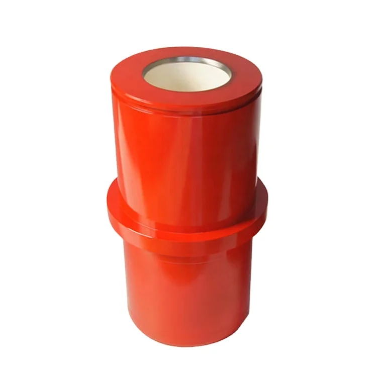
A mud pump liner is basically a heavy wall pipe section with one or two retaining rings at its outer diameter. It is the wear resistance of the inner surface that determines the liner service life. Consequently, the internal surface of the liner is desirably clad with a wear resistant material. The internal cladding layer is subjected to sliding wear by the rubber piston which can wear and cause metallic structure supporting the rubber to contact the liner cladding, thus accelerating the wear process. The cladding material is also subjected to corrosion from the drilling fluid, and metal fatigue caused by cyclic loading, especially at areas where the direction of the piston motion suddenly changes, Further, micro regions of cladding may experience sudden pressurization and depressurization. These operating conditions impose stringent metallurgical requirements on the cladding materials. An ideal cladding material should, therefore, possess high hardness and high resistance to corrosion, impact and metal fatiuge. Such properties are desirably achieved by a uniform, fine grained microstructure, which has been the goal of pump liner makers of many years.
The outer, heavy wall portions of the commercially available mud pump liners typically consist of either a carbon steel, or a low alloy steel; and the liner cladding is, in most cases, a cast sleeve of iron--28% chromium alloy. The sleeve can be centrifugally cast into the steel pipe section or cast separately as a pipe, and shrink fitted into the outer pipe section, then machined to a smooth finish. These manufacturing procedures are lengthy and costly, while providing only a cast metal microstructure which is known to be chemically nonuniform, since in castings the solidification process results in natural segregation of the elemental species contained in the alloy. Furthermore, the cladding thicknesses are kept undesirably large to allow casting processes to be used. The claddings within metallic objects other than pump liners can be similarly characterized and most likely be prone to the same deficiencies.
It is a major object of the invention to provide a powder metal cladding method and apparatus for cladding the internal cavity surface of metal liners and objects, overcoming the above problem and deficiencies. In addition, the invention provides various material combinations for the production of pump liners and internally clad pipe segments for use with oilfield mud pump fluids. There are many other products that can benefit from this processing technique.
As will appear, pressurization of the grain is typically carried out by transmitting force to the grain along a primary axis, the layer extending about that axis and spaced therefrom, whereby force is transmitted by the grain away from the axis and against said layer. To this end, the method contemplates providing a die having a first chamber receiving said object, the die having a second chamber containing grain communicating with grain in the cavity, pressurizing of the grain in the cavity being carried out by pressurizing the grain in the second chamber, as for example by transmitting pressure from the grain in the second chamber to only a medial portion of the grain in the first chamber everywhere spaced from said layer. Further, the metal object is typically cylindrical, the layer being applied on an internal cylindrical surface of said object, the latter for example comprising a mud pump liner.
Referring first to FIG. 1, and alloy steel mud pump liner 10 comprises an elongated tube 11 having an outer flange 12 on one end portion. The tube axis appears at 13, and the tube inner cylindrical surface at 14. Tube 11 may be considered to represent other metal objects having interior surfaces (as at 14) facing internal cavities 15.
Referring to FIG. 2, the next step in the process is to place the liner containing the green now lightly sintered layer 11a within a step die 19 where the liner fits into the large cavity (i.e. first chamber 19) in the die as shown in the figure, and having inner cylindrical walls 19a and 19b. The die second chamber 20 throat diameter D1 should be equal to or smaller than the "green" internal diameter D2 of the mud pump liner 11a. This assures relatively shearless pressing of the green powder metal cladding 11a under largely lateral pressure during the pressurizing step. Chamber 20 has a bore 20a.
As seen in FIG. 3, pressurization takes place in a press 21 after filling both the die and the pump liner cavities with a refractory powder 22 already at a temperature near or above the consolidation temperature of the cladding powder. The pressure from ram 23 is transmitted to the liner by the horizontal forces created within the refractory powder grains. In this regard, the second chamber 20 is in axial alignment with the first chamber 19, the second chamber having a cross section less than the cross section of the first chamber, whereby pressure is transmitted from the grain 22a in the second chamber to only a medial portion of the grain 22b in the first chamber which is everywhere spaced from layer 11a. Therefore, lateral pressurizing of the grain in the cavity 19 is affected by grain pressurized longitudinally in the second chamber, and no destructive shear is transmitted to layer 11a.
The process, while remaining basically the same, may have some variations. For example, there may be an insulating material positioned between the part (the pump liner in FIG. 2) and the die to reduce heat loss before pressing.


 8613371530291