
mud pump liner puller free sample
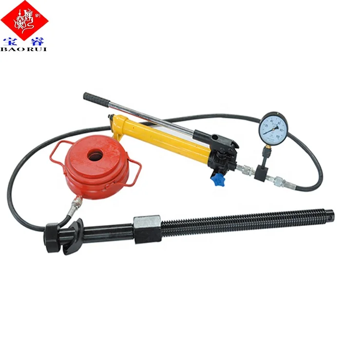
Apex Tool Company strives to manufacture the best liner pullers made in the USA. From redesigning tried and true designs to eliminating weak problematic areas to cutting edge design of new pullers.With Apex Tool Companies liner pullers you will get the job done right the first time.
Drilling consumables such as mud pump systems and their components can drastically increase your uptime while reducing costs and health/safety/environmental (HSE) risks. To support your drilling needs, Forum’s patented P-Quip® mud pump system offers a single-source solution that integrates high-quality fluid end components for maximum longevity and performance.
With more than 20 years of successful operation in severe environments, P-Quip offers a proven track record for the lowest cost of ownership in the industry. As part of our commitment to quality, our mud pump parts use patented Banded Bore™ technology that significantly reduces stress concentrations and leads to longer module life.

3 Fluid end modules and accessories suction and discharge modules Fluid ends manufactured both from carbon steel and stainless steel as alternative material have a very positive impact on the lifecycle costs for triplex pumps operating under difficult conditions. The stainless steel modules have a lifespan that exceeds the general twoyear lifespan associated with carbon steel modules. Consequently, they are economically viable, but are depending on various parameters out of the operating conditions. The suction and discharge valve housings are manufactured from high-strength chrome alloy steel, with carefully worked transitions to ensure favourable fluid flow conditions and to reduce the material strains at critical points. The valve chambers have been designed to comply with the requirements for valve installation according to API specification 7K. Inlet and outlet valve bonnets, and all of the component parts therein, are identical and can be easily interchanged. Valve bonnets incorporate a hydraulically-operated bolt-tensioning system, which permits the rapid and safe removal of internal elements. It is a simple matter to replace the sealing rings since the telescopic-flange assemblies can easily be removed as a pair, without the valve blocks being disturbed. Part numbers for fluid end modules and accessories Discharge module Suction module Discharge module Suction module Fluid end Carbon steel Carbon steel Stainless steel Stainless steel L-type TPK 800 5000 psi 1 10232017 10232016 11027931 11027930 TPK 1000 5000 psi 1 10232017 10232016 11027931 11027930 TPK 1300 5000 psi 2 10230217 10230216 11070565 11070564 TPK 1600 5000 psi 2 10230217 10230216 11070565 11070564 10228500 TPK 1600 7500 psi 10230572 10230571 10230559 10230558 TPK 2000 7500 psi 10230572 10230571 10230559 10230558 TPK 2200 7500 psi 10230572 10230571 10230559 10230558 1 Only suitable for TPK 800 1000 to serial no. 46 2 Only suitable for TPK 1300-1600 from serial no. 47 to serial no. 57
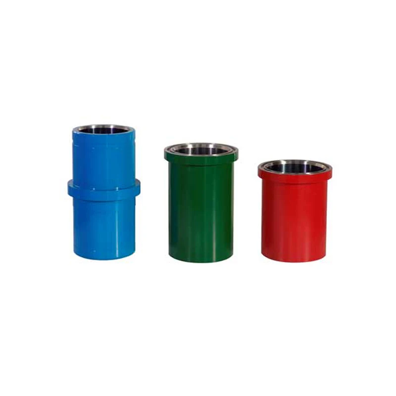
4 We offer fluid end parts and consumables suitable for various types of mud pumps for each individual application. The hydraulic quick release system guarantees low downtimes when replacing fluid end parts, and ensures the highest possible degree of safety (HSE). Liners We offer two types of mud pump liners. They are designed to be highly durable for operating pressures of up to 7 500 psi. Premium chrome liners We offer high chrome-plated liners for the triplex mud pumps. All liners have forged-steel external hulls, which provide resistance to hoop stress, and centrifugally-cast high-chrome sleeves for a greater hardness. A retaining lip at the rear of the liner helps to maintain the internal chrome/iron wear sleeve and protects against the high pressures encountered in today s market applications. Production with computer-controlled machining ensures tighter tolerances and consistent durability and value. The liner is set to match the pressure rating of the pump for each liner size. Premium chrome liners Zirconia liners
5 Zirconia liners Zirconia liners are commonly used with MHWirth TPK series mud pumps. These liners do not produce ID ridges which are common in high-chrome liners. ID ridges are a cause of piston failure. Zirconia sleeves are much harder than chrome sleeves and are also more durable, resulting in reduced rig downtimes and lower ownership costs. The liners are available in sizes ranging from 4 ½ to 7. Regarding its properties, zirconia has three important advantages compared other premium liners: Better impact strength Harder Finer surface The improved wear properties directly results in an extended service life for the sleeve, while the improved impact strength leads to a reduction in the significant costs for the replacement of broken liners in the field. As a consequence of the finer surface finish, there is less friction with the elastomer-metal pump pistons, which in turn ensures an extended piston life and reduced pump-cooling requirements. With a zirconia liner, less maintenance at the pump is required, due to the extended service life achieved for both pistons and liners, consequently leading to a safer environment. Zirconia ceramic liners have been proven to be the most cost-effective liners in use in the industry today. These liners offer the consistent quality needed for reliable pump performance, improved safety, and cost savings. Part numbers for liners and liner gaskets TPK 800 / TPK 1000 Liners (incl. gaskets) Liner gaskets Zirconia Chrome Zirconia Chrome Drawing, Liner size B0000518 A2407641 B0000518 A2407641 4 ½ 11003140 10263641 20263423 20263423 5 11003140 10263642 20263561 21000922 5 ½ 11003139 10263643 20263558 20263561 6 11003138 10263644 20263554 20263558 6 ½ 11003136 10263645 20263555 20263554 7 11003134 10263646 20263588 20263555
6 Part numbers for liners and liner gaskets TPK 1300 Liners (incl. gaskets) Liner gaskets Zirconia Chrome Zirconia Chrome Drawing, Liner size A2407897 B0020825 5 ½ 10263534 20263561 6 10263536 20263558 6 ½ 10263537 20263554 7 10263538 20263555 TPK 1600 1 Liners (incl. gaskets) Liner gaskets Zirconia Chrome Zirconia Chrome Drawing, Liner size B0033030 B0033030 B0033030 5 ½ 11056233 11050064 20263555 20263555 6 11056232 11050065 20263555 20263555 6 ½ 11056231 11050067 20263555 20263555 7 11056230 11050068 20263555 20263555 1 Only suitable up to serial no. 46 Premium chrome liners Zirconia liners
7 TPK 1600 / 2000 ² Liners (incl. gaskets) Liner gaskets Zirconia Chrome Zirconia Chrome Drawing, Liner size B0000615 B0020825 B0000615 B0020825 4 ½ 11051528 11051512 20263561 20263561 5 11051507 11051514 20263561 20263561 5½ 11003520 10263550 20263558 20263561 6 11003519 10263551 20263554 20263558 6 ½ 11003518 10263552 20263555 20263554 7 11003514 10263553 20263588 20263555 7 ½ 10263574 20263588 ² Only suitable for TPK 1600 from serial no. 47 onwards TPK 2200 Liners (incl. gaskets) Liner gaskets Zirconia Chrome Zirconia Chrome Drawing, Liner size B0000614 A2407644 B0000614 A2407644 4 ½ 5 11049656 11049653 20263561 20263561 5 ½ 10263617 10263567 20263558 20263561 6 10263618 10263562 20263554 20263558 6 ½ 10263619 10263563 20263555 20263554 7 10263620 10263564 20263588 20263555 7 ½ 10263568 20263588
8 Pistons Our different types of mud pump pistons are suitable for various applications. Our pistons are designed to deliver maximum performance under almost all drilling conditions. The pistons have sizes ranging from 4 ½ to 7 ½ and are used with all MHWirth mud pump types. They are fully interchangeable with other API-compatible pistons. The most common piston types recommended by us are described below; additional alternatives are available upon request. Standard black piston with guide belt These pistons are designed to resist wear and abrasion in medium service applications involving water-based mud environments. Applications All drilling applications featuring water-based drilling muds Can withstand temperatures of up to 225 F (107 C) Operating pressure ranges from 1 000 psi to 7 500 psi Black compound The piston rubber is made from specially formulated compounds which are resistant to the effects of heat, oil and water. A fabric-reinforced backing of the piston rubbers creates a wear-resistant seal. The hub is formed from a high-grade steel to ensure high tensile strength and a long service life. Seal design This piston uses a guide belt to help direct the piston into the liner while reducing the wear on the piston rubber. With the guide belt, small degrees of misalignment can be compensated for and a proper fit in the liner is ensured. Stingray piston These pistons are designed to resist wear and abrasion in service applications involving high pressures and nonaqueous mud systems. Applications All drilling applications featuring any type of synthetic and oil-based drilling mud (OBM) Can withstand temperatures of up to 212 F (100 C) Operating pressure ranges from 1 000 psi to 7 500 psi One piston per open hole drilling section Stingray compound An improved bull-nose lip design and urethane of the highest quality enable the stingray to significantly outperform the leading competition. Two different urethanes bonded together for superior performance. All urethane pistons require adequate cooling for optimum operation. 30 % more urethane compared to cup lip piston Bonded to hub for increased strength Cut-back hub protects liner Standard black piston with guide belt Stingray piston Stingray HT extreme piston
9 Seal design Designed especially for triplex pumps to maximise performance Constant seal prevents any fluids being squirted by piston Solid lip aids piston alignment in liner Superior abrasion resistance Stingray HT extreme piston These pistons are designed to resist wear and abrasion in service applications involving high temperatures and non-aqueous mud systems. Applications All drilling applications featuring any type of synthetic & oil-based drilling mud (OBM) Can withstand temperatures of up to 300 F (148 C) Operating pressure ranges from 1 000 psi to 7 500 psi One piston per open hole drilling section Stingray HT extreme compound Superior design and high-temperature urethane of the highest quality enable the stingray HT to significantly outperform the leading competition Bonded dual hardness with 45 % more urethane compared to other pistons Special additive to reduce friction between piston and liner. All urethane pistons require adequate cooling for optimum operation. Enhanced chemical degradation resistance Premium urethane compounds with higher tensile strength Seal design Designed especially for triplex pumps to maximise performance Constant seal prevents any fluids being squirted by piston Higher seal area moves piston hub away from liner Seal allows piston to run more concentrically in liner Part numbers for pistons Pistons complete assembly Replacement parts/piston inserts Stingray HT extreme Stingray Standard black with guide belt Standard black Guide belt Drawing, Liner size B0054069 B0015984 B0004476 B0004476 B0004476 B0004496 4 ½ 21051357 21029389 11050894 20261888 21037926 5 21051358 21029385 11050812 20261912 21037840 5 ½ 21051360 21025627 10261990 20261887 21004485 6 21051382 21025628 10261991 20261919 21000915 6 ½ 21051383 21025630 10261992 20261918 21004481 7 21051385 21025631 10261993 20261917 21004927 7 ½ 21051386 21027241 10261994 20261916 21002761
10 Valves MHWirth offers a full range of valves and seats for triplex pumps. There are two different designs for valves and seats which can be selected according to the specific drilling conditions. Full open (FO) valves Full open valves enable uniform fluid end loading, leading to a longer fluid end life. Virtually no warpage due to heat treatment has been encountered because of very small insert extrusion gaps. The axisymmetric shape results in nearly-uniform seat warpage. Serrations in the valve insert groove lock insert in place, thereby reducing swelling of the insert in all environments. The proven design minimises metal-to-metal bearing area between valve and web seat with larger flows involved, increasing valve and seat lives. The newly-developed insert compound has a temperature rating of 300 F (149 C) for the full open HT and 160 F (71 C) for the full open valve. All are designed in accordance with API 7K (styles # 6 and # 8). Cross web (CW) valves The cross web valve is made from carburised premium alloy steel to resist wear, to provide an accurate seal, and to protect against washout or damage to the pump. The original 3-web design allows a maximum flow area through the seat while providing a maximum seating area for the valve. The body consists of a one-piece design that contains the insert to the fullest extent with the minimum use of the material. A patented polyurethane insert is equipped with a double angle (55 ) seal contact surface, which allows cylinder priming to be maintained during pump shutdown. The valves are intended for all drilling operations with pressures of up to 7500 psi and a maximum operating temperature of 300 F (149 C) for the cross web valve HT and 170 F (77 C) for the cross web valve. The large bearing area on the valve seat promotes a long service life. Full open (FO) valve Cross web (CW) valve
12 Tools MHWirth provides a broad range of tools for safe and easy spare parts handling. For your safety: Before any maintenance work is carried out, read the pump safety guidelines thoroughly and apply whenever applicable. Periodically review the information in the safety section with all persons who operate or work on the pumps. WARNING! Loose clothing may be caught in rotating parts, pulling the wearer into the machinery. Refrain from wearing loose clothing and tie back long hair. WARNING! Wear safety harnesses, and ensure safe access is provided to all mud pump items which cannot be reached from floor/deck level. WARNING! Wear appropriate personal protection equipment, safety is of paramount importance. Wear ear protection. The area close to the main drive motors will have noise levels in excess of 80 db(a) when blowers are running. Work on the mud pump may only be performed by physically, mentally and technically competent, duly authorised and certified personnel. Use the permit to work system (PTWS)! The work area must be adequately lit to assure sufficient all round vision. Hydraulic hand pump pressure gauges must be calibrated periodically. Maintain a good housekeeping regime during any service/repair on the mud pumps. Spare parts should always meet the technical requirements specified by the manufacturer. This is ensured when using MHWirth original spare parts. Ensure that adequate and suitable tools and equipment are available to perform all maintenance work.
13 CAUTION! Pump, motors, lubrication oil, pipe work and gearboxes may reach temperatures approaching 60 C during normal operation. Maintenance personnel shall be made aware of this and sufficient cooling off time shall be allowed before commencing work on hot parts. WARNING! Stop and isolate the mud pump from all sources of hydraulic energy and the electrical power supply as per the operator s lock out procedure. The pump must be completely depressurised before attempting any work on the fluid end or piston and liner assemblies. Bursting bladder of pre-charged suction and discharge dampener may cause serious injury to personnel and damage to equipment. Jets and leaks from high pressure oil may be fatal. Ensure the system is switched off, depressurised and locked out before any work is performed on the mud pump. Safety instructions for HP hose as part of tool package High pressure hoses require special safety precautions and instructions for use! Do not kink or bend the hose below the specified minimum bending radius. The specified minimum bending radius is valid for static applications; for dynamic applications we advise that the minimum bending radius should be doubled. Do not subject the hose to any twisting or torsion stress. Do not use the hoses as traction components for lifting or dragging other equipment. Use only adaptors and reduction pieces which have been approved by RK Kutting. The lines must be inspected at regular intervals. Before each installation, the hoses must be inspected for damage, kinks, wear, corrosion, cracks and other kinds of damage. It is absolutely essential to replace damaged hoses immediately. Use only hoses with a known working pressure. To extend the service life of the hose, use only clean media. If a malfunction is suspected, immediately shut down the product or machine in which thehose is installed andreplace the hose. The maximum permitted operating pressure is determined by the weakest element in the installation.
14 Listing of standard mud pump tool package Picture Description Part no Fig 10 1 Liner puller 11002584 Fig 11 1 Valve cover puller 11012412 Fig 12 1 High pressure hydraulic pump 10234283 All tools in our standard tool package are supplied in an aluminium box, except the piston assembly tool which is mounted to the pump frame local to the fluid end. 1 The size of the aluminium box is: L x W x H 1 200 mm x 800 mm x 500 mm Fig 13 1 Hydraulic tool for suction valve housing 11002814 Fig 14 1 Charge hose for suction dampener 10234311 Fig 15 1 Wrench for liner clamping 10267556 Fig 16 1 Socket wrench for valve closure 10234304 Fig 17 1 Torque bar 11002706 Fig 18 1 Discharge strainer removal bar 1 10234293 Fig 19 1 Torque bar 10234289 Fig 20 1 Wear ring pulling device 11004045 Fig 21 1 Chain tensioning tool 2 11030324 Fig 22 1 Pressure intensifier 1 10234285 Fig 23 1 Piston assembly tool 1 11019861 1 Only for TPK 2200 2 Only for chain-driven pumps The liner puller shall not be used for lifting Fig 10: liner puller Part no: 11002584 Used for pulling the cylinder liners clear of the fluid end. Fig 11: valve cover puller Part no: 11012412 Used for removing the valve covers on the discharge valve housing and the suction valve housings.
15 Fig 12: hydraulic pump Part no: 10234283 The hand pump is used to pressurise the various stud tensioning devices used during regular maintenance and for expelling the valve seat. It is also used to break the taper lock on some bearings. Fig 13: hydraulic tool for suction valve housing Part no: 11002814 Four hydraulic tensioning nuts and one hydraulic manifold is used to tension the studs that fasten the suction valve housing to the discharge valve housing. The charge hose is only the connecting piece between the suction dampener and the pressure regulator/bleed valve at the nitrogen bottle (NB. connector to the nitrogen bottle is not scope of supply). Fig 14: charge hose for suction dampener Part no: 10234311 This is used to connect the suction dampener to the nitrogen supply, which is used to charge the bladder. Fig 15: wrench for liner clamping Part no: 10267556 This is used to tighten the jacking nuts as part of the hydraulic bolt tensioning procedure, used for installation and removal of the cylinder liners. Fig 16: socket wrench for valve closure Part no: 10234304 This is used to turn the jacking screw as part of the hydraulic bolt tensioning procedure, used for installation and removal of the discharge and suction valve closures. The torque bar (part no: 11002706) from the standard tools set is used in conjunction with this tool. Fig 17: torque bar Part no: 11002706 This is used in conjunction with the socket wrench for valve closure drawing (part no: 10234304), and used in conjunction with driveshaft turning in order to turn the driveshaft by hand during maintenance procedures.
16 Fig 18: discharge strainer removal bar Part no: 10234293 Used to loosen or tighten the threaded closure ring of the discharge strainer, to be used on 7 500 psi rated fluid ends. Fig 19: torque bar Part no: 10234289 Used in conjunction with the hydraulic tools for suction valve housing, to nip tight the base nuts (part no: 11002814) Fig 20: wear ring pulling device Part no: 11004045 Used for pulling the wear rings. Fig 21: chain tensioning tool Part no: 11030324 Used to tension/de-tension the chain. Fig 22: pressure intensifier Part no: 10234285 The pressure intensifier is used in conjunction with the hydraulic pump. It increases the pressure output of the pump threefold to 3 000 bar (43 500 psi). It is used to expel the valve seats in the discharge valve housings and the suction valve housings. Fig 23: Piston assembly tool Part no: 11019861 The piston assembly tool is used to install and de-install the piston on the piston rod.
17 Listing of special mud pump tool package Picture Description Part no Fig 24 1 Special wear ring pulling device 11004321 Fig 25 1 Manual valve seat puller cross web 11023700 The special tools will reduce human work-load during regular standard maintenance activities and can be ordered upon request. Fig 26 1 Manual valve seat puller full open 11051795 Fig 27 1 Air operated wrench type 21027571 Fig 28 1 Hydraulic power pack unit 21040609 Fig 29 1 Filling & Flushing unit 21059454 Fig 24: special wear ring pulling device Part no: 11004321 To be used as an alternative to pull the wear rings, see fig 20. Fig 25: manual valve seat puller for cross web seats Part no: 11023700 Fig 26: manual valve seat puller for full open seats Part no: 11051795
18 Fig 27: air operated wrench type CLS 315 Part no: 21027571 Power supply: Compressed air 4 7 bar, (58 101.5 psi) Torque: 1 180 to 3 460 Nm Impact size: SW 65 Weight approximately: 9 kg To be used as an alternative to turning the mud pump by hand. Fig 28: hydraulic power pack unit LHP 2 500 Part no: 21040609 Operating pressure: max. 2 500 bar/36 250 psi Power supply: Compressed air 6 10 bar, (87 145 psi) Dimension: 400 x 350 x 550 mm (L x W x H) Weight approximately: 35 kg To be used as an alternative to the hand lever pump, see fig 11. Details concerning your spare parts order at a glance We want to make the process of ordering spare parts as simple as possible for you. Simply choose the type and size of your MHWirth mud pump from the table below and order the corresponding spare parts (using the part numbers) at www.mydrilling.com. If you need additional information or have further questions, please contact your local Service Account Manager. Fig. 29: Filling & Flushing Unit - BS 25-CL Part no. 21059454 Operating pressure: max. 5 bar Flow rate: 25 l/min Power supply: Compressed air 6 max. 8,4 bar Weight approximately: 170 kg
19 Quick reference guide Wear parts for TPK 800 & 1000 5000 psi Liners incl. gaskets Liner gaskets Pistons complete assembly Zirconia Chrome Zirconia Chrome Stingray HT extreme Stingray Standard black with guide belt Drawing Liner size B0000518 A2407641 B0000518 A2407641 B0054069 B0015984 B0004476 4 ½ 11046140 10263641 20263423 20263423 21051357 21029389 11050894 5 11003140 10263642 20263561 21000922 21051358 21029385 11050812 5 ½ 11003139 10263643 20263558 20263561 21051360 21025627 10261990 6 11003138 10263644 20263554 20263558 21051382 21025628 10261991 6 ½ 11003136 10263645 20263555 20263554 21051383 21025630 10261992 7 11003134 10263646 20263588 20263555 21051385 21025631 10261993 Replacement parts / piston inserts Valve parts Standard black Guide belt Full open Cross web Drawing Liner size B0004476 B0004476 B0004496 4 ½ 20261888 21037926 5 20261912 21037840 5 ½ 20261887 21004485 6 20261919 21000915 6 ½ 20261918 21004481 7 20261917 21004927 Drawing Style B0025089 Valve API style # 6 11041389 Valve cone 21032294 1 Spring 20260707 Valve seat 21032293 Guide bushing 20228205 O-ring 21004390 2 O-ring 21004391 1 Including valve plate 2 Included in valve seat Fluid end modules & accessories Discharge module Suction module Discharge module stainless steel Suction module stainless steel Wear ring Gasket for wear ring Gasket for valve cover 10230217 10230216 11027931 11027930 10232018 20232027 20232028 Tools/seat puller assemblies Full open Cross web Premium Standard Note Mechanical valve seat puller API style # 6 Hydraulic valve seat puller API style # 6 Wear ring puller 11004321 11031722 21032541 3 Liner puller 11041842 Suitable from serial no. 17 upwards 3 Only for pumps which are equipped with hydraulic quick release system
20 Wear parts for TPK 1300 5000 psi Liners incl. gaskets Liner gaskets Pistons complete assembly Zirconia Chrome Zirconia Chrome Stingray HT extreme Stingray Standard black with guide belt Drawing Liner size A2407897 B0020825 B0054069 B0015984 B0004476 5 ½ 10263534 20263561 21051360 21025627 10261990 6 10263536 20263558 21051382 21025628 10261991 6 ½ 10263537 20263554 21051383 21025630 10261992 7 10263538 20263555 21051385 21025631 10261993 Replacement parts / piston inserts Valve parts Standard black Guide belt Full open Full open HT Cross web Cross web HT Drawing Liner size B0004476 B0004476 B0004496 5 ½ 20261887 21004485 6 20261919 21000915 6 ½ 20261918 21004481 7 20261917 21004927 Drawing Style B0024715 B0075364 A2407149 A2407149 Valve assy 11095570 11108705 10260811 11110971 Valve cone 21030726 21051412 20260813 21079955 Spring 20260794 20260794 20260815 20260815 Valve seat 11095891 11095891 20260812 20260812 Guide bushing - - - - O-ring 21006661 21006661 21006661 21006661 Valve plate - - 20260814 21079951 Fluid end modules & accessories Discharge module Suction module Discharge module stainless steel Suction module stainless steel Wear ring Gasket for wear ring Gasket for valve cover 10230217 10230216 11070565 11070564 10230244 20230445 20228419 Tools/seat puller assemblies Full open Cross web Premium Standard Note Mechanical valve seat puller API style # 8 Hydraulic valve seat puller API style # 8 11051795 11023700 Wear ring puller 11004321 11031722 10234283 3 10234283 3 Liner puller 10267285 suitable from serial no. 17 upwards Amplifier for hydraulic puller 10234285 10234285 3 Only for pumps which are equipped with hydraulic quick release system
21 Wear parts for TPK 1600 5000 psi Liners incl. gaskets Liner gaskets Pistons complete assembly Zirconia Chrome Zirconia Chrome Stingray HT extreme Stingray Standard black with guide belt Drawing Liner size B0033030 B0033030 B0033030 B0054069 B0015984 B0004476 5 ½ 11056233 11050064 20263555 20263555 21051360 21025627 10261990 6 11056232 11050065 20263555 20263555 21051382 21025628 10261991 6 ½ 11056231 11050067 20263555 20263555 21051383 21025630 10261992 7 11056230 11050068 20263555 20263555 21051385 21025631 10261993 Replacement parts / piston inserts Valve parts Standard black Guide belt Full open Full open HT Cross web Cross web HT Drawing Liner size B0004476 B0004476 B0004496 5 ½ 20261887 21004485 6 20261919 21000915 6 ½ 20261918 21004481 7 20261917 21004927 Drawing Style B0024715 B0075364 A2407149 A2407149 Valve assy 11095570 11108705 10260811 11110971 Valve cone 21030726 21051412 20260813 21079955 Spring 20260794 20260794 20260815 20260815 Valve seat 11095891 11095891 20260812 20260812 Guide bushing - - - - O-ring 21006661 21006661 21006661 21006661 Valve plate - - 20260814 21079951 Fluid end modules & accessories Discharge module Suction module Discharge module stainless steel Suction module stainless steel Fluid end L-type Wear ring Gasket for wear ring Gasket for valve cover 10230217 4 10230216 4 11070565 11070564 10228500 10230244 20230445 20228419 Tools/seat puller assemblies Full open Cross web Premium Standard Note Mechanical valve seat puller API style # 8 Hydraulic valve seat puller API style # 8 11051795 11023700 Wear ring puller 11031722 10234283 3 10234283 3 Liner puller Amplifier for hydraulic puller 10234285 10234285 3 Only for pumps which are equipped with hydraulic quick release system 4 Only for modification kit
22 Wear parts for TPK 1600 / 2000 7500 psi Liners incl. gaskets Liner gaskets Pistons complete assembly Zirconia Chrome Zirconia Chrome Stingray HT extreme Stingray Standard black with guide belt Drawing Liner size B0000615 B0020825 B0000615 B0020825 B0054069 B0015984 B0004476 4 ½ 1 11051528 11051512 20263561 20263561 21051357 21029389 11050894 5 1 11051507 11051514 20263561 20263561 21051358 21029385 11050812 5 ¼ 2 11003524 10263573 20263561 20263561 21051359 21035606 11010112 5 ½ 11003520 10263550 20263558 20263561 21051360 21025627 10261990 6 11003519 10263551 20263554 20263558 21051382 21025628 10261991 6 ½ 11003518 10263552 20263555 20263554 21051383 21025630 10261992 7 11003514 10263553 20263588 20263555 21051385 21025631 10261993 7 ½ 10263574 20263588 21051386 21027241 10261994 Replacement parts / piston inserts Standard black Guide belt Drawing Liner size B0004476 B0004476 B0004496 4 ½ 1 20261888 21037926 5 1 20261912 21037840 5 ¼ 2 20261920 21006682 5 ½ 20261887 21004485 6 20261919 21000915 6 ½ 20261918 21004481 7 20261917 21004927 7 ½ 20261916 21002761 1 Only for 1600 HP 7500 psi type 2 Only for 2000 HP Valve parts Full open Full open HT Cross web Cross web HT Drawing Style B0024715 B0075364 A2407149 A2407149 Valve assy 11095570 11108705 10260811 11110971 Valve cone 21030726 21051412 20260813 21079955 Spring 20260794 20260794 20260815 20260815 Valve seat 11095891 11095891 20260812 20260812 Guide bushing - - - - O-ring 21006661 21006661 21006661 21006661 Valve plate - - 20260814 21079951 Fluid end modules & accessories Discharge module Suction module Discharge module stainless steel Suction module stainless steel Wear ring Gasket for wear ring Gasket for valve cover 10230572 10230571 10230559 10230558 10230224 20230218 20228419 Tools/seat puller assemblies Full open Cross web Premium Standard Note Mechanical valve seat puller API style # 8 Hydraulic valve seat puller API style # 8 11051795 11023700 Wear ring puller 11004321 11004045 10234283 5 10234283 5 Liner puller 10267285 TPK 1600 suitable from serial no. 47 up to serial no. 57 TPK 2000 suitable up to serial no. 21 Amplifier for hydraulic puller 10234285 10234285 Liner puller 11002584 TPK 1600 suitable from serial no. 58 upwards TPK 2000 suitable from serial no. 58 upwards 5 Only for p umps which are equipped with hydraulic quick release system
23 Wear parts for TPK 2200 7500 psi Liners incl. gaskets Liner gaskets Pistons complete assembly Zirconia Chrome Zirconia Chrome Stingray HT extreme Stingray Standard black with guide belt Drawing Liner size B0000614 A2407644 B0000614 A2407644 B0054069 B0015984 B0004476 5 11049656 11049653 20263561 20263561 21051358 21029385 11050812 5 ½ 10263617 10263567 20263558 20263561 21051360 21025627 10261990 6 10263618 10263562 20263554 20263558 21051382 21025628 10261991 6 ½ 10263619 10263563 20263555 20263554 21051383 21025630 10261992 7 10263620 10263564 20263588 20263555 21051385 21025631 10261993 7 ½ - 10263568-20263588 21051386 21027241 10261994 Replacement parts / piston inserts Standard black Guide belt Drawing Liner size B0004476 B0004476 B0004496 5 20261912 21037840 5 ½ 20261887 21004485 6 20261919 21000915 6 ½ 20261918 21004481 7 20261917 21004927 7 ½ 20261916 21002761 Valve parts Full open Full open HT Cross web Cross web HT Drawing Style B0024715 B0075364 A2407149 A2407149 Valve assy 11095570 11108705 10260811 11110971 Valve cone 21030726 21051412 20260813 21079955 Spring 20260794 20260794 20260815 20260815 Valve seat 11095891 11095891 20260812 20260812 Guide bushing - - - - O-ring 21006661 21006661 21006661 21006661 Valve plate - - 20260814 21079951 Fluid end modules & accessories Discharge module Suction module Discharge module stainless steel Suction module stainless steel Wear ring Gasket for wear ring Gasket for valve cover 10230572 10230571 10230559 10230558 10230224 20230218 20228419 Tools/seat puller assemblies Full open Cross web Premium Standard Note Mechanical valve seat puller API style # 8 Hydraulic valve seat puller API style # 8 11051795 11023700 Wear ring puller 11004321 11004045 10234283 3 10234283 3 Liner puller 10234300 Amplifier for hydraulic puller 10234285 10234285 3 Only for pumps which are equipped with hydraulic quick release system
NOV 12-P-160 Mud Pump is rated at 1600 input horsepower (1193 kw) at 120 strokes per minute, with a 12-inch (304.8 mm) stroke. Multiple liner sizes allow pressures and volumes to handle circulation requirements in deep drilling applications.
Flexibility: Compact engineering provides higher efficiency in less space. The NOV 12-P-160 Triplex Mud Pump light weight and flexible design make it easily adaptable to a variety of rig configurations. This provides flexibility as drilling requirements and conditions change.
Fluid End Modules: NOV offers a choice of fluid end modules and valve covers for every P Series pump model to select the fluid end module that exactly matches drilling requirements. All pump models can be equipped with either the standard or premium forged, two-piece interchangeable fluid modules

abstractNote = {Failure of a liner seal is one of the more critical failures on a mud pump because this seal interfaces with the pump body. Therefore, failures, usually damage the pump body, leading to repair or replacement of the fluid end itself. One of the more common liner seal problems involves counter-bore-type seals. This type of seal is easily affected by two aspects of the problem that are found in the mud pump fluid end-wear and foreign matter in the seal groove. Factors relative to difficult liner removal are discussed. Piston damage, careless seal installation and corrosion damage are also examined.},

Whether onshore or offshore, well drilling sites rely on a multitude of systems to successfully perform the drilling operation. The mud pump is a key component tasked with circulating drilling fluid under high pressure downhole. The mud pump can be divided into two key sections: the power end or crosshead and the fluid end. Proper alignment of the pump’s crosshead to the fluid end liner is necessary to maximizing piston and liner life. Misalignment contributes to
accelerated wear on both the piston and the liner, and replacing these components requires downtime of the pump. Traditional methods of inspecting alignment range from using uncalibrated wooden rods, Faro Arms and micrometers to check the vertical and horizontal alignment of the piston rod OD to the piston liner ID. These are time consuming and cumbersome techniques that are ultimately not well suited to troubleshoot and solve alignment issues.
A “Mud Pump Laser Alignment Kit” enables you to measure where the piston will run through the liner at various positions along the pump’s stroke. It will also project a laser centerline from the fluid end back towards the rear power end of the pump that can be used to determine how much shimming is required to correct any alignment issues. The kit can include either a 2-Axis receiver or a 4-Axis which accepts the laser beam and documents where it falls on the active surface of the receiver. The 4-Axis receiver can decrease alignment time by as much as 50% as it will measure angularity as well as X and Y while the 2-Axis does not and will need multiple measurement locations to get the same information. In addition, the alignment system is a non-intrusive service requiring the removal of only the piston rod which allows for much quicker service and less down time on the pump. As the mud pumps in question are located globally both on and offshore, having a small, portable system is another great advantage. Our recommendation would be Pinpoint laser System’s “Mud Pump Alignment Kit”. They are being used by many of the leading repair service companies and have been their main alignment tool for over 15 years. Manufacturers are also utilizing these for new pump set-up.


 8613371530291