
mud pump midland free sample
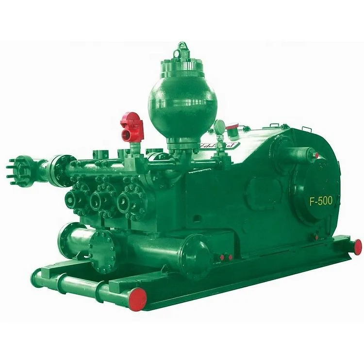
The 2,200-hp mud pump for offshore applications is a single-acting reciprocating triplex mud pump designed for high fluid flow rates, even at low operating speeds, and with a long stroke design. These features reduce the number of load reversals in critical components and increase the life of fluid end parts.
The pump’s critical components are strategically placed to make maintenance and inspection far easier and safer. The two-piece, quick-release piston rod lets you remove the piston without disturbing the liner, minimizing downtime when you’re replacing fluid parts.

Created specifically for drilling equipment inspectors and others in the oil and gas industry, the Oil Rig Mud Pump Inspection app allows you to easily document the status and safety of your oil rigs using just a mobile device. Quickly resolve any damage or needed maintenance with photos and GPS locations and sync to the cloud for easy access. The app is completely customizable to fit your inspection needs and works even without an internet signal.Try Template

Aug. 16, 1955 J. E. BLISS ET AL DEGASSING 0F DRILLING MUD Filed Oct. 50, 1951 VACUUM PUMP " WATER 53 SUPPLY 1 23 w 20 HEATING 22 1 $2 CO|L- I 15 FIG. 3
INVENTORS J.E. BLISS A.J. JOSEPH BYHWJQMq A T TORNEKS United States Patent Oflice Ziflifdflfih Patented Aug. 1d, 1955 DEGASSING or DRILLING MUD Jack E. Bliss and Arthur J. .loseph, Midland, Tex., as-
It is well known practice in oil and gas drilling to inspect and examine the mud fluid returns from a well in order to determine the nature of the strata being traversed by the drill, and also the character of the fluid contents, if any, of such strata. Such procedure is of considerable importance because direct evidence of oil and gas has always been and still is the most dependable criterion of a commercial productive well.
in the drilling of oil and gas wells by the rotary method, it is customary to circulate a mud laden fluid down through the drill pipe and out openings in the bottom thereof. This mud laden fluid exerts cooling and lubricating effects on the drill and also picks up and suspends cuttings formed by the action of said drill. This mud, together with the cuttings suspended therein, is returned to the surface through the annular space between the drill pipe and the wall of the bore hole or casing, if casing has been set. At the surface the stream of mud fluid is passed over a shale shaker in order to separate the coarser cuttings from the drill fluid. The fluid in turn passes into a mud pit from which it is recirculated by pumps back through the drill pipe. in the specification to follow, the term occluded is used to describe the condition of retention of the hydrocarbons in the earth sample whether such formof retention be absorption, adsorption, or merely structural envelopment. In order to make use of the occluded gas as an index of the formations traversed by the drill, it is of course necessary to extract said gas from the drilling mud.
Because it is common practice to maintain the drilling mud at a specific gravity such that the hydrostatic head of drilling fluid at the bottom of the hole is greater than any fluid pressure encountered in the formations traversed during the drilling operations, there is very little, if any, flow of fluid from the formation into the drilling fluid. Therefore, the amounts of gases or other hydrocarbons mixed with the drilling fluid from the formations traversed by the drill are usually small thereby resulting in their detection at the surface being accompanied by many difficulties. Since the volume content of combustible gas in drilling mud ranges from negligible amounts up to only several per cent, considerable difliculty has been experienced in the past in providing apparatus capable of separating the gases picked up by said drilling fluid from said fluid for purposes of analysis.
This invention is concerned primarily with those situations in which the gas content of the mud is too small to be noticeable by visual inspection, although there is nothing in the application of the apparatus herein provided which would prevent its use in upper ranges. For example, the routine testing of mud in high pressure areas can be provided to detect dangerous rises in gas concentration which might, if allowed to go uncontrolled, result in a blow out. It is in the range of lower concentrations, however, that the greatest benefits are derived from the analyzer of the present invention because of the difficulty of obtaining direct evidence of oil and gas by any method except the analysis of drilling mud.
The general analytical procedure followed in the removal of this gas from the drilling mud in accordance with this invention comprises pumping mud from either the discharge or suction lines on the rig through a supply line to the field laboratory, by passing a definite volume of mud into the extraction unit, heating the mud in a closed reservoir to an elevated temperature and pressure, flashing the heated content to a water-cooled evacuated chamber, diluting the extracted gas with hydrocarbon-free air to restore the pressure to atmospheric, forcing the diluted gas mixture out of the extraction apparatus through suitable drying tubes into the analytical apparatus by the use of water, and, finally, measuring the combustible content of the mixture by an electrical method.
It is an object of the present invention to provide improved apparatus for extracting occluded gases from drilling mud and testing said gases for combustible content.
Referring now to the drawing in detail and to Figure 1 in particular, there is illustrated mud separating and analyzing equipment wherein mud from the discharge pipe on the rig enters the intake of pump 10 through the conduit 11 containing an intake valve 12. The mud is directed from pump 10 through a conduit 13 from which a test sample is obtained by opening valves 14 and 15, and partially closing valve 16, thereby causing a portion of the mud stream in conduit 33 to by-pass through the pressure reservoir 17 until it overflows through conduit 18 to drain 20.
The sample comprising a known volume of mud then is isolated in pressure reservoir 17 by closing all of the valves leading to said reservoir. Following this, reservoir 17 is heated by means of an electrical heating coil 21 which is supplied by a source of heating current 22 applied thereto by the closure of switching means 23. To improve the heating conditions a jacket of thermal insulation 24 is provided surrounding reservoir 17. The pressure within reservoir 17 is registered both upon a gage 25 and pressure responsive electrical switch 26, the latter being described in greater detail in conjunction with Figure 2. Heating current is applied to coil 21 until the pressure within reservoir 17 reaches some predetermined value, preferably between 30 and 55 pounds gage which corresponds to a temperature range of approximately to C. Such a temperature is high enough to be effective in driving off the occluded gases and yet low enough to avoid thermal cracking of any oil which may be present. At this preselected pressure, switch 26, which is adjusted to be responsive to said pressure, serves to open valve 27 by means of control device 28 in outlet conduit 29 so as to connect reservoir 17 with a second chamber 38*, which can be either at approximately atmospheric pressure or less, as may be desired. Pump 337i acting through valve 32, conduit 33, and valve 34: serves to evacuate chamber to the desired degree of vacuum which is read from pressure gage 35 communicating with chamber 36. At the same time valve 27 is opened, switching means 23 in the heating coil circuit simultaneously is opened by control means 36 thereby removing the heating current supplied to reservoir 17. Control means 36 also is regulated by pressure responsive switch 26 as described in greater detail hereinafter.
The rush of steam and mud into evacuated chamber 30 carries a large amount of heat which is dissipated rapidly by water circulating in a copper coil 37 surrounding chamber 3% and soldered thereto to make good thermal contact. Vacuum chamber 3t preferably has a volume several times as large as the heated reservoir 1"7 and should be located above it in order that mud and water can run back after the first rush has subsided and the steam condensed.
It should thus be apparent that the foregoing procedure fulfills the three essential requirements for and thorough extraction of occluded gases from the mud: high temperature, agitation, and vacuum. The next step in the analysis procedure is to raise the pressure within vacuum chamber 3% to atmospheric in order that the gaseous mixture can be transferred. conveniently to the analytical unit. This is accomplished by admitting hydrocarbon free air as may be necessary from cylinder 48 through valves 41 and The admission of said air results in a dilution of the gas sample, but this is not important since the analytical method possesses ample sensitivity to measure the combustible content thereof even after dilution. Since the volume of gas extracted from the mud is negligible as compared to the total volume of vacuum chamber 3%, the dilution factor is essentially constant for all samples.
In order to analyze this gaseous sample the gas-air mixture is forced out from vacuum chamber 39 through drying reagents contained in tube 42, and into the combustion unit 43 of an electrical analyzer. This transfer is accomplished either by admitting water through valve 45 into chamber 30 or by an air pump, not shown. To indicate the water level within chamber 38 as the gas is being forced out therefrom, a glass gage 46 is provided which is connected to said chamber by means of suitable packing glands, not shown. The danger of accidentally overflowing chamber 30 by failure of the operator to turn off the water flow at the proper time is eliminated by means of a float 47 in the top of chamber 3 which closes valve 45 before the water rises high enough to do any damage.
In addition to the equipment above described, facilities are provided for washing out the mud after analysis and for testing both reservoir 17 and vacuum chamber 30 for leaks which may occur therein. Once the test of a given sample is completed, valve 14 at the bottom of reservoir 17 is opened as is valve 48 connecting chamber 30 with reservoir 17, and the mud and water mixture from both chambers is flushed out by means of air pressure applied through conduit 31 A water jet 59 in reservoir 17 is connected to the main water supply through valve 51 and thereby aids in sweeping out any especially heavy or viscous muds contained within reservoir 17. High pressure air may be admitted through valve 52 for the purpose of testing for leaks. As an emergency measure a receptacle 53 is provided at the top of the pressure reservoir 17 and connecting there with through valve 5-4 so that mud samples may be poured downwardly into reservoir 17 from said receptacle 53 in case the mud pump lit? should fail in operation.
The percentage of the gas occluded Within the mud is calculated in terms of a standardizing gas (either propane or butane) used in calibrating the electrical analyzer unit. The comparison samples are obtained by admitting into tank 57, which previously is evacuated, a measured quantity of gas from container 5%, reduced in pressure at valve 559 to atmospheric, and measured within calibration chamber 69. This hydrocarbon gas in calibration chamber se is swept into the storage tank 57 by air from compressed air source 4d being applied through valves 6i and 59, thereby forming a synthetic combustion gas-air mixture of known proportions within storage tank 57. This synthetic mixture alternately can be analyzed by unit 43 to serve as a comparison standard.
In Figure 3 the operation of control units 28 and 36 in response to pressure actuated switch 26 is shown in detail. After the mud sample has been pumped into reservoir 17, switch is closed manually to connect voltage source 22 with heating coil 21. This completed circuit is formed in part through the armature 101 of relay 102. Armature 101 is maintained at its normally open position by means of a suitable tension spring 103. At this time valve 27 is in a closed position. Valve 27, which is a conventional solenoid operated valve, contains a plunger 105 which rests within valve seat 106 in its normally closed position, said plunger 105 being constrained in this position by means of a compression spring 168. Relay winding lit) and solenoid winding 111 are connected in series arrangement with a source of voltage 112 and mercury switch 80 of pressure actuated switch 26. At the instant the first preselected pressure is reached in reservoir 17 mercury switch 80 is tipped to complete the electrical circuit through windings 110 and 111 and voltage source 112. This in turn serves to close armature 101 of relay 102, thereby breaking the circuit to heating coil 21. At the same time, solenoid switch 28 is operated to open valve 27 so as to pass the heated vapors from reservoir 17 into vacuum chamber 30. Once the pressure within reservoir 17 falls to the second lower preselected value, mercury switch 80 again is tipped to open the electrical circuit through windings 110, 111 and voltage source 112. This in turn removes the electrical current from winding 111 which once again closes valve 27. Heating current through coil 21, however, is not restored due to the action of catch arm 114 mounted on armature 102 which holds armature 101 closed. Relay 102 must be reset manually before a second sample is analyzed.
From the foregoing description it should thus be apparent that there has been provided in accordance with this invention an improved form of mud analyzer which effectively serves to liberate any gases occluded within the mud sample under consideration. In this regard means have been provided to automatically transmit the gases driven off said mud sample under preselected conditions and to pass said gases into an accompanying analysis chamber. While this invention has been described in conjunction with a present preferred embodiment thereof, it should be apparent to those skilled in the art that various modifications can be made Without departing from the scope of this invention. This is particularly true with regard to the electrical connections in Figure 3. in parallel with voltage source 112,, for example, in place of the series connections shown. It is, therefore, our intention not to be limited to the precise embodiment herein described.

Why APPI:Drilling mud is hard on pumps as it’s both viscous and caustic. For manufacturers, this means it needs to be quick and easy to access pumps that require repair or replacement.
When Brandon Westenberg, owner of Portable Mud Systems, specified a pump for one of his mud systems he matched it with one of our HF4700 AC electric mud pump hoists with an optional strap to do the lifting.
It is mounted on a beam that goes over the pump and has epoxy based paint with stainless steel fasteners to help protect it from the elements – including the mud being slung on the jobsite.

I’ve run into several instances of insufficient suction stabilization on rigs where a “standpipe” is installed off the suction manifold. The thought behind this design was to create a gas-over-fluid column for the reciprocating pump and eliminate cavitation.
When the standpipe is installed on the suction manifold’s deadhead side, there’s little opportunity to get fluid into all the cylinders to prevent cavitation. Also, the reciprocating pump and charge pump are not isolated.
The suction stabilizer’s compressible feature is designed to absorb the negative energies and promote smooth fluid flow. As a result, pump isolation is achieved between the charge pump and the reciprocating pump.
The isolation eliminates pump chatter, and because the reciprocating pump’s negative energies never reach the charge pump, the pump’s expendable life is extended.
Investing in suction stabilizers will ensure your pumps operate consistently and efficiently. They can also prevent most challenges related to pressure surges or pulsations in the most difficult piping environments.


 8613371530291