
mud pump motor thermal imaging factory

Mud pump, refers to the drilling process to the drilling mud or water and other washing liquid machinery. The main components are volute, impeller, pump seat, pump case, support cylinder, motor seat, motor and other components. Impeller nut is cast iron, so corrosion resistance is good, and convenient processing technology. Pump seat is equipped with four skeleton oil seal and shaft sleeve, prevent shaft wear, prolong the service life of the shaft.
ATO offers high quality vertical mud pumps with thick, solid shaft and copper motor. Various models are available, such as 2 inch mud pump, 3 inch mud pump, 4 inch mud pump and 6 inch mud pump.
Vertical mud pump is used as suction and pouring of river mud, suitable for oil refining, construction, printing and dyeing, chemical industry and other industries.

Check the suction and case drain lines of the pump by recording the temperatures at points “A” and “B” in Figure 1. The oil in the “A” line should be very near the oil temperature in the reservoir. The oil that flows out of the case drain line (B), is the oil that bypasses the internal components inside the pump. Most piston pumps bypass 1-3 percent of the maximum pump volume. Vane pumps may bypass as much as 5 percent of the maximum rated volume. For a 30-gallon-per-minute piston pump, the amount of oil in this line should be one-third (1 gallon per minute). Because the oil does no useful work, heat will be generated as the oil bypasses the internal pistons. This line, of course, will be hotter than the oil entering the pump through the suction line.
The suction and case drain temperatures are shown in Figure 2. The oil entering the pump is 126 degrees F, while the oil in the case drain is 135 degrees F. As the pump wears, the bypassing will increase, causing an increase in temperature of the case drain line. If the pump is checked a month later and the temperature in the case drain is 145 degrees F, then the pump has worn considerably. The flow rate should then be checked by installing a flow meter in the line. If the flow rate reaches or exceeds 10 percent of the maximum pump volume, the pump should be replaced.
In the previous example, a flow rate of 3 gallons per minute (GPM) would indicate a badly worn pump. Since the amount of case drain flow can vary from one pump manufacturer to another, the key is to make initial temperature checks when the pump is relatively new to establish a reference. Permanent installation of a flow meter in the case drain line is also recommended.
Check the tank line temperature of the air bleed valve at point “C” in Figure 1. The purpose of the air bleed valve is to automatically bleed air out of the line when the pump is first started. These valves are most commonly found on systems where the pump is mounted above the oil level. Once the air is bled out and the hydraulic pressure builds to the spring setting (approximately 12 pounds per square inch), the valve will shift closed. The valve is relatively small and can only handle a flow rate of 2 GPM. In most systems, the pump volume is higher than 2 GPM. Although the full pump volume usually cannot flow through the valve, heat will be generated if the valve fails open. This can increase the oil temperature as well as cause the actuators to move slower, particularly if a low-volume pump is used.
Check the tank line temperature of the relief valve (RV) at point “D” in Figure 1. In a system where a pressure-compensating pump is used, the relief valve spring should be set 250-300 pounds per square inch (PSI) above the compensator setting. The purpose of the relief valve is to provide a flow path in the event the compensator spool fails to shift and reduce the pump volume to a near 0 GPM output. The tank line of the relief valve should be at ambient temperature.
In Figure 4, the tank line is 99.7 degrees F, well below the oil temperature in the reservoir. If this line is hot, then the pump compensator spool has failed to shift, the relief valve is stuck partially open or the plant knob-turner has increased the compensator setting above the relief valve setting.
Check the temperature at the top (K) and bottom (L) of the accumulator shell. The bottom half of the accumulator should be warmer than the top half. The heat is generated by the friction of the oil as it flows in and out of the shell. On a bladder type of accumulator, the rubber bladder will be compressed to the top part of the shell. When the pressure drops in the system, the bladder will expand and force oil out of the accumulator. If the temperatures are nearly the same, this indicates the dry nitrogen pre-charge has leaked out, the pre-charge is higher than the pump compensator setting or the bladder has ruptured. Piston accumulators will show a greater difference in heat than bladder types.

At manufacturing facilities thermal imaging cameras are used for inspecting a countless number of production equipment and components as well as the complete electrical power supply system.
An infrared image including accurate temperature data provides the maintenance expert with important information about the condition of the inspected object. Inspections are done with the production process in full operation. In many cases the use of a thermal imaging camera can help optimize the production process itself.

Thermography on an offshore platform can be on standard equipment such as electrical switchgear and pumps. However, one of the most damaging products on an offshore platform is sand. Too much sand coming up from the wells can cause detrimental erosion problems within pipes, valves, and vessels.
The main function of an offshore separator is to quickly separate sand, water, oil, and gas. We know that out of these four materials, sand sinks in water while oil floats, and gas is light and cold and will remain on top. Also, each of these materials has a very different thermal capacitance and conductivity making it possible to use thermography to locate the relative levels of solids and fluids.
In the various thermal images below we can distinctively differentiate between the layers of sand, water, oil, and gas. We can even see the sand’s flow pattern through the outlet nozzle, which can help to determine which downstream valves will be more affected by the erosive power of sand.
Below is a thermal image showing shorted laminations in a 60 Megawatt generator stator core.The basis for this inspection is to locate potential shorts within the many laminations that make up the entire core. Shorts in laminations can cause large temperature rises which will ultimately lead to a stator or rotor burn out.
Once power is generated, it is then sent to the power station’s transformers and then to the main substation for power distribution to various other chemical and petrochemical plants. Below are some thermal images showing several problems that can be found within substations.Repairs can be as simple as separating the lamination plates with a knife or by using a pencil grinder to grind out the short.
Once the power reaches the chemical and petrochemical plants, it is usually stepped down via transformers and then distributed to various switchgear, motor control centers, and distribution panels. This is the area where the average thermographer would perform their thermographic survey.
Much of the power distribution within petrochemical and chemical plants goes towards driving motors, pumps, compressors, and fans. This rotating equipment is vital to a plant’s operation and can be thought of as a plant’s heart whose job it is to pump, compress, pressurize, and cool down the various fluids that maintain the plant’s production.
Thermographic inspection of rotating equipment is very common and is usually combined with other technologies such as vibration and motor current analysis.
The pumps we spoke about above also provide refined fuel oil to fire up boilers in order to generate steam (some boilers use natural gas instead). The steam is then used for many purposes such as power generation and to drive plant turbines which in turn drive pumps and compressors. Either natural gas or refined fuel oil is used to fire and heat up process heaters.
Chemical and petrochemical plants are not all about hot vessels and piping. Some plants have cryogenic processes such as CO2, ammonia, and liquefied natural gas, so there will be cold pipes, pumps, vessels, and tanks.
Below is a thermal image of a natural gas slugcatcher vessel used to “catch” the slugs of natural gas or liquids and act as a buffer before the gas is used within the plant.
This being said, I urge all thermographers to stay curious and look at everything through the eyes of your thermal imager and always ask yourself: “Why am I seeing this?” Do not be afraid to admit you do not know, as this is usually welcomed and leads to further investigation, and in turn, learning and gaining more knowledge. Do not be afraid of trial and error as this is how everything in the world is ultimately achieved. Finally, find an infrared mentor or become a mentor yourself and share your knowledge with others.

Condition monitoring offshore drilling and platform rig energised electrical equipment with a minimum of 40% load using the latest radiometric thermal imaging cameras has been the main stay of our business since 2002. Identifying extreme thermal stress and electrical issues before an outage occurs. Applicable to the entire rig-wide distribution equipment from: SCR’s, transformers, engine generators, main engine exhausts, MP/DW motor’s, motor bearings and bulkhead temperature monitoring during flaring.
Leaks in any live system is a cause for concern, when they occur in process vessels and piping holding combustible gases they become a health and safety priority. Our IR Gas Finder uses the latest infrared technology to locate fugitive gases escaping into the environment. Able to detect a range of volatile organic compounds the IR Gas Find camera can rapidly scan large areas and miles of piping, to deliver real-time thermal imaging of gas leaks helping to identify worn, damaged, or incomplete assembled components.

Advances over the last several years have transformed thermal imaging from a tool for the specialist to one that plant personnel can use for regular maintenance and troubleshooting process equipment. A thermal imager enables a technician to diagnose root-cause more efficiently while also often identifying other potential problems during the same inspection.
Unlike regular digital cameras that capture images of visible light reflected by objects, thermal cameras create pictures of heat, essentially measuring infrared energy emitted from objects and then converting the data into corresponding images of temperature. In a “radiometric” imager, each pixel of color on screen represents an individual temperature.
Thermal imagers read surface temperature of objects. However, all surfaces don’t emit thermal energy equally well. Emissivity describes, via a scale from 0 to 1, the efficiency with which an object radiates or emits heat. Shiny metals have low emissivity; non-metals and painted or heavily oxidized metals have a higher emissivity.
Specific applications for imagers include: measuring operational temperatures in motors or other rotating equipment; identifying leaks, blockages and settling in sealed vessels, pipes, steam systems and heat exchangers; and capturing process temperature readings. Let’s now look at each of these.
Key inspection points for motors include:Bearings — Bearings under equal load should display equal temperatures. A hotter bearing on the sheave side of a motor could indicate over-tightened belts.
Belts — Sheaves that are hotter around their circumference could denote slipping belts. Belts that don’t cool between the motor and blower sheaves could signify slipping belts. Belts with unequal thermal patterns could point to misalignment.
Use the thermal camera every so often to quickly check overall temperature, especially of smaller motors that may not get the kind of maintenance they should. Often these motors overheat before anyone notices. Use the motor temperature rating on its nameplate as a guide. Exterior motor temperatures generally are about 36°F cooler than interior temperatures.
For a routine or preventive maintenance program, it’s ideal to start with a newly commissioned and freshly lubricated motor; take snapshots of key inspection points while the motor is running. Use these images as baselines.
Tip: On new motors, watch the initial startup through your thermal imager. A wiring problem or alignment or lubrication issue will show up thermally before permanent damage is incurred.
As a motor ages and components become worn, heat-producing friction develops; so, its housing will begin to heat up. If possible, take additional thermal images at regular intervals, comparing them to the baseline to analyze the motor’s condition. When thermal images indicate overheating, generate a maintenance order.
When inspecting pumps and fans, focus on the coupling:Look for irregularities — A healthy coupling should have a consistent thermal signature. Component wear-and-tear cause abnormal heat.
Most large process tanks have built-in visual or electronic level indicators but these aren’t always reliable. A faulty sensor can lead to overfilling or inaccurate inventory figures for raw materials and finished products. Thermal inspections can reveal actual interfaces between solid, liquid and gas phases, indicating how full a vessel is and whether contents have settled or inappropriately separated.
Tank levels. Contents of tanks located outside heat up during the day due to solar loading and cool off at night. Liquids and solids have a higher heat capacity than gases and so change temperature much more slowly than gas in the headspace. You can observe this temperature difference between product and headspace through most tank walls. However, at times the gas and liquid or solid may be the same temperature — so level won’t be visible. It will start to become visible as the gas gains or loses thermal energy.
When a vessel is changing temperature, it’s often possible to see the thermal patterns associated with the various phases inside. Knowing the sludge level, for instance, is invaluable when it comes to operating a continuous process or preparing to clean out a tank. Thermography also can reveal floating materials such as wax and foam, as well as layers of different liquids, gases and even solids, such as the layer of paraffin that sometimes forms between oil and water in separators, hindering their normal operation.
You may not discern a level if a tank is completely empty or completely full. Also, thermal imaging may prove difficult if a tank has a shiny surface or insulated walls.
Gaskets and seals. Most leaks develop in or around a gasket or seal. To find a leaky gasket or seal, scan along the seal looking for thermal eccentricities. A large change in temperature along a seal or gasket indicates a loss of either heat or cold — the signature of a failure.
Valves. A thermal imager can monitor control valves for leakage, stiction (sticking) or excess friction. It also can spot if a valve’s excitation coil is overheating from working too hard, pointing to a problem such as current leakage or valve size mismatch.
Heat exchangers. Thermal inspection can quickly and safely identify areas of corrosion, mineral deposits and sludge build-up, as well as lack of heat transfer due to external damage. Shell-and-tube exchangers often show clear and definitive areas of blockage caused by solids build-up. However, the nature of plate-and-frame exchangers means that clear and sharp temperature difference (?T) lines rarely exist. Higher resolution imagers and on-camera level-and-span adjustments typically help with capturing lower ?T often exhibited by blocked passages or clogged strainers of such exchangers.
Thermocouples or other sensors often serve for thermal measurement and control. Economics, of course, limit how many sensors can be installed. A portable thermal imager can determine the optimum spots to locate such sensors, as well as troubleshoot equipment problems.
Water holds on to heat far longer than air. So, after a hot day, liquid inside a tank will stay warm long after the air has cooled, giving you the greatest thermal differentiation for detecting tank levels.
The imager also can aid in quality control by identifying product defects and lack of uniformity. For instance, it can spot thermal variations in processing some solids or curing some coatings caused by inconsistent moisture levels.
Objects with low emissivity highly reflect their thermal surroundings. So, reflected energy a thermal imager sees may differ from actual temperature. To compensate to enhance temperature accuracy:Avoid measuring shiny metal surfaces.
To capture the best thermal images, follow these ten best practices:Verify that the target is operating at a minimum 40% load (lighter loads don’t produce much heat, making it hard to detect problems).
Don’t take shots through doors; thermal gradients within an electrical cabinet make it impossible to understand the thermal impact inside the cabinet.
Familiarize yourself with the manufacturer’s operating specifications for the equipment. Think about how the equipment works and how it fails. Consider how heat moves in it via conduction and convection, and what its heat-related failure signatures are. It’s important to understand the baseline thermal pattern. Normal operation has a verifiable signature and problems often show up as differentials.
addition, don’t neglect safety. While thermal imaging is non-contact, if you measure live electricity with enclosure doors removed, NFP 70E safety standards still apply. Wear appropriate personal protective equipment, try to stay four feet away from the object, and minimize time spent in the arc-flash zone.
A thermal imager undoubtedly can help improve your operations. However, it’s not the whole answer. Troubleshooting by nature is scenario specific. The more time maintenance staff spend using the device, the better they’ll become at identifying anomalies. That thermal skill, blended into existing knowledge of line and equipment functionality, can make them formidable troubleshooters and ensure better long-term maintenance.

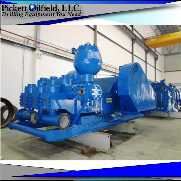
Mud Pump is one of the most critical equipment on the Rig; Powerful Mud Pumps pick up mud from the suction tank and circulate the mud down hole, out the bit and back to the surface.
In Rigs, two types of Mud Pumps are mostly used; namely, Triplex Pumps or Duplex Pumps, whereas Triplex Pumps have three pistons that move back-and-forth in liners. Duplex Pumps have two pistons move back and forth in liners.
Constant use of the Mud Pumps disturbs balancing of the Rotating components and the imbalance causes vibration, resulting in reduced Pump performance efficiency. To rectify such imbalanced Components and to retain the Pump performance efficiency, Dynamic Balancing is highly recommended.
Pump Group has taken receipt of the newest FLIR T420 Thermal Imaging Camera, to assist our engineers with various tasks – both on site and in our in-house Test Cell.
Thermal Camera use allows the operator to identify machine faults quickly and safely using non contact methods – meaning that plant & machinery doesn’t need to be shut down or isolated for the survey to be carried out.
Thermal imaging surveys can be carried out periodically without interfering with plant, and as temperatures of mechanical components increase as they wear, thermal imaging surveys allow our engineers to detect any change in the running temperatures and the high resolution screen pinpoints the source of the heat which indicates the source of the wear.
Thermal Imaging is now used in our In-House Performance Test Cell, where our engineers take thermographic images of the unit once the unit is up to temperature. This data is then saved with our Vibration Analysis data giving an overall base line for the condition of the unit post repair.
If you would like to discuss a potential thermographic survey, or wish to find out more about how Pump Group can utilise these modern techniques to reduce downtime and reduce maintenance costs, please contact a member of our team on +44 (0)161 864 4678 or by emailing sales@pumpgroup.co.uk

Thermal imaging can also be used to record mechanical temperature measurements (such as the temperature difference across a cooler) or to detect potential failures (such a rise in bearing temperatures)
Although standards do exist for Thermal imaging surveys, the results of a thermal scan are largely a matter of interpretation, knowledge of the equipment/process and an individuals experience.
Rigtech uses advanced solid state thermal imaging cameras combined with specialist software for the best results. The cameras are able to give ‘picture in picture’ results which help in the identification of the exact location of an anomaly.
The left hand cable is showing an elevated temperature, but the fault is actually in the right hand cable which was broken and not carrying current to a mud pump. All the current was passing through the other cable.


 8613371530291