
mud pump piston failure pricelist
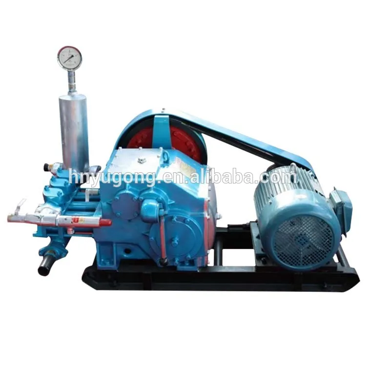
A mud pump is a reciprocating piston/plunger pump designed to circulate drilling fluid under high pressure (up to 7,500 psi (52,000 kPa)) down the drill string and back up the annulus. A duplex mud pump is an important part of the equipment used for oil well drilling.
Duplex mud pumps (two piston/plungers) have generally been replaced by the triplex pump, but are still common in developing countries. Two later developments are the hex pump with six vertical pistons/plungers, and various quintuplex’s with five horizontal piston/plungers. The advantages that Duplex mud pumps have over convention triplex pumps is a lower mud noise which assists with better Measurement while drilling and Logging while drilling decoding.
Use duplex mud pumps to make sure that the circulation of the mud being drilled or the supply of liquid reaches the bottom of the well from the mud cleaning system. Despite being older technology than the triplex mud pump, the duplex mud pumps can use either electricity or diesel, and maintenance is easy due to their binocular floating seals and safety valves.
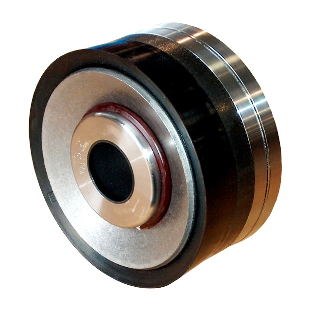
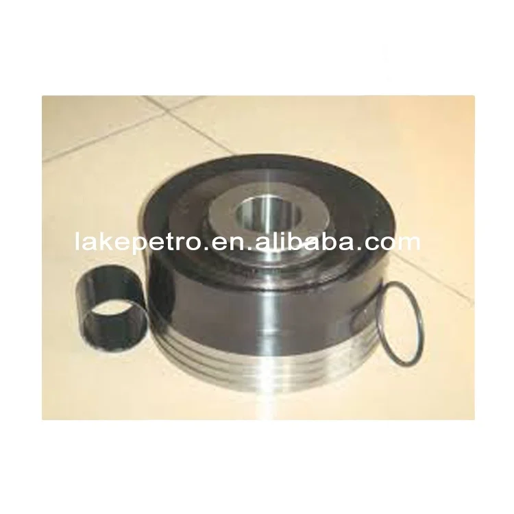
A mud pump is composed of many parts including mud pump liner, mud pump piston, modules, hydraulic seat pullers, and other parts. Parts of a mud pump:housing itself
Duplex pumps are used to provide a secondary means of fuel transfer in the event of a failure of the primary pump. Each pump in a duplex set is sized to meet the full flow requirements of the system. Pump controllers can be set for any of the following common operating modes:Lead / Lag (Primary / Secondary): The lead (primary) pump is selected by the user and the lag (secondary pump operates when a failure of the primary pump is detected.
Alternating: Operates per Lead / Lag (Primary / Secondary) except that the operating pump and lead / lag status alternate on consecutive starts. A variation is to alternate the pumps based on the operating time (hour meter) of the lead pump.

The mud pump piston is a key part for providing mud circulation, but its sealing performance often fails under complex working conditions, which shorten its service life. Inspired by the ring segment structure of earthworms, the bionic striped structure on surfaces of the mud pump piston (BW-160) was designed and machined, and the sealing performances of the bionic striped piston and the standard piston were tested on a sealing performance testing bench. It was found the bionic striped structure efficiently enhanced the sealing performance of the mud pump piston, while the stripe depth and the angle between the stripes and lateral of the piston both significantly affected the sealing performance. The structure with a stripe depth of 2 mm and angle of 90° showed the best sealing performance, which was 90.79% higher than the standard piston. The sealing mechanism showed the striped structure increased the breadth and area of contact sealing between the piston and the cylinder liner. Meanwhile, the striped structure significantly intercepted the early leaked liquid and led to the refluxing rotation of the leaked liquid at the striped structure, reducing the leakage rate.
Mud pumps are key facilities to compress low-pressure mud into high-pressure mud and are widely used in industrial manufacture, geological exploration, and energy power owing to their generality [1–4]. Mud pumps are the most important power machinery of the hydraulic pond-digging set during reclamation [5] and are major facilities to transport dense mud during river dredging [6]. During oil drilling, mud pumps are the core of the drilling liquid circulation system and the drilling facilities, as they transport the drilling wash fluids (e.g., mud and water) downhole to wash the drills and discharge the drilling liquids [7–9]. The key part of a mud pump that ensures mud circulation is the piston [10, 11]. However, the sealing of the piston will fail very easily under complex and harsh working conditions, and consequently, the abrasive mud easily enters the kinematic pair of the cylinder liner, abrading the piston surfaces and reducing its service life and drilling efficiency. Thus, it is necessary to improve the contact sealing performance of the mud pump piston.
As reported, nonsmooth surface structures can improve the mechanical sealing performance, while structures with radial labyrinth-like or honeycomb-like surfaces can effectively enhance the performance of gap sealing [12–14]. The use of nonsmooth structures into the cylinder liner friction pair of the engine piston can effectively prolong the service life and improve work efficiency of the cylinder liner [15–17]. The application of nonsmooth grooved structures into the plunger can improve the performance of the sealing parts [18, 19]. The nonsmooth structures and sizes considerably affect the sealing performance [20]. Machining a groove-shaped multilevel structure on the magnetic pole would intercept the magnetic fluid step-by-step and slow down the passing velocity, thus generating the sealing effect [21–23]. Sealed structures with two levels or above have also been confirmed to protect the sealing parts from hard damage [24]. The sealing performance of the high-pressure centrifugal pump can be improved by adding groove structures onto the joint mouth circumference [25]. The convex, pitted, and grooved structures of dung beetles, lizards, and shells are responsible for the high wear-resistance, resistance reduction, and sealing performance [26–28]. Earthworms are endowed by wavy nonsmooth surface structures with high resistance reduction and wear-resistance ability [29]. The movement of earthworms in the living environment is very similar to the working mode of the mud pump piston. The groove-shaped bionic piston was designed, and the effects of groove breadth and groove spacing on the endurance and wear-resistance of the piston were investigated [30]. Thus, in this study, based on the nonsmooth surface of earthworms, we designed and processed a nonsmooth striped structure on the surface of the mud pump piston and tested the sealing performance and mechanism. This study offers a novel method for prolonging the service life of the mud pump piston from the perspective of piston sealing performance.
The BW-160 mud pump with long-range flow and pressure, small volume, low weight, and long-service life was used here. The dimensions and parameters of its piston are shown in Figure 1.
A striped structure was designed and processed on the contact surface between the piston cup and the cylinder liner. The striped structure was 5 mm away from the outermost part of the lip, which ensured the lip could contact effectively with the cylinder liner. Based on the structural dimensions of the piston cup, we designed a 2-stripe structure, and the very little stripe space affected the service life of the piston [30]. Thus, the stripe space of our bionic piston was set at 5 mm. According to the machining technology, two parameters of stripe depth h and the angle between the stripes and lateral of the piston α were selected (Figure 2).
A mud pump piston sealing performance test bench was designed and built (Figure 3). This bench mainly consisted of a compaction part and a dynamic detection part. The compaction part was mainly functioned to exert pressure, which was recorded by a pressure gauge, to the piston sealed cavity. This part was designed based on a vertical compaction method: after the tested piston and the sealing liquid were installed, the compaction piston was pushed to the cavity by revolving the handle. Moreover, the dynamic detection part monitored the real-time sealing situation and was designed based on the pressure difference method for quantifying the sealing performance. This part was compacted in advance to the initial pressure P0 (0.1 MPa). After compaction, the driving motor was opened, and the tested piston was pushed to drive the testing mud to reciprocate slowly. After 1 hour of running, the pressure P on the gauge was read, and the pressure difference was calculated as , which was used to measure the sealing performance of the piston.
To more actually simulate the working conditions of the mud pump, we prepared a mud mixture of water, bentonite (in accordance with API Spec 13A: viscometer dial reading at 600 r/min ≥ 30, yield point/plastic viscosity radio ≤ 3, filtrate volume ≤ 15.0 ml, and residue of diameter greater than 75 μm (mass fraction) ≤ 4.0%), and quartz sand (diameter 0.3–0.5 mm) under complete stirring, and its density was 1.306 g/cm³ and contained 2.13% sand.
The test index was the percentage of sealing performance improvement β calculated aswhere and are the pressure differences after the runs with the standard and the bionic pistons, respectively ().
The sealing performance tests showed the striped structures all effectively enhanced the contact sealing between the piston and the cylinder liner. In particular, the increase of sealing performance relative to the standard piston minimized to 21.05% in the bionic striped piston with a stripe depth of 3 mm and angle of 45° and maximized to 90.79% in the bionic striped piston with the stripe depth of 2 mm and angle of 90°. Range analysis showed the sealing performance of pistons was affected by the stripe depth h and angle α, and these two parameters (h and α) have the same effect on the sealing performance.
Figure 4 shows the effects of stripe depth and angle on the sealing performance of mud pump pistons. Clearly, the stripe depth should be never too shallow or deep, while a larger angle would increase the sealing performance more (Figure 4).
Sealing validity tests were conducted to validate the sealing performance of the bionic striped pistons. It was observed whether the sealing liquid would leak at the tail of the cylinder liner, and the time of leakage was recorded. The standard piston and the most effective bionic piston were selected to compare their sealing performances.
Both the standard piston and the bionic striped piston leaked, which occurred after 84 and 249 minutes of operation, respectively (Figure 5). Figure 6 shows the pressures of the two pistons during testing. Clearly, the sealing pressure of the standard piston declined rapidly before the leakage, but that of the bionic piston decreased very slowly. After the leakage, the reading on the pressure gauge in the standard piston declined to 0 MPa within very short time, but that of the bionic piston decreased much more slowly.
The beginning time of leakage was inconsistent between the standard and bionic pistons (84 minutes vs. 249 minutes). In order to compare the leakage of these two pistons, the leaked liquid was collected when the piston started to leak. The volume of the leaked liquid was measured using a graduated cylinder every 5 minutes from the 84th minute and 249th minute, respectively (both considered as 0 minute), for 20 minutes. Figure 7 shows the leaked amounts of the standard piston and the bionic piston. Clearly, after the leakage and failure, the leaking speed and amount of the bionic piston were both smaller than those of the standard piston.
The piston lips and the cylinder liner were under interference contact, and their mutual extrusion was responsible for the lip sealing. Thus, a larger pressure between the piston lips and the cylinder liner reflects a higher lip sealing effect.
The bionic striped piston with the highest sealing performance (h = 2 mm, α = 90°) was selected for the sealing mechanism analysis and named as the bionic piston. The 3D point cloud data of standard piston were acquired by using a three-dimensional laser scanning system (UNIscan, Creaform Inc., Canada). Then, the standard piston model was established by the reverse engineering technique. The striped structure of the bionic piston was modeled on basis of the standard piston.4.1.1. Contact Pressure of Piston Surface
The standard piston and the bionic piston were numerically simulated using the academic version of ANSYS® Workbench V17.0. Hexahedral mesh generation method was used to divide the grid, and the size of grids was set as 2.5 mm. The piston grid division is shown in Figure 8, and the grid nodes and elements are shown in Table 3. The piston cup was made of rubber, which was a hyperelastic material. A two-parameter Mooney–Rivlin model was selected, with C10 = 2.5 MPa, C01 = 0.625 MPa, D1 = 0.3 MPa−1, and density = 1120 kg/m3 [32, 33]. The loads and contact conditions related to the piston of the mud pump were set. The surface pressure of the piston cup was set as 1.5 MPa, and the displacement of the piston along the axial direction was set as 30 mm. The two end faces of the cylinder liner were set as “fixed support,” and the piston and cylinder liner were under the frictional interfacial contact, with the friction coefficient of 0.2.
Figure 9 shows the pressure clouds of the standard piston and the bionic piston. Since the simulation model was completely symmetrical and the pressures at the same position of each piston were almost the same, three nodes were selected at the lip edge of each piston for pressure measurement, and the average of three measurements was used as the lip edge pressure of each piston. The mutual extrusion between piston and cylinder liner happened at the lip, and thereby the larger of the lip pressure was, the better the sealing performance was. The lip pressure of the standard piston was smaller than that of the bionic piston (2.7371 ± 0.016 MPa vs. 3.0846 ± 0.0382 MPa), indicating the striped structure enhanced the mutual extrusion between the bionic piston and the cylinder liner and thereby improved the sealing performance between the lips and the cylinder liner. As a result, sand could not easily enter the piston-cylinder liner frictional interface, which reduced the reciprocated movement of sand and thereby avoided damage to the piston and the cylinder liner.
Figure 10 shows the surface pressures from the lip mouth to the root in the standard piston and the bionic piston. The surface pressure of the bionic piston surpasses that of the standard piston, and the pressure at the edge of each striped structure changes suddenly: the pressures at the striped structure of the bionic piston are far larger than at other parts. These results suggest the contact pressure between the edges of the striped structures and the cylinder liner is larger, and the four edges of the two striped structures are equivalent to a four-grade sealed lip mouth formed between the piston and the cylinder liner, which generates a multilevel sealing effect and thereby largely enhances the sealing effect of the piston.
The piston surface flow field was numerically simulated using the CFX module of the software ANSYS® Workbench V17.0. The side of the lips was set as fluid inlet, and the other side as fluid outlet, as shown in Figure 11. The inlet and outlet were set as opening models, and the external pressure difference between them was 0 Pa. The moving direction of the piston was opposite to the fluid flow direction. The fluid region was divided into grids of 0.2 mm, while the striped structures were refined to grade 2.
Figures 12 and 13 show the surface streamline clouds and sectional streamline clouds of the two pistons at the early stage of leakage when the fluid entered the interface. Clearly, compared with the standard piston, when the surface-leaked liquid from the bionic piston passed the striped structure, the streamlines were sparse and significantly decreased in number, and the flow velocity declined more. The flow velocity decreased from 0.9348 m/s to 0.7555 m/s in the bionic piston and from 0.9346 m/s to 0.9262 m/s in the standard piston. It shows that, after the blockage by the striped structures, the striped structure more significantly intercepted the leaked liquid and could reduce the leakage rate of the piston, thereby enhancing the sealing effect.
Figure 13 shows the section leakage streamline of the standard piston and the bionic piston. Clearly, compared with the standard piston, when the leaked liquid of the bionic piston flowed through the striped structures, the streamlines would reflux and reverse inside the striped structures, indicating the striped structures can efficiently store the leaked liquid and slow down the leakage.
To better validate the sealing mechanism of the bionic striped pistons, a piston’s performance testing platform was independently built and the sealed contact of the pistons was observed. A transparent toughened glass cylinder liner was designed and machined. The inner diameter and the assembly dimensions of the cylinder liner were set according to the standard BW-160 mud pump cylinder liners. The sealing contact surfaces of the pistons were observed and recorded using a video recorder camera.
Figure 14 shows the surface contact of the standard piston and the bionic piston. Clearly, in the contact areas between the standard piston and the cylinder liner, only the narrow zone at the lip mouth contacted, as the contact width was only 4.06 mm. On the contrary, the contact areas between the bionic piston and the cylinder liner were all very wide, as the contact width was about 18.36 mm, and the sealed area was largely enlarged (892.8 mm2 vs. 4037.6 mm2) according to the contact areas calculated, which were favorable for improving the sealing performance.
Figure 15 shows the oil film left after the piston running. The oil film width of the bionic piston was far larger than that of the standard piston (20.48 mm vs. 2.28 mm). The striped structure of the bionic piston could store the lubricating oils, and uniform oil films were formed after its repeated movement, which reduced the friction between the piston and the cylinder liner, so that the seal failure of the piston would not happen due to excessive abrasion.
(1)The bionic striped structure significantly enhanced the sealing performance of the mud pump pistons. The stripe depth and the angle between the stripes and the piston were two important factors affecting the sealing performance of the BW-160 mud pump pistons. The sealing performance was enhanced the most when the stripe depth was 2 mm and the angle was 90°.(2)The bionic striped structure can effectively enhance the contact pressure at the piston lips, enlarge the mutual extrusion between the piston and the cylinder liner, reduce the damage to the piston and cylinder liner caused by the repeated movement of sands, and alleviate the abrasion of abrasive grains between the piston and the cylinder liner, thereby largely improving the sealing performance.(3)The bionic striped structure significantly intercepted the leaked liquid, reduced the leakage rate of pistons, and effectively stored the leaked liquid, thereby reducing leakage and improving the sealing performance.(4)The bionic striped structure led to deformation of the piston, enlarged the width and area of the sealed contact, the stored lubricating oils, and formed uniform oil films after repeated movement, which improved the lubrication conditions and the sealing performance.
The bionic striped structure can improve the sealing performance and prolong the service life of pistons. We would study the pump resistance in order to investigate whether the bionic striped structure could decrease the wear of the piston surface.

The piston is one of the parts that most easily become worn out and experience failure in mud pumps for well drilling. By imitating the body surface morphology of the dung beetle, this paper proposed a new type (BW-160) of mud pump piston that had a dimpled shape in the regular layout on the piston leather cup surface and carried out a performance test on the self-built test rig. Firstly, the influence of different dimple diameters on the service life of the piston was analyzed. Secondly, the analysis of the influence of the dimple central included angle on the service life of the piston under the same dimple area density was obtained. Thirdly, the wear of the new type of piston under the same wear time was analyzed. The experimental results indicated that the service life of the piston with dimples on the surface was longer than that of L-Standard pistons, and the maximum increase in the value of service life was 92.06%. Finally, the Workbench module of the software ANSYS was used to discuss the wear-resisting mechanism of the new type of piston.
The mud pump is the “heart” of the drilling system [1]. It has been found that about 80% of mud pump failures are caused by piston wear. Wear is the primary cause of mud pump piston failure, and improving the wear-resisting performance of the piston-cylinder friction pair has become the key factor to improve the service life of piston.
Most of the researchers mainly improve the service life of piston through structural design, shape selection, and material usage [1, 2]. However, the structure of mud pump piston has been essentially fixed. The service life of piston is improved by increasing piston parts and changing the structures of the pistons. However, the methods have many disadvantages, for example, complicating the entire structure, making piston installation and change difficult, increasing production and processing costs, and so on. All piston leather cup lips use rubber materials, and the material of the root part of the piston leather cup is nylon or fabric; many factors restrict piston service life by changing piston materials [3]. Improving the component wear resistance through surface texturing has been extensively applied in engineering. Under multiple lubricating conditions, Etsion has studied the wear performance of the laser surface texturing of end face seal and reciprocating automotive components [4–6]. Ren et al. have researched the surface functional structure from the biomimetic perspective for many years and pointed out that a nonsmooth surface structure could improve the wear resistance property of a friction pair [7, 8]. Our group has investigated the service life and wear resistance of the striped mud pump piston, and the optimal structure parameters of the bionic strip piston have improved piston service life by 81.5% [9]. Wu et al. have exploited an internal combustion engine piston skirt with a dimpled surface, and the bionic piston has showed a 90% decrease in the average wear mass loss in contrast with the standard piston [10]. Gao et al. have developed bionic drills using bionic nonsmooth theory. Compared with the ordinary drills, the bionic drills have showed a 44% increase in drilling rate and a 74% improvement in service life [11]. The present researches indicate that microstructures, like superficial dimples and stripes, contribute to constituting dynamic pressure to improve the surface load-carrying capacity and the wear resistance of the friction pair [12–21].
In nature, insects have developed the excellent wear-resistant property in the span of billions of years. For instance, the partial body surface of the dung beetle shows an irregularly dimpled textured surface with the excellent wear-resistant property that is conducive to its living environment [7, 8, 22]. The dung beetle, which is constantly active in the soil, shows a body surface dimple structure that offers superior drag reduction. These dimples effectively reduce the contact area between the body surface and the soil. Moreover, the friction force is reduced. Therefore, the dung beetle with the nonsmooth structure provides the inspiration to design the bionic mud pump piston. This paper proposed a new type of piston with dimpled morphology on its surface and conducted a comparative and experimental study of different surface dimpled shapes, thus opening up a new potential to improve the service life of the mud pump piston.
A closed-loop circulatory system was used in the test rig, which was built according to the national standard with specific test requirements. The test rig consisted of triplex single-acting mud pump, mud tank, in-and-out pipeline, reducer valve, flow meter, pressure gauge, and its principle, as shown in Figure 1. Both the pressure and working stroke of the BW-160 mud pump are smaller than those of the large-scale mud pump, but their operating principles, structures, and working processes are identical. Therefore, the test selected a relatively small BW-160 triplex single-acting mud pump piston as a research object, and the test results and conclusion were applicable to large-scale mud pump pistons. The cylinder diameter, working stroke, reciprocating motion velocity of piston, maximum flow quantity, and working pressure of the BW-160 triplex single-acting mud pump were 70 mm, 70 mm, 130 times/min, 160 L/min, and 0.8–1.2 MPa, respectively.
The mud pump used in the test consisted of water, bentonite (meeting the API standard), and quartz sand with a diameter of 0.3–0.5 mm according to actual working conditions. The specific gravity of the prepared mud was 1.306, and its sediment concentration was 2.13%. Whether mud leakage existed at the venthole in the tail of the cylinder liner of the mud pump was taken as the standard of piston failure. Observation was made every other half an hour during the test process. It was judged that the piston in the cylinder failed when mud leaked continuously; its service life was recorded, and then it was replaced with the new test piston and cylinder liner. The BW-160 mud pump is a triplex single-acting mud pump. The wear test of three pistons could be simultaneously conducted.
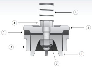
The mud pump piston used in the test consisted of a steel core, leather cup, pressing plate, and clamp spring. The leather cup consisted of the lip part of polyurethane rubber and the root part of nylon; the outer diameter on the front end of the piston was 73 mm, and the outer diameter of the piston tail was 70 mm, as shown in Figure 2. We proceeded in two parts during the design of the dimpled layout pattern because the piston leather cup consisted of two parts whose materials were different. The dimples at the lip part of the leather cup adopted an isosceles triangle layout pattern, and the dimples at the root part were arranged at the central part of its axial length, as shown in Figure 3(a). Dimple diameter (D, D′), distance (L), depth (h), and central included angle (α) are shown in Figure 3. The dimples on the piston surface were processed by the CNC machining center. Since then, the residual debris inside the dimples was cleaned.
Schematic of dimpled piston: (a) dimpled layout of piston, (b) dimpled array form diagram, (c) cross section view of the piston leather cup, and (d) original picture of dimpled piston.
The test program was divided into three contrast groups. The dimple depth in the test was 2.5 mm. Table 1 shows the comparison between the service life of dimpled piston with different diameters L-D1, L-D2, and L-D3 and that of the L-Standard piston. In Table 1, a comparison between the L-D4 piston with dimples at the leather cup root and the L-D2 piston is shown to study the influence of dimples at the leather cup root on the piston service life. Table 2 gives the influence of the dimple central included angle on piston service life when the dimple area density was the same by taking the L-D2 area density as a criterion. Table 3 displays a comparison of the wear patterns of pistons with different dimple diameters and L-Standard pistons under the same wear time. This object of the group test is to analyze the dimple wear pattern at the leather cup root under the existence of dimples at the roots of all leather cups.
Table 1 shows that average service lives of L-Standard, L-D1, L-D2, and L-D3 were 54.67 h, 57.17 h, 76.83 h, and 87.83 h, respectively. Therefore, the mud pump pistons with dimples provide longer service life than the L-Standard piston. As the dimple diameter increases, the piston service life was improved, and the largest percentage increase of the service life was 60.65%. The service life of the L-D4 piston was about 81.17 h, which increased by 7.94% compared with that of the L-D2 piston, indicating that the piston with dimples at the leather cup root could improve piston service life.
Figure 4 illustrates the surface wear patterns of pistons with different dimple diameters in the service life test. Figures 4(a) and 4(a′) show wear patterns on the surface of the L-Standard piston. This figure shows that intensive scratches existed in parallel arrangement on the piston leather cup surface, enabling high-pressure mud to move along the scratches from one end of the piston to the other easily, which accelerated the abrasive wear failure with the abrasive particles of the piston. Figures 4(b), 4(b′), 4(c), 4(c′), 4(d), and 4(d′) show the wear patterns of the leather cup surfaces of L-D1, L-D2, and L-D3 pistons, respectively. Figures 4(b), 4(b′), 4(c), 4(c′), 4(d), and 4(d′) show that the scratches on the leather cup surface became shallower and sparser and the surface wear patterns improved more obviously as the dimple diameter increased. If the piston leather cup surface strength was not affected to an extent as the dimple diameter increased, the reduced wear zone near the dimple would become greater and greater, indicating that the existence of dimples changed the lubricating status of the leather cup surface, their influence on nearby dimpled parts was more obvious, and they played active roles in improving the service life of the piston.
Surface wear patterns of pistons with different dimple diameters in the service life test: (a) L-Standard piston, (b) L-D1 piston, (c) L-D2 piston, and (d) L-D3 piston. (a′, b′, c′, d′) are partial enlarged pictures of (a, b, c, d).
Figure 5 displays the wear patterns of the leather cup root parts of the L-D4 and L-D2 test pistons. The wear patterns of the nylon root parts of the L-D4 pistons are fewer than those of the L-D2 pistons, as shown in Figure 5. When the leather cup squeezed out high-pressure mud as driven by the piston steel core, it experienced radial squeezing while experiencing axial wear. Therefore, the area with the most serious wear was the piston leather cup root part, and the friction force at the leather cup root was much greater than that at the other areas. The rapid wear at the root decreased the piston load-carrying capacity and then affected the service life of piston. The dimples at the piston leather cup root could reduce the wear of the piston leather cup root and improve the service life of piston.
Wear patterns of the piston leather cup root with and without dimples: (a) comparison chart of root wear of the L-D4 and L-D2 pistons, (b) partial enlarged diagram of root wear of the L-D4 piston, and (c) partial enlarged diagram of root wear of the L-D2 piston.
Table 2 indicates that the average service life of the L-S1 piston was 105.00 h, which is about twice that of the L-S2 piston (59.50 h) and was obviously improved in comparison with that of the L-D2 piston (76.83 h), indicating that, under the same dimple area density, the smaller the dimple central included angle was, that is, the closer the circumferential arrangement of dimples was, the longer the service life of the piston would be, and the increase of the maximum value of service life was 92.06%.
Figure 6 shows the surface wear patterns of the L-S1 and L-S2 test pistons. In Figures 6(a) and 6(a′), the scratches on the piston leather cup surface became sparse and shallow in the dimpled area. Figures 6(b) and 6(b′) show that the wear was slight in the area close to the dimples. The farther the scratches were from the dimpled area, the denser and deeper the scratches would be. The L-S1 piston had a small dimple central included angle, which was arranged more closely on the piston surface. The lubricating effects of oil storage in each row of dimples were overlaid very well, which was equivalent to amplifying the effect of each row of dimples in Figure 6(b), making the wear on the whole piston leather cup surface slight, preventing the entry of high-pressure mud into the frictional interface, and lengthening the service life of piston.
Wear patterns of pistons with different dimple central included angles under the same area density: (a) L-S1 piston and (b) L-S2 piston. (a′, b′) were partial enlarged pictures of (a, b).
Before all pistons have not failure, T1, T2, T3, and L-Standard experienced equal-time wear. This test set the wear time at 30 h. The piston leather cup mass was W0 before the test. After the test, the mass of the piston leather cup was W1. During the test, the wear loss of the piston leather cup was W = W0 − W1. The wear mass percentage of the test piston leather cup was calculated as φ = W/W0. The test results are shown in Table 3.
Table 3 shows that the average wear mass percentages of the L-Standard, T1, T2, and T3 pistons were 6.98%, 6.59%, 4.22%, and 3.83%, respectively. The wear mass percentages of the dimpled pistons were basically lower than those of the L-Standard piston and decreased as the dimple diameter increased. Figure 7 shows the wear patterns of the piston leather cup. The wear rules displayed in Figure 7 were similar to those displayed in Figure 4. The only difference was that the wear in Figure 7 was slighter than that in Figure 4. Based on the wear under the same time, the existence of dimples reduced the piston wear.
During the operation of the mud pump piston, the outside surface of the piston leather cup comes in contact with the inner wall of the cylinder liner and simultaneously moves to push the mud. The lip part of the piston leather cup mainly participated in the piston wear and exerted a sealing effect, while the piston root part mainly exerted centralizing and transitional effects. In the mud discharge stroke, the lip part of the piston experienced a “centripetal effect,” and a gap was generated between the lip part and the cylinder liner. The greater the contact pressure between the lip part and cylinder liner of the piston was, the smaller the gap was, and the entry of high-pressure mud into the contact surface between the piston and cylinder liner was more difficult. The piston root easily experienced squeezing under high pressure, and the smaller the equivalent stress caused by the piston root was, the more difficult the squeezing to occur. Hence, the contact pressure at the lip part of the piston and the equivalent stress at the root were analyzed, and they would provide a theoretical basis for the piston wear-resisting mechanism. The ANSYS Workbench module was used to perform a comparative analysis between the contact pressure at the lip part and the equivalent stress at the root of the three kinds of pistons (i.e., L-Standard piston, L-S1 piston, and L-D1 piston). The service life of the L-S1 piston exhibited the best improvement effect, whereas that of the L-D1 piston demonstrated the worst improvement effect. The piston adopted a 1 mm hexahedral grid, and the grid nodes and elements are as shown in Table 4.
We could obtain the contact pressure nephograms of the three pistons by analyzing the contact pressure of the lip parts of the L-Standard piston and two dimpled pistons, as shown in Figure 8.
The contact pressure nephograms of the three pistons indicate that the dimpled structure on the piston surface changed the distribution state of contact pressure. Three nodes were selected at the same position of each piston to obtain the contact pressure values. The node positions are shown in Figure 8(c), and the average pressure value of three nodes was the pressure value at the lip part of this piston. The contact pressure value of the L-Standard piston was 0.6027 MPa and that of the L-D1 and L-S1 pistons was 0.6840 MPa and 1.0994 MPa, respectively. Compared with the L-Standard piston, the contact pressure at the lip part of the L-S1 piston increased, the gap between the piston and cylinder liner became small, which could effectively prevent abrasive particles from participating in the wear and resulting in piston failure, and there was greater improvement in the service life of piston. The contact pressure of the L-D1 piston did not increase too much, and the degree of improvement of the piston service life was not obvious.
An equivalent stress analysis of the root parts of the L-Standard piston and two dimpled pistons was conducted to obtain the equivalent stress nephograms of the three pistons, as shown in Figure 9.
The equivalent stress nephograms of the three pistons show that the root of the L-Standard piston bore great stress and was easily squeezed, which accelerated piston wear and reduced piston service life. The dimpled structure could reduce the equivalent stress at the piston root and lengthen piston service life. Three nodes were selected in the same root positions of the three pistons. Their positions are as shown in Figure 9(c). The average value of the equivalent stresses of the three nodes was the equivalent stress value at the root of this piston. The equivalent stress value of the L-Standard piston was 0.1093 MPa, that of the L-D1 piston was 0.1066 MPa, and that of the L-S1 piston was 0.0922 MPa. The dimpled structure of the L-S1 piston could reduce the equivalent stress at the root and reduce the occurrence of root squeezing wear. The equivalent stress value of L-D1 did not decrease too much, and the degree of improvement of the piston service life was not obvious.
The lubricating oil on the mud pump piston surface could reduce the wear of piston and cylinder liner and improve the service life of pistons with the reciprocating movement. The lubricating oil would eventually run off and lose lubricating effect, which would result in piston wear. The finite element fluid dynamics software CFX was used to establish the fluid domain model of the dimpled and L-Standard pistons and analyze the lubricating state on the piston surface. The piston surface streamlines are shown in Figure 10. This figure shows that the lubricating fluid did not experience truncation or backflow phenomenon when passing the surface of the L-Standard piston. When the lubricating fluid flowed through the surface of the dimpled piston, it presented a noncontinuous process. Its flow velocity at the dimpled structure slowed down obviously because it was blocked by the dimpled structure.
Figure 11 shows the piston cross section streamline. This figure shows that the existence of dimples changed the distribution status of the lubricating flow fields on the contact surface between the piston and cylinder liner. The lubricating oil entered the dimpled structure in a large quantity, and the flow velocity slowed down. The dimpled structure on the piston surface enlarged the storage space of the lubricating oil and made it difficult for the lubricating oil inside the dimpled structure to be taken away by the cylinder liner to improve the lubricating conditions of the friction pair interface, reduce the frictional resistance between the piston and cylinder liner, reduce wear, and improve the piston service life.
When the piston moved in the cylinder liner, a small quantity of solid particles in mud entered gap of piston and cylinder liner and participated in abrasion. The dimpled structure on the piston surface could store some abrasive particles (as shown in Figure 6(a′)) during the piston wear process to prevent these particles from scratching the piston and cylinder liner and generating gullies, thus avoiding secondary damage to the piston and cylinder liner and improving the piston service life.
This paper presented a dimpled-shape mud pump piston; that is, the piston leather cup surface had a dimpled array morphology in regular arrangement. The experimental results can provide the basic data for design engineering of the mud pump piston with a long service life. The comparative analyses of service life and wear patterns for dimpled mud pump pistons and L-Standard pistons were conducted. The main results and conclusions were summarized as follows:(1)The service life of the mud pump piston with dimpled morphology on the surface improved in comparison with that of the L-Standard piston, and the service life increase percentages were from 4.57% to 92.06%.(2)The piston service life would increase with the dimple diameter under the same dimpled arrangement pattern, and the maximum increase in the value of service life was 60.65%.(3)The service life of the piston with dimples increased by 7.94% in comparison with that with none.(4)Under the same dimpled arrangement patterns and area densities, the tighter and closer the dimples were arranged on the piston surface, the longer the service life of piston was, and the maximum increase in the value of service life was 92.06%.(5)Under the same wear time, the wear of the dimpled piston slightly decreased in comparison with that of the L-Standard piston, and the minimum value of wear mass percentage was 3.83%.(6)The dimpled shape could not only change the stress state of the piston structure, improve piston wear resistance, and reduce root squeezing, but also increase oil storage space, improve lubricating conditions, and enable the accommodation of some abrasive particles. Furthermore, the dimpled shape was the key factor for the service life improvement of the mud pump piston.

Tired of changing mud pump pistons? We have your solution. The TD will work in all types of drilling mud including oil based, synthetic and water based. It was specifically designed to work in applications where water based mud is used or in situations where WBM is used on the top side & OBM is used on the bottom end. This eliminates the need for changing the piston midway through the drilling program. The “TD” or “Total Depth” name reflects our commitment to make a single piston that will last from “spud” to “TD”. This piston has been engineered with a unique friction reducing material bonded into the urethane of the sealing lip. Because the TD is built to withstand friction in the liner, wear on your parts is minimized and savings is maximized. The Patriot™ TD is also designed to meet pressures of 7500 psi as well as temperatures up to 220 degrees.

There are a lot of people who use the terms piston and plunger pump interchangeably. Granted, they are both positive displacement pumps and there are similarities, but their subtle differences are kind of a big deal when it comes to an operator’s desired performance, price, and pump longevity.
Plunger pumps have a reciprocating plunger (a type of rod). When it moves back and forth, it sucks liquid in through an inlet valve and forces it out the outlet valve. Plunger pumps have a stationary, high-pressure seal that is attached to the cylinder housing of the pump.
Piston pumps also have a reciprocating rod called a piston that moves back and forth to force liquid through a set of valves. Unlike a plunger pump, however, a piston pump’s seal is connected to the piston, meaning it moves in unison with the piston inside the cylinder housing.
From an engineering standpoint, it’s easy to understand that the main difference between piston and plunger pumps is the placement of the seals or O-rings. Again, the plunger pump’s seal is stationary while the piston pump’s seal moves with the piston.
When a reciprocating rod goes back and forth within either a piston or plunger pump, you have to seal it against the cavity wall so that it doesn’t lose compression. Because the seals of a plunger pump are not attached to a rod, it allows for less friction and higher pressure output. When the seal is connected to the moving part, as with a piston pump, the dynamic sliding action occurs along the walls of the housing, resulting in less pressure.
Here’s why. When a piston pump pushes a rod with an attached seal forward, you get friction that pushes back against the seal. Friction makes the seal want to react in the opposite direction of the motion, making the pump have to work harder to achieve more pressure.
A plunger pump has a smoother sliding action. Translation: less friction. In a plunger pump where the reciprocating rod doesn’t have an attached seal, the friction is in the same direction as the movement of the plunger. But the pressure is in the opposite direction, meaning they help to cancel each other out to some degree. Reduced friction means the motor doesn’t need to work as hard to achieve higher pressures.
Design for Manufacturability (DfM) comes into play when determining the durability of a pump’s design, especially in regards to which materials can be used where.
The material makeup of a pump’s housing and the reciprocating plunger or piston will have the greatest impact. In general, you want the component that has the greatest potential for wear to be as hard as possible to avoid scratches and a broken seal.
Common materials used in the pump industry include anodized aluminum, stainless steel, and brass. But the hardest available material used in some pump designs is ceramic. It doesn’t wear out over time like most metals, plus it has great chemical compatibility. It can be polished to a very consistent and smooth surface finish which is perfect for creating a tight seal.
Why does this matter? In a plunger pump, it’s the plunger that needs to seal against the cavity wall, meaning it should be the hardest material possible. In a piston pump, it’s the cavity walls that need to seal against the rod with the O-ring, meaning the cavity wall needs to be as strong as possible.
However, engineering and fabricating a thin, tube-like cavity wall out of ceramic or other material and making the inside of it perfectly smooth and consistent is a much greater challenge than fabricating the exterior of a perfectly smooth plunger out of those same materials. Even if it were possible to make the internal housing walls out of ceramic, its poor tensile strength would quickly lead to cracking and pump failure.
In other words, it’s much easier to make the plunger out of hard materials than it is to make the housing out of those same materials. As a result, plunger pumps can be engineered to be much more durable than piston pumps.
Many piston pumps require an oil bath. Some versions also have a second oil reservoir or oil pan with a wick to lubricate the backside of the piston seal. These reservoirs need to be refilled and maintained if you want to keep the pump operating as it should.
Many plunger pumps, like those manufactured by Pumptec, have oil that is contained in a sealed chamber and do not require draining or refilling of any oil reservoirs.
The more parts you have, the more maintenance is required. Plunger pumps have a relatively simple design, fewer parts, and require much less maintenance than piston pumps. Simply put, there’s less that can go wrong with a plunger pump.
What else results from fewer parts and a simpler design? Lower cost. Plunger pumps, in general, can have considerably lower up-front costs than piston pumps when comparing similar performance. Their total cost of ownership is typically less, too, especially when you factor in maintenance, repairs, or replacement over time.
If you haven’t guessed by now, we’re a bit biased toward plunger pumps. Many of the reasons stated here are why our company ventured into the industry in the first place: we saw the need for better durability and performance at a fair price point.
If you’re in the market for high-performance, high-pressure electric commercial pumps for your industry application, get in touch with our team of pump experts. We’re happy to talk through your needs and challenges to determine a solution.
Curious about some of the terms used in this article? We developed a helpful Pump Terms Glossary with common terms and relevant information. Click below to download your copy today.

The fluid end of a duplex or triplex pump offers hundreds of opportunities for error. The results of an error in such a high-pressure system can mean (1) expensive downtime on the pump and maybe the entire rig, (2) expensive repair-replacement, and (3) possible injury or death of a crewman or a company man. Under the laws of nature, pump pistons and liners will wear, and there will be some corrosion and metallurgical imperfections, but the majority of pump failures are manmade. Theoretically, thorough training and retraining should avoid most mud pump problems. Realistically, a critical failure analysis during repair will be necessary to determine how to correct the failure. Telltale signs of trouble are distortion of piston rods, frayed piston polymer, discoloration, odor, hard-to-remove piston, rod cracks, pitting, total fracture, valve seat wear, and unsuitable external appearance.

A Mud pump features robust reciprocating pumping technology for mud circulation on the drilling array. Reciprocating pumps follow the conventional mechanism of the auto engine.
Having a crosshead crankshaft gear makes the mud pump mechanism more effective. And the specific placement of the connecting rod helps the piston to play its role.
The fixed part of the piston rod, along with a sleeve, ensures compelling performances. In this position, it can work without any force on pistons from sideways.
And in this position, a cooling spray of water on the pump’s pistons helps it work better. As well as other moving portions like liners also work better with cooling water spray.
The mud pump works as a virtual device featured in the well drilling kit. Unlike a stand-alone device, this kind of pump works as major equipment of robust drilling equipment.
Both output and input fluid flows through the direct pipeline towards the drilling string. The advanced connectivity with structured fixtures of the borehole helps a mud pump to perform the best.
In the case of remote locations, the mechanism of diesel motors suits this kind of pumping unit. On the availability of DC motor kits, a mud pump features electric energy driven AC motors.
The surface of this kind of deep well can be spacious up to 10 miles. So, in these cases, a mud pump must work on the 10 miles below the water surface.
The types of a mud pump depend on its specific combo of components. According to the requirements of the clients, this pump features the best equipment.
The number of working ends of a pump’s piston defines the pattern of action. Having a single working end of the piston, a Single-acting mud pump can use only one direction.
For a wide range of drilling applications, this kind of pumping unit works the best. In these applications, a pump needs to generate a high amount of pressure.
The Duplex mud pump’s competent mechanism helps to ensure the standard mud circulation as it can reach from the mud picking system to the bottom point of the well.
All these components provide the best performance executing the top-tier mechanism. In case of severe vibration, this pumping unit requires a suction unit.
Maintenance is a vital thing to boost the lifespan of a pump. If you go through the following essential key points, you will learn how to enhance a mud pump’s performance.
Regular servicing is a standard part of maintenance for any mechanical unit. But, most of the maintenance shop complains about the abuse of pumping components without any oil treatment.
Checking and changing the oil daily makes your mud pump more efficient. If you detect any mud or water contamination in existing oil, don’t hesitate to change it.
So, users should take care of the gear end from mud deposits. Otherwise, it will ruin pony rod packing. It’s one kind of mechanical failure, which can shred pistons and liners.
This kind of potent system contains a tank along with a spray bar and a small pumping unit. Using the spray bar, the tank moves out the fluid from the tank.
Always remember where a mud pump deals with drilling fluid, it should be free of solids. The drilling fluid can be raw water or other combination of liquid. But it needs to be solids-free.
For the recycling process of your fluid, always prefer a standard mud recycling system. As well as checking the reliable content throughout the day enhance the performance of your system.
A triplex mud pump works with minimal suction pressure. One thing you need to remember is the maintenance of this suction pressure with consistency during application.
All pulsation dampeners utilize one of two methods for mitigating energy produced by reciprocating pumps; compression or exchange. The traditional gas-charged dampeners use a compressible gas cushion, either by a gas over liquid or gas-filled diaphragms, bladders, or cartridge. As the reciprocating pump produces pressure spikes, the gas compresses, thus absorbing the pressure difference and smoothing the pumped media flow. For maintenance free pulsation dampeners, rely on energy exchange. There is a common misconception regarding maintenance free pulsation control devices that the pumped media is compressible enough to absorb the reciprocating pumps’ pressure spikes. This is not true. However, the maintenance free pulsation dampeners work by utilizing the kinetic energy exchange. This kinetic energy exchange can only happen if the pulsation dampener’s volume is large enough to dissipate enough energy to reduce the adverse effects caused by the reciprocating pump. This is why maintenance free pulsation devices require massive volumes to be effective. Sigma Drilling Technologies has developed a pulsation dampening system that utilizes both methods for reducing the harmful effects of positive displacement pumps, both compression and exchange.
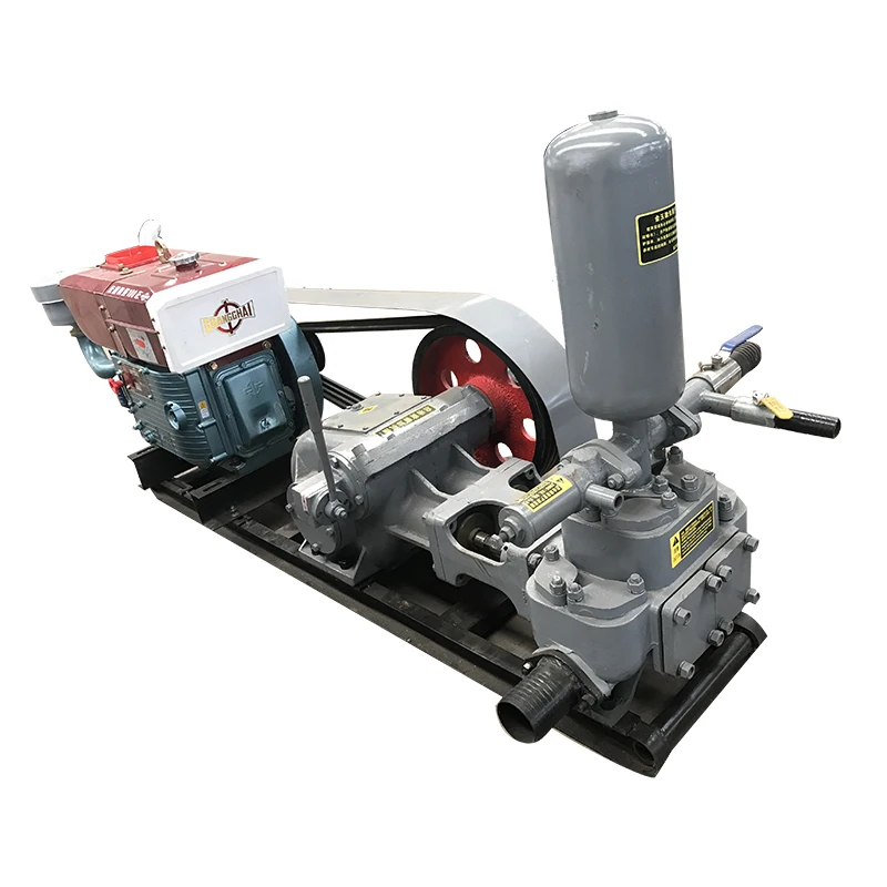
2.BW mud pump have four gear shifts.Output and drilling depth are adjustablr,so it can be used to grout cement slurry or equuipped with drilling machine.
3.BW grouting pump is widely used in railway,hydraulic engineering,matallurgical engineering,building construction,geological exploration,engineering exploration.
It is mainly used for core drilling rig supporting transportation slurry,also can be used for other aspects of grouting,mine drainage and long-distance water supply and other uses.The pump has low energy consumption,flexible operation,high quality and durability,good decomposability ad easy relocation.Drilling cycle water power source.
GEHO slurry pumps from Weir Minerals Netherlands are put to the test in some of the most extreme environments the world has to offer. And they are expected to work without fail.
Blue and shiny, the piston diaphragm pump stands in the factory hall, ready to be shipped to China for use in an aluminum factory. “The pump, a digester feed pump, was built and tested here,” explains Marjo Cox, public relations manager at Weir Minerals Netherlands, situated in Venlo. “The design was tailored to provide optimum performance in its specific application. The pumps are installed by one of our own commissioning engineers in China. He then instructs the local people on maintenance and operation.”
“Broadly speaking our pumps are used for three applications in mining,” he continues. “Firstly, they are used for pumping slurry over long distances, from the mine or extraction area to a port or processing plant. Secondly, the pumps deliver slurry directly to the system for removing the mineral or ore from the rock. Finally, they are used for pumping residual products such as red mud [a waste product in bauxite processing] or fly ash to a dump or back into an unused mine shaft. On a global scale, we are the leading player in all three applications, in particular in pipeline transport, with a market share of more than 90 percent.”
The company has a long history in pumping liquids and slurries. Even before World War II, Weir Minerals Netherlands (then GEHO Pompen) was involved in the manufacture of pumps for discharging ground-water. The products developed by pumping ever- thicker liquids such as sewage sludge and industrial sludge, until by the 1960s the pumps were capable of pumping ore slurry.
Slurry is crushed raw materialmixed with water. The problem is that direct contact between abrasive slurry and moving parts in a pump quickly leads to wear. The development of the piston diaphragm pump by GEHO in the 1970s offered a solution. With this system, the slurry is separated from the vulnerable moving parts of the pump by a membrane. At the time, an entire test installation was built at the GEHO factory to study the behavior of bauxite and other mineral slurries.
The first customer for a GEHO piston diaphragm pump was the German aluminum manufacturer VAW, which in 1974 needed a system for use in the German Ruhr area. Customers such as Hoechst and Thyssen Stahl soon followed. Initial contacts were then established with North America, and a small network of international agents was formed.
“The world of mining is relatively close-knit,” says Cox. “Your reputation is your most valuable possession. It is essential that you deliver a top-line product in terms of quality, service life, operation, availability and of course reliability. If a pump shuts down, the whole system grinds to a halt.”
The international expansionof GEHO took on a new dimension in 1990 following its takeover by U.S. company Baker Hughes. In 1994, Baker Hughes transferred all pump production activities to the Scottish Weir Minerals (see sidebar). “Becoming part of an international organization was a logical step for GEHO,” Joosten says. “We were able to retain our identity, and we remained responsible for sales, production and development. But we also gained access to an inter-national infrastructure of Weir sister companies. We could profit from a wealth of knowledge and experience and from a financially powerful parent company that enabled us to participate in larger projects.”
One mega project in Brazil recently involved the delivery of 18 pumps, to be installed in two pump stations, for a 340-mile-long pipeline. Each pump weighs 80 tons and 125 semi-trailers will be needed to transport the pumps to the port.
“A pump is not a standard product,” Joosten emphasizes. “We make our designs taking into account the application, ambient factors and the type of slurry. Each slurry has its own characteristics. First a sample of the slurry is examined in our laboratory for rheological characteristics. Depending on the outcome, we advise on or select the relevant materials, ranging from standard steel through to solid titanium.”
“The circumstances are different wherever we operate,” he continues. “They range from –40°F in Alaska and Siberia to more than 100°F in New Guinea, 10,000 feet under the ground in South Africa up to 13,000 feet in the Andes. Such extreme conditions can influence, for example, the operation of the electronic control equipment. Via the lubricating oil that flows right around the pump, we can cool or heat the system.”
Given the highraw-material prices and the tremendous demand from emerging markets over the past decade, business has boomed at Weir. “Our strength has always been our ability to supply products quickly,” Joosten says. “But at one point it became difficult for us to obtain our materials from our suppliers of wrought and cast work and moving parts. We faced the bizarre situation that there was simply not enough steel available to make the pumps that had been ordered for iron ore mines. Because every pump is tailor-made, it is almost impossible to complete work in advance, and that leaves little time for our suppliers. We eventually solved the problem by buying capacity, enabling us to get the products in time.”
Joosten adds, “Pumps are constantly developing. I predict trends involving more energy-efficient and more process-specific pumps with tailor-made work, in particular for high-temperature pumping. And as it happens, we are specialists in tailor-made products. And of course, pumps must never fail.”
A mud pump is a reciprocating piston or plunger device designed to pump drilling fluid under high pressures and volumes down the drill string of a drilling rig. The main functions of drilling fluid are to provide hydrostatic pressure to prevent formation fluids from entering and to stabilize the bore, to keep the drill bit cool and clean, to carry drill cuttings back out to the surface, and to suspend the drill cuttings while drilling is paused or during the pullback process.
Mud pumps consist of two main sub-assemblies- the fluid end and the power end. The fluid end performs the pumping process with valves, pistons, and liners, or plungers and stuffing boxes- depending upon the type used. These components are considered expendables, and are designed to be easily replaced in the field. The power end contains the eccentric or crankshaft, along with the connecting rods, and cross heads/slides.
Tulsa Triplex is a Tulsa Rig Iron company. We manufacture pumps from 100 to 600 horsepower that are designed to be easily maintained and are capable of being completely rebuilt. Our pumps feature a smaller footprint and lighter weight than competing models, making them completely legal load size and weight in most instances. They are available as a bare pump, with chainbox, or a complete skidded package.


 8613371530291