
mud pump piston liner free sample

Alibaba.com offers 1113 mud pump liner products. About 56% % of these are mud pump, 7%% are mining machine parts, and 3%% are other oil field equipments.
A wide variety of mud pump liner options are available to you, You can also choose from oil well, mud pump liner,As well as from chromium, carbon steel, and iron. and whether mud pump liner is moulding, cutting, or bending.

The 2,200-hp mud pump for offshore applications is a single-acting reciprocating triplex mud pump designed for high fluid flow rates, even at low operating speeds, and with a long stroke design. These features reduce the number of load reversals in critical components and increase the life of fluid end parts.
The pump’s critical components are strategically placed to make maintenance and inspection far easier and safer. The two-piece, quick-release piston rod lets you remove the piston without disturbing the liner, minimizing downtime when you’re replacing fluid parts.

The invention relates to an assembly for quickly securing and releasing a component to a pump housing and more particularly to a retainer assembly for releasably mounting a piston liner within a hydraulic cylinder on the module of a pump.
Heavy duty large horsepower pumps are used to pump fluids or slurries with entrained solids. In the oil industry, for example, slush or mud pumps are used to pump viscous fluids, such as drilling muds, cement, or other well fluids. Although mud pumps may be either centrifugal or reciprocating type pumps, typically mud pumps are reciprocating pumps using one or more pistons and hydraulic cylinders with liners to generate the high pressures required to pump these viscous fluids in and out of the well.
Mud pumps include a fluid end and a power end. In the fluid end of one type of a triplex mud pump, for example, there are three sets of suction modules and discharge modules in fluid communication. A suction manifold is connected to the fluid inlets of the suction modules for receiving fluids and passing those fluids to each of the suction modules. A discharge manifold is connected to the fluid outlets of the discharge modules for discharging the pumped fluids. Each module encloses a set of flow passages with check valves for controlling the direction of flow of the fluids. A check valve is disposed at the suction module fluid inlet to only allow fluids to enter the suction module inlet end of the module and another check valve is disposed at the discharge module fluid outlet to only allow fluids to exit the the discharge module for flow into the discharge manifold.
Each discharge module includes a liner retainer flange attached to the discharge module. The liner retainer flange attaches to a replaceable liner within which a pump piston reciprocates. The piston is a generally cylindrical steel member having a polymer, such as polyurethane, bonded to its outer diameter for sealingly engaging the inner cylindrical wall of the liner to ensure a fluid tight seal required for drawing the low pressure fluids through the suction manifold and module flow passages. The seal integrity must be maintained to withstand the high discharge pressure on the discharge stroke. The power end contains the gears that reciprocate the pump piston within the liner for pumping the fluid through the module passages in the fluid end and thence out the discharge valve.
In operation, on the suction stroke, the pump piston draws fluids through the suction manifold and suction valve as the piston strokes within the liner. On the discharge stroke, the check valve in the discharge module opens simultaneously as the suction valve closes preventing suction back flow into the suction module. Fluid in the liner is compressed and pressure is built up until the pressure overcomes well bore pressure so as to pump the mud into the well. The piston then reverses for another suction stroke whereby the check valve in the suction module opens and the discharge valve closes simultaneously, the piston now making a suction stroke.
As the piston reciprocates within the liner, friction wears the liner. Further, the fluid passing through the fluid end includes particulates and other solids which wear away and destroy the liner and piston. When the liner and piston degrade, the fluid seal is lost and the pump becomes much less efficient. Also, the reciprocation of the piston in the liner causes pulsations that over time cause the liner to become loose within the containment of the liner retainer flange thus resulting in a degradation of the seal at the face of the liner and the seal at the face of the liner wear plate. Therefore, it is important to be able to replace the liner as a part of routine maintenance (or when emergencies occur from seal failure while drilling) to ensure that the pump operates efficiently and can control well pressure. It is also important to have a means for fastening the liner to the liner retainer flange so as to ensure that the liner remains firmly secured despite extended reciprocation of the piston assembly within the liner.
Typically each liner retainer flange, and the cradle of the pump power end are all secured to the fluid end module by studs and threaded connections. Because of the environment in which the mud pump operates and the corrosive nature of the fluids being pumped, the studs and threaded connections, such as nuts, become corroded and are difficult to unthread for the replacement of the liner. Often, the threaded connections have been over tightened, making it even more difficult to unthread. Where the liner is retained by an end cap, a steel bar is inserted into a guide hole in the side of the end cap and then the cap is unscrewed using a significant amount of torque. This end cap is very heavy as it must have sufficient strength to keep the liner from moving, even with pressures up to 7500 psi. Where a nut or end cap resists unscrewing, a sledge hammer is used to hammer on a socket wrench or a special hammer wrench is used to loosen the nut or cap. Such activity is obviously dangerous. In some regions of the world local laws prohibit the use of sledge hammers for personnel safety reasons or to avoid the risk of an explosion due to sparks.
Prior art liner retention systems include spring mechanisms around each stud with an end flange for securing the liner against a fluid end module. Hydraulic pressure is applied to the spring mechanism of each stud by a small hydraulic pump to remove the clamping force of the spring mechanism. The release of the clamping force allows the removal of the clamping flange of the liner retention system. Individually actuated spring loaded studs cause an uneven pressure to be applied to the clamping flange. Further, the clamping force is limited because of the limited space available to hold numerous springs.
The liner retainer assembly of the present invention includes a liner retainer flange that is mounted on the discharge module of the fluid end of a pump. A pressure actuated hydraulic clamping piston with related actuated, conical dished washers and necessary static and sliding seals is disposed within the retainer flange . The hydraulic pressure actuated clamping piston is configured to receive and hold the liner. The hydraulic clamping piston and an end cap maintain the liner in contact with the module during actuation. The hydraulic clamping cylinder includes a counterbore which is divided by the hydraulic piston into a fluid cavity and a spring cavity. The spring cavity houses a plurality of springs which bias the hydraulic piston, end cap, and liner towards the module, thus providing a strong clamping securing force when the hydraulic pressure is released. The fluid cavity communicates with a supply of hydraulic fluid for biasing the hydraulic piston away from the module to activate the springs. By pressurizing the fluid cavity, the springs are compressed so as to disengage the liner retaining end cap from the liner and allow the unthreading of the liner end cap to then remove the liner.
The liner retainer assembly permits preloading or prestressing of the liner against the module of the fluid end of the pump so that the liner will not loosen upon the reciprocation of the pump piston within the liner. Further, the liner may be easily secured and unsecured from the module without the necessity of a sledge hammer or other methods for applying excessive amounts of torque to a securing fitting. The assembly of the present invention permits the easy and quick replacement of the liner as necessary.
FIG. 1 is a cross-sectional view of a typical liner inserted into a liner retaining flange housing assembly constructed in accordance with the present invention.
FIG. 2 is a cross-sectional view and partial exploded view of the liner retaining flange assembly of FIG. 1 illustrating the application of hydraulic pressure for the attachment of a retaining cap.
FIG. 3 is a cross-sectional view of the liner retaining flange assembly of FIGS. 1 and 2 following the attachment of the retaining cap prior to energizing the Belleville washers.
Referring first to FIGS. 1 and 2, there is shown a fluid end module 10 and a cradle 28 of the pump power end. The pump is of the type used to pump fluids, such as drilling muds, cement or the like. Pumps of this type are well known. A wear plate 14 defines a bore 16 which leads into liner 20. The module 10 is used for the transfer of fluid from the suction manifold and suction module (not shown) to the discharge manifold (not shown) and discharge module.
An exemplary liner retaining flange assembly 18 of the present invention is used to secure liner 20 within a hydraulic cylinder 30 mounted on module 10 and liner retainer flange 22. Those of skill in the art will understand that a pump piston (not shown) attached to the power end of the pump is reciprocated within the liner 20 to effect the desired pumping action to flow fluid through the fluid end module 10 of the pump. Hydraulic cylinder 30 provides an open end into which the liner 20 is inserted. Module 10 also provides a counterbore 12 for the adjacent wear plate 14 against which it is desired to retain the liner 20 during operation of the pump piston. It can be appreciated that the purpose of wear plate 14 is to avoid the end of liner 20 wearing module 10 due to the reciprocation of the piston within liner 20. However, wear plate 14 may cause wear to the module 10 if the liner 20 is not securely affixed. Wear plate 14 may be replaced should that wear become excessive. It is noted that the end of the liner 20 adjacent the wear plate 14 includes an internal annular groove 59 with seal member 61 for sealingly engaging the wear plate 14 and the other open end 15 of liner 20 includes an external annular load-bearing shoulder 60 which retains end cap 64 (FIG. 2).
The hydraulic cylinder 30 includes a threaded, reduced diameter portion 24 and an enlarged diameter portion 32. Reduced diameter portion 24 is secured in a threaded or splined relation at 23 to liner retainer flange 22 that is located in an abutting relation to the module 10. Bolted studs 26 secure the cradle 28 of the pump power end, the liner retaining flange 22 and hydraulic cylinder 30 to module 10.
The enlarged portion 32 of hydraulic cylinder 30 includes an inner clearance cavity 33 which has a reduced diameter neck, forming a hydraulic cavity 58 to activate hydraulic piston 42 which in turn compresses springs 56 which are restrained from escaping from the spring cavity 35 by retainer ring 48. Hydraulic sealing is accomplished by sealing rings 39 and 49. End cap 64 is held in place with external threads 46. A hydraulic fluid port and fitting 38 is disposed through the wall of enlarged diameter portion 32.
When these components are assembled, the annular flange 44 of piston 42 forms hydraulic cavity 58 and outer spring cavity 35. The hydraulic fluid port and fitting 38 communicates with hydraulic cavity 58 for applying hydraulic pressure to flange 44. The spring cavity 35 houses a plurality of axially compressible Belleville springs or washers 56. Retainer ring 48 has external threads 50 which threadingly mate in a complimentary fashion with the internal threads 34 of enlarged diameter portion 32. The washers 56 bear against the retainer ring 48 and annular flange 44. Enough springs are used so as to insure sufficient force is generated to prevent movement of liner 20 when pump pressure is at maximum. The retainer ring 48 secures the washers 56 and hydraulic piston 42 within the enlarged diameter portion 32 of hydraulic cylinder 30. O-ring 49 provides a fluid-tight seal between the piston 42 and enlarged diameter portion 32.
Upon assembly as shown in FIG. 1, hydraulic piston 42 has previously been inserted into enlarged diameter portion 32 of cylinder 30 to form cavities 58 and 35. Belleville washers 56 are inserted into outer spring cavity 35 and retainer ring 48 is threaded into place. The liner 20 is inserted into the outer hydraulic cylinder 30 of liner retaining assembly 18 so that the end of the liner 20 with seal 61 abuts wear plate 14.
Referring particularly to FIG. 2, the retaining assembly 18 is shown ready to secure the liner 20 in place. A hydraulic hose 62 is secured to the external port and fitting 38 for supplying hydraulic fluid to inner hydraulic cavity 58. As fluid pressure is supplied to cavity 58, fluid pressure is exerted against flange 44 urging piston 42 outward toward retainer ring 48. As annular flange 44 of piston 42 is so moved, springs 56 are axially compressed. As springs 56 are compressed, the threaded end 46 of piston 42 extends further away from wear plate 14 and module 10.
In the outward and extended position of piston 42, end cap 64 is threaded onto the threaded end 46 of the piston 42 so the threads 46 mate with the threads 66 of end cap 64. End cap 64 need only be hand tightened. It is noted that liner load bearing shoulder 60 mates with the shoulder 68 on end cap 64.
Referring now to FIG. 3, the retaining assembly 18 is shown completely assembled with the liner 20 securely affixed within the hydraulic cylinder 30. Once end cap 64 has been affixed, the fluid within the hydraulic cavity 58 is evacuated through port and fitting 38 permitting the springs 56 to bias flange 44 toward wear plate 14 and module 10 and bias end cap 64 against the other end 15 of liner 20. As the hydraulic pressure in the hydraulic cavity 58 is released, stored energy from the compression of springs 56 is released to load the liner 20 longitudinally. As a result, the energy stored by compressing springs 56 is transmitted to the liner 20 in order to load it longitudinally against wear plate 14 and module 10.
In order to remove the liner 20, the procedure is substantially reversed. Fluid is introduced into the hydraulic cavity 58 through port and fitting 38 in the same manner as previously described to compress springs 56 and external piston 42. Once spring forces are removed, end cap 64 may then be unthreaded. Fluid is bled off, springs 56 are decompressed and the unit is stabilized.
It is noted that the arrangement of the present invention permits a liner to be replaced rapidly and easily and without the use of extra tools or having to apply excessive torque. Further, a prestress force is applied to the liner 20 so that it is longitudinally compressed against wear plate 14 and module 10. This load or prestress securely holds the liner 20 against the wear plate 14 despite repeated reciprocation of the pump piston within liner 20.
Referring now to FIGS. 4 and 5, an alternative embodiment for an exemplary retaining assembly 70 is illustrated with the liner 20 inserted and securely affixed therewithin. For simplicity, like reference numerals are used for like or similar components. FIG. 5 is a cross-sectional view of the hydraulic cylinder 36 taken along plane V--V in FIG. 4.
In this embodiment, hydraulic cylinder 36 defines a plurality of individual piston chambers 72. There are 4, 6, or 8 chambers 72 (depending on the holding force required) which are azimuthally spaced around hydraulic cylinder 36. Each piston chamber 72 contains a wear cylinder sleeve 101 with an individual piston 74 that is reciprocably disposed therein. Wear sleeve 101 includes threaded bores 103 for receiving bolts to assist in the replacement of sleeves 101 when excessive wear has occurred. Each piston 74 provides an elongated shaft 76 and a radially extending flange 78 so that when disposed within the chamber 72, the chamber 72 is divided into a spring retaining chamber 80 and fluid chamber 82. The shaft 76 of the piston 74 is threaded at 84 for threadingly receiving a nut 86. Fluid may be introduced into the fluid chamber 82 through an associated hydraulic fluid port and external fitting 38.
A cover 88 is placed over the open end 15 of liner 20, the cover 88 having a central opening 90 through which liner 20 is disposed. The cover 88 also includes apertures 92 for the disposal of each piston shaft 76. The cover 88 serves to provide a solid surface against which Belleville springs 94 may be compressed. O-ring seals 96 surround the flange 78 of each piston 74 to ensure fluid sealing.
An end cap 98 is shown disposed over the cover 88. The end cap 98, like the cover 88, provides apertures 100 for receiving piston shafts 76. However, the central aperture 102 is only large enough to permit a portion of the liner 20 to be disposed therethrough, creating a shoulder 104 which mates with the shoulder 60 of liner 20.
Referring particularly to FIG. 5, a plurality of fluid passages 106 are provided in hydraulic cylinder 36 which interconnect and communicate with each piston chamber 72 and each of the ports and fittings 38 on the hydraulic cylinder 36. The fluid interconnection permits all of the fluid chambers 82 (FIG. 4) to be filled with fluid by using only one or a few of the hydraulic fluid ports and fittings 38 for injecting fluid. The common communication with all fluid chambers 82 also allows the common hydraulic actuation of all the pistons 74 (FIG. 4).
In operation as shown in FIG. 4, the liner 20 is installed and removed in a manner similar to that described with respect to liner retaining assembly 18. Fluid is introduced into each individual fluid chamber 82 urging the associated piston 74 to move toward the open end 15 of liner 20. Energy is stored through axial compression of the Belleville springs 94. The end cap 98 is placed onto the liner open end 15 so that the shoulder 104 engages shoulder 60 of liner 20. Nuts 86 are then tightened onto each piston 74. Again, the nuts need only be hand tightened. Fluid is then evacuated from the fluid chambers 82 and the Belleville springs 94 bias pistons 74 toward the wear plate 14 and the module 10, thus loading liner 20 longitudinally against wear plate 14 and module 10.
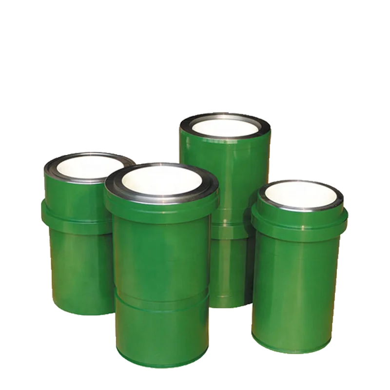
Function: Mud Pump Liner also called the cylinder liner. The cylinder liner is the core accessory of the mud pump, which has the functions of storing mud, bearing pressure and completing the suction and discharge of mud. Because the cylinder liner is in direct contact with the mud, it is easy to be worn and corroded by the tiny sand particles, acid and alkali liquid in the mud during work. As a result, the inner diameter of the cylinder liner becomes larger, leakage occurs in the seal between the cylinder liner and the piston, and the pressure is reduced. The cylinder liner is scrapped eventually. Cylinder liner is a one-time wearable part that cannot be reused, and its life span directly affects the normal operation and cost of the drilling operation.
Bimetal Liners are also known as double metal liners. Forged steel pipe 45# (ASTM1045) is used for the outer sleeve, the normalizing hardness: 160BHN (HB180-200); elongation: 17%; tensile strength is not less than 85000PSI; yield strength is not less than 60000 PSI; The inner sleeve material is high chromium wear-resistant cast iron, with chromium content of 26-28%; thickness is 0.25 to 0.35 inches (6.35-8.89 mm), and the standard thickness is 7 mm. Usually, the service life is 800 hours under normal drilling conditions.
The inner liner is made of zirconia or aluminium oxide, and the outer sleeve is made of 45# (ASTM1045) forged steel. It has the advantages of more wear resistance, corrosion resistance, high-pressure resistance, high-temperature resistance, high strength and high hardness than metal cylinder liners. The service life is more than 4000 hours under normal drilling conditions.
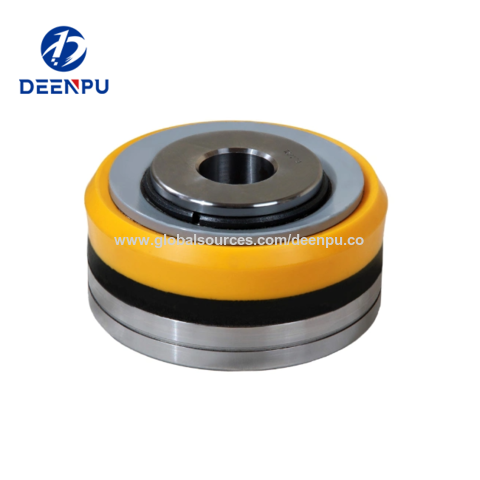
The piston assembly is one of the main parts of the hydraulic end system of the mud pump, and it is also one of the vulnerable parts of the drilling work. The discharge pressure of the mud pump is generated by the reciprocating linear movement of the piston assembly in the piston.
The piston assembly is composed of piston hub, rubber, snap ring, plate, etc. The material of the piston hub is 42CrMo (ASTM4140), and the material of the piston rubber is NBR rubber or Polyurethane Rubber.
Polyurethane rubber has excellent oil resistance and wear resistance. The working temperature is not higher than 120℃, which is suitable for oil-based mud with working pressure below 35Mpa and working environment with high sand content.
Lake Petro has over 10 years of experience in Liners and Pistons, we export a large amount of mud pump parts to many countries and regions in the world. If you are interested in any of our products, please contact sales@lakepetro.com.

Mystique Mud pump Coolant and Lubricant extends mud pump liner and piston life and provides internal lubrication and extra cooling to the coolant system of mud pumps. It extends the life of all liners, even ceramic. Mystique will not cause corrosion or rusting of iron, and is safe with all alloys. Recommened dilution rate of 12.5%. (25 gallons will treat a 200-gallon system.) For use on closed systems.

As usual, winter — or the slow season — is the time most drillers take the time to maintain their equipment in order to get ready for the peak season. One of the main parts that usually needs attention is the mud pump. Sometimes, it is just a set of swabs to bring it up to snuff, but often, tearing it down and inspecting the parts may reveal that other things need attention. For instance, liners. I can usually run three sets of swabs before it is time to change the liner. New liners and swabs last a good long time. The second set of swabs lasts less, and by the time you put in your third set of swabs, it’s time to order new liners. Probably rods too. It’s not always necessary to change pistons when you change swabs. Sometimes just the rubber needs to be changed, saving money. How do you tell? There is a small groove around the outside of the piston. As it wears, the groove will disappear and it’s time for a new piston.
The wear groove on a piston can be a good indicator of the general health of your pump. If the wear is pretty even all around, chances are the pump is in pretty good shape. But if you see wear on one side only, that is a clue to dig deeper. Uneven wear is a sign that the rods are not stroking at the exact angle that they were designed to, which is parallel to the liner. So, it’s time to look at the gear end. Or as some folks call it, “the expensive end.”
The wear groove on a piston can be a good indicator of the general health of your pump. If the wear is pretty even all around, chances are the pump is in pretty good shape. But if you see wear on one side only, that is a clue to dig deeper.
After you get the cover off the gear end, the first thing to look at will be the oil. It needs to be fairly clean, with no drill mud in it. Also look for metal. Some brass is to be expected, but if you put a magnet in the oil and come back later and it has more than a little metal on it, it gets more serious. The brass in the big end of the connecting rod is a wearable part. It is made to be replaced at intervals — usually years. The most common source of metal is from the bull and pinion gears. They transmit the power to the mud. If you look at the pinion gear closely, you will find that it wears faster than the bull gear. This is for two reasons. First, it is at the top of the pump and may not receive adequate lubrication. The second reason is wear. All the teeth on both the bull and pinion gears receive the same amount of wear, but the bull gear has many more teeth to spread the wear. That is why, with a well maintained pump, the bull gear will outlast the pinion gear three, four or even five times. Pinion gears aren’t too expensive and are fairly easy to change.
This process is fairly straightforward machine work, but over the years, I have discovered a trick that will bring a rebuild up to “better than new.” When you tear a pump down, did you ever notice that there is about 1-inch of liner on each end that has no wear? This is because the swab never gets to it. If it has wear closer to one end than the other, your rods are out of adjustment. The trick is to offset grind the journals. I usually offset mine about ¼-inch. This gives me a ½-inch increase in the stroke without weakening the gear end. This turns a 5x6 pump into a 5½x6 pump. More fluid equals better holes. I adjust the rods to the right length to keep from running out the end of the liner, and enjoy the benefits.
Other than age, the problem I have seen with journal wear is improper lubrication. Smaller pumps rely on splash lubrication. This means that as the crank strokes, the rods pick up oil and it lubricates the crank journals. If your gear end is full of drill mud due to bad packing, it’s going to eat your pump. If the oil is clean, but still shows crank wear, you need to look at the oil you are using.
Oil that is too thick will not be very well picked up and won’t find its way into the oil holes in the brass to lubricate the journals. I’ve seen drillers that, when their pump starts knocking, they switch to a heavier weight oil. This actually makes the problem worse. In my experience, factory specified gear end oil is designed for warmer climates. As you move north, it needs to be lighter to do its job. Several drillers I know in the Northern Tier and Canada run 30 weight in their pumps. In Georgia, I run 40W90. Seems to work well.

MUD PUMP Albert A. Ashton. Houston. Tex., assignor to Emseo Derrick & Equipment Company, Los Angeles, Calif., a corporation of California Application October 26, 1942, Serial No. 463,316 i claims. (ci. s- 177) My invention relates to reciprocating pumps, and relates in particular to an improvement in double acting duplex pumps of the type employed in the oil drilling industry for the purpose of pumping drilling mud under high pressure.
It is an object of the invention to provide a pump of this character, which is rigid and amply strong for the service for which it is designed, but is extremely light in weight as compared to many pumps which have been used and are now in use, of no greater capacity.
It is an object of the invention to provide a pump having pistons arranged to be reciprocated through the use of piston rods which are connected to a power source, this pump comprising essentially a front section and a rear section of similar form, these sections being connected together by the application of welds located in a plane or in planes which cross the axes of "the pump cylinders, these welds being disposed between the front and rear sections and joining the same in a rigid lightweight hollow pump structure.
A further object of the invention is to provide in a pump structure of this type front and rear sections adapted to be secured together by use of welds, in a spaced arrangement determined in accordance with the length of the cylinder liner to be employed therein which in turn is controlled by the length of stroke of the pump piston. For example, these front and rear sections may be connected rigidly together in a pump adapted to receive a liner of a length to accommodate a twelve-inch or fourteen-inch stroke, or these sections may be Welded together in positions to receive a longer liner, for example, one which will accommodate an eighteen-inch stroke. In the invention the front and rear sections have pump chambers which provide mouths or openings to. receive the end portions of the liners, there being open spaces betweenthe front and [rear sections across which the liners extend, and in which the liners are exposed. A number of additional advantages result from this arrangement. The amount of metal used in the pump is reduced, and the intermediate portions of the liner are .exposed or have communication with the -exterior of the pump, making it possible for the pump operator to readily observe any leakage Vwhich may occur along the exterior of the pump liner from the pump chambers disposed at the ends of the liner. Being thus observed, the leakage"may be corrected by tightening up on the packing or replacing the same, thereby avoiding the cutting of metal parts as the result of a continued flow of mud under high pressure through the leakage paths.
A further object of the invention is to provide a simple pump section which maybe employed in the manner described herein, this pump section having a U-shaped hollow member comprising a lateially extending hollow inlet body with hollow arms extending upward from the ends of and rear pump sections spaced apart in axial direction, to show the cooperative relation of the front and rear sections.
taken as indicated by the line 3 3" therein, a portion of the view being broken away to show the interior form of the valve pots employed in duplicate in a pump section.
Fig. 4 is a section taken as indicated by the line 4-4 of Fig. 3, to show the manner in which the cylinder liners are disposed and held in the mouths.
In Fig. l I show a power pumping device comprising a power unit I0 and a pump Il of duplex double acting type. This pump II has therein a pair of cylinders or liners I2 in side by side relation. As shown in Fig. 4, each of these liners I2 receives a piston I3 which is reciprocated through a piston rod I4, these piston rods I4 extending through packing means I5 ycarried `by the end wall i6 of the pump II disposed contiguous to the power unit I0, as shown in Fig. -1.
It will be understood that this power unit IIl has Y therein the customary power driven means for reciprocating the piston rods I4, which need not be shown, since the present invention relates to the iiuid end of the device shown in Fig. 1, namely, the pump II.
The pump Ii has a front section I1, and a rear section I8, these sections being in many respects symmetrical, and involving differences as will be hereinafter pointed out. These sections l1 and I 8 are shown in perspective in Fig. 2, in axial relation so that their points of similarity and dii"- ferences may be observed. Each of these sections, as clearly brought out in Figs. 2 and 3, has a hollow U-shaped member I 8 comprising a bottom laterally extending hollow section 2li. reierred to as the hollow inlet member 20, and upwardly extending hollow legs 2I disposed at and connected to the ends of the hollow inlet member 20, these side portions 2| comprising valve pots for the pump sections, the lower ends of which valve pots communicate with the inlet member 20, and the upper ends of these valve pots"ZI having openings 22 of such size that intakes and discharge valves may be passed therethrough into the valve pots 2|, covers 23 being provided for the openings 22.
Each of the sections I1 and I8 includes a pair of juxtaposed pump chambers 24 of cylindric form. These pump chambers are disposed between the valve pots 2| and are positioned above the hollow inlet member 20. The walls of the `chambers 24 merge with the walls of the valve pots .20, and each chamber 24 communicates through an opening 25 with an intermediate portion of the interior space of a valve pot 2 I. Above the pump chambers 24, each section I1|8 has a hollow outlet member 26, shown as a tubular wall, communicating with the upper portions of the valve pots 2 I. Each of the hollow inlet members 20 has a short cylindric wall 21 dening an opening 28, communicating with the interior of kthe hollow inlet member, as best shown in Fig. 4.
the length of stroke of the pistons to be employed in the pump of which the sections I1 and I8 are to become a part. In this procedure of joining the sections I1 and I8, tubular members 30 and 1I may be interposed respectively between the` connections 21 and 29 of the hollow inlet members 20 `and the hollow outlet members 26, and these tubular members 3D and 3| are joined with the connections 21 and 29 by use of annular bodies of welded metal 32 and 88, applied by use of the electric arc or Oxy-acetylene ilame. When these welds are formed, the sections I1 and I 8 are rigidly connected together. The space between the pump chambers 24 of section I1 and the pump chambers 24 of the section I8 depends upon the spatial relation of the sections I1 and I8, which in turn is determined by the lengths of the inserted tubular members 36 and 3|. Each of the pump chambers 24, as best shown in Fig. 4, has an annular liner receiving mouth 34, and the liners I2 are moved through openings 35 in the leftward ends of the pump chambers 24 of the section I1 into positions, as shown in Fig. 4, wherein the end portions of the liners will extend through the mouths 34 of the chambers 24, and the intermediate portions of the liners I2 will extend across the space between the adjacent ends of the pump chambers 24, as also shown in Fig. 1. Covers 36 are provided for the openings 35, -and the liners I2 are held in position and forced rightwardly so as to compress packing rings 31 and 38, Fig. 4, by` hollow frames 39 pressed rightward by screws 40 which pass through the covers `36.
Means are provided for connecting the hollow inlet members 20 with delivery piping through which the mud is carried to the pump. This means comprises a hanged tubular inlet 4| projecting leftward from the hollow inlet member 20 of the front section I1, as shown in Figs. 2 and 4, so that the delivery piping 42 may be conveniently connected thereto as shown in Fig. 1. Also, outlet means are provided for connecting the hollow outlet members 26 with discharge piping, through which the pumped fluid is conveyed to the rotary hose of the well drilling system. This outlet means consists of a flanged outlet fitting 42, formed integrally with and communicating with the central portion of the tubular member 3|. As shown in Fig. 1, an outlet T 43 is ordinarily connected to the outlet fitting 42, this T 43 having a surge chamber 44 connected to the upper connected to the discharge piping 45, the other branch ofthe T being closed by a blind flange 46.
As hereinbefore explained, the capacity of a pump employing the sections I1 and I8, is determined in part by the spacing of the sections I1 and I8 to accommodate liners oi" a selected length. In the pump II, shown in Figs. l and 4, the liners I2 are relatively long, and the pump, accordingly, has relatively high capacity due to the length of the piston stroke. For a shorter liner I2, the lengths of the tubular members 30 and 3| are decreased accordingly so that the sections I8 and I1 will be brought closer together, and for a liner of minimum length, the section 30 may be entirely eliminated and an extremely short section 8| may be employed, under which circumstances the tubular connections 21 of the sections I1 and I8 will be brought substantially into positions of abutment and will be welded directly together by the application of an annular body of welded metal.
Where the pump is to be operated against extremely high pressures, connecting bars 41 and 48 are provided, these bars 41 being formed in cooperative relation on the sections I1 and I8. above and below the chambers 24, and being con nected together by means incorporating bodies of welded metal. Such means, where the sections I1 and I8 are spaced apart, include inserted bars 50 of proper length, the ends of which are joined to the bars 41 and 48 by welds 5|. It will be understood that when the sections I1 and vI4 are connected together in their closest relation, the ends of the bars 41 and 48 will be substantially in abutment and will be welded directly together. Feet 52 are shown on the lower part of the front section I1, on opposite sides of the central vertical plane of the pump II, for connection to the skids 53 of the power pump assem bly shown in Fig. 1.
As shown in Fig. 3, each valve pot 2| has therevin an annular inlet valve seat 55 through which communication of the inlet member 28 with the opening 25 of the associated pump chamber A24 is obtained, and each valve pot 2| has above the opening 25 an outlet valve seat 58. Inlet and outlet valves 51 and 58 are respectively secured in the valve seats 55 and 56.
1. In a double acting duplex pump having pistons adapted to be reciprocated through piston rods connected to a power source, and a pair of removably secured liners to"receive said pistons, the combination of front and rear pump sections, each of said pump sections having a, pair oi juxtaposed pump chambers formed with liner receiving mouths in which opposite end portions of said liners are received, a transverse hollow inlet member below said pump chambers, a trans- `as to form a rigid pump structure comprising annular bodies of welded metal connecting said hollow inlet members together and connecting said hollow outlet members together, said pump l also embracing means to connect the interiors of said inlet members and said outlet members respectively to intake and discharge pipes.
2. In a double acting duplex pump having pistons adapted to be reciprocated through piston rods connected to a power source, and a pair of removably secured liners to receive said pistons, the combination of: front and rear pump sections, each of said pump sections having a pair of juxtaposed pump chambers formed with liner receiving mouths in which opposite end portions o1" said liners are received, a transverse hollow inlet member below said pump chambers, a transverse hollow outlet member above said pump chambers, means forming inlet valve seats connecting said inlet members with said pump chambers, and means forming outlet valve seats connecting said pump chambers with said outlet member; and means connecting said front and rear sections together in cooperative relation so as to form a rigid pump structure comprising tubular fluid conveying members and annular bodies of welded metal connecting said hollow inlet members together and connecting said hollow outlet members together, said"tubular members being arranged between said sections above and below said pump chambers, and the length of said tubular members determining the spacial relation of said sections, and said pump also embracing means to connect the interiors of said inlet members and said outlet members respectively to intake and discharge pipes.
3. In a double acting duplex pump having pistons adapted to be reciprocated through piston rods connected to a power source, and a pair of removably secured liners to receive said pistons, the combination of: iront and rear pump sections. each of said pump sections having a pair oi" juxtaposed pump chambers formed with liner receiving mouths in which opposite end portions of said liners are received, a transverse hollow inlet member below said pump chambers, a transverse hollow outlet` member above said pump chambers, means forming inlet valve seats connecting said inlet members with said pump chambers, and means forming outlet valve seats connecting said pump chambers with said outlet member; and means connecting said front and rear sections together in cooperative relation so as to form a rigid pump structure comprising an nular bodies of welded metal connecting said hollow inlet members together and connecting said hollow outlet members together, said pump also embracing means to connect the interior of said outlet members to a discharge pipe and means to connect the hollow inlet member of said front section to an intake pipe.
4. In a double acting duplex pump having pistons adapted to be reciprocated through piston rods connected to a power source, and a pair of removably secured liners to receive said pistons. the combination of: front and rear pump sections, each of said Dump sections having a pair of juxtaposed pump chambers formed with liner receiving mouths in which opposite end portions of said liners are received, a transverse hollow inlet memberbelow said pump chambers, a transverse hollow outlet member above said pump chambers, means forming inlet valve seats vconnecting said inlet members with said pump chambers, and means yforming outlet valve seats connectingsaid pump chambers with Vsaid outlet member; and means connecting said front and rear sections together in cooperative relation so as to form a rigid pump structure comprising tubular fluid conveying members and annular bodies of welded metal connecting said hollow inlet members together and connecting said-hollow outlet members together, said tubular members Abeing arranged between said sections above and below said pump chambers, the length of said tubular members determining the spacial relation of said sections, said pump also embracingmeans to connect the interior of said, outlet members to adischarge pipe and means to connectthe hollow inlet member of said frontsection to an intake pipe.
5. In a double acting duplex; pump having pistons adapted to be reciprocated through piston rods connected to a power source, and a pair oi removably secured liners to receive said pistons, the combination of: front and rear pump sections, each of said Dump sections having a pair of juxtaposed pump chambers formed with liner receiving mouths in which opposite end portions of said liners are received, a hollow U-shaped body comprising a transverse hollow inlet member positioned below said pump chambers and a pair oi" valve pots extending upward from the ends of said hollow inlet members along the sides of the respective pump chambers, the intermediate portions of said valve pots communicating with said pump chambers, and each ofsaid valve pots having therein an inlet valve seat below and an outlet valve seat above the point of communication of the valve pot with a pump chamber, and a hollow outlet member communicating with the interiors of said valve pots above said outlet valve seats; and means connecting said front and rear sections together in cooperative relation so as to form a rigid pump structure comprising annular bodies of welded metal connecting said hollow in, let members together and connecting said hollow outlet members together, said pump also embracing means to connect the interiors of said inlet members and said outlet members respectively to intake and discharge pipes.
6. In a double acting duplex pump having pistons adapted to be-reciprocated through piston rods connected to a power source, and a pair of removably secured liners to receive said pistons. the combination of: front and rear pump sections. each of said pump sections having a pair of juxtaposed pump chambers iormed with liner receiving mouths in which opposite end portions of said liners are received, a hollow U-shaped body comprising a transverse hollow inlet member positioned below said pump chambers and a pair of valve pots extending upward from the ends of said hollow inlet members along the sides of the respective pump chambers, the intermediate portions of said valve pots communicating with said pump chambers, and each of said valve pots having therein an inlet valve seat below and an outlet valve seat above the point of communication of the valve pot with a pump chamber, and a hollow outlet member communicating with the interiors of said valve pots above said outlet valve seats; and means connecting said front and rear sections together in cooperative relation so as to form a rigid pump structure comprising t ular iluid conveying members and annular bod es of welded metal connecting said hollow inlet members together and connecting said hollow outlet members together, said tubular member being arranged between said sections above and bliw said pump chambers, the length of said tub ar members determining the spacial relation of said sections, said pump also embracing means to connect lthe interior of said outlet members to a discharge pipe and means to connect ther hollow inlet member of said front section to an intake pipe.
"7. In a double acting duplex pump having pistons adapted to be reciprocated through piston rods connected to a power source, and a pair of removably secured liners to receive said pistons, the combination of: front and rear pump sections, each of said pump sections having a pair of juxtaposed pump chambers formed with liner receiving mouths in which opposite end portions of said liners are received; a hollow U-shaped body comprising a transverse hollow inlet member positioned below said pump chambers and a pair of valve pots extending upward from the ends of said hollow inlet members along the sides of the l respective pump chambers, the intermediate portions o! said"valve pots communicating with said pump chambers, and each of said valve pots having therein an inlet valve seat below and an outlet valve seat above the point of communication of the valve pot with a pump chamber, and a hollow outlet member communicating with the interiors of said valve pots above said outlet valve seats; means connecting said front and rear sections together in cooperative relation so as to form a rigid pump Structure comprising annular bodies of welded metal connecting said hollow inlet members together and connecting said hollow outlet members together, said pump also embracing
Kverneland, Hege, Kyllingstad, Åge, and Magne Moe. "Development and Performance Testing of the Hex Mud Pump." Paper presented at the SPE/IADC Drilling Conference, Amsterdam, Netherlands, February 2003. doi: https://doi.org/10.2118/79831-MS
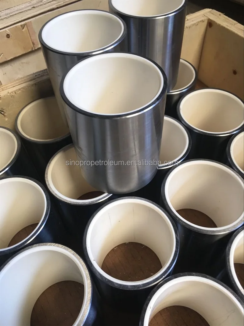
Table 114. Dezhou L&A Petroleum Machinery Co., Ltd Mud Pump Liner Sales (K Units), Revenue (US$ Million), Price (US$/Unit) and Gross Margin (2017-2022)
Table 134. Dongying Lake Petroleum Technology CO., Ltd Mud Pump Liner Sales (K Units), Revenue (US$ Million), Price (US$/Unit) and Gross Margin (2017-2022)


 8613371530291